US10522093B2 - Driving circuit and display panel - Google Patents
Driving circuit and display panel Download PDFInfo
- Publication number
- US10522093B2 US10522093B2 US15/910,026 US201815910026A US10522093B2 US 10522093 B2 US10522093 B2 US 10522093B2 US 201815910026 A US201815910026 A US 201815910026A US 10522093 B2 US10522093 B2 US 10522093B2
- Authority
- US
- United States
- Prior art keywords
- signal line
- buffer layer
- edge
- conductive wires
- long side
- Prior art date
- Legal status (The legal status is an assumption and is not a legal conclusion. Google has not performed a legal analysis and makes no representation as to the accuracy of the status listed.)
- Active, expires
Links
- 239000010409 thin film Substances 0.000 claims description 86
- 229910052751 metal Inorganic materials 0.000 claims description 4
- 239000002184 metal Substances 0.000 claims description 4
- 229910052710 silicon Inorganic materials 0.000 claims description 3
- 239000010703 silicon Substances 0.000 claims description 3
- 239000011810 insulating material Substances 0.000 claims 2
- 239000010410 layer Substances 0.000 description 162
- 238000009413 insulation Methods 0.000 description 31
- 239000000758 substrate Substances 0.000 description 13
- 238000010586 diagram Methods 0.000 description 12
- 230000007704 transition Effects 0.000 description 9
- 230000007257 malfunction Effects 0.000 description 8
- 238000000034 method Methods 0.000 description 8
- 238000005530 etching Methods 0.000 description 7
- 239000000463 material Substances 0.000 description 7
- 238000004519 manufacturing process Methods 0.000 description 6
- 230000007547 defect Effects 0.000 description 5
- 229910021417 amorphous silicon Inorganic materials 0.000 description 4
- 239000010408 film Substances 0.000 description 4
- 239000011241 protective layer Substances 0.000 description 4
- 239000004065 semiconductor Substances 0.000 description 3
- 230000008901 benefit Effects 0.000 description 2
- 230000000052 comparative effect Effects 0.000 description 2
- 238000012986 modification Methods 0.000 description 2
- 230000004048 modification Effects 0.000 description 2
- RYGMFSIKBFXOCR-UHFFFAOYSA-N Copper Chemical compound [Cu] RYGMFSIKBFXOCR-UHFFFAOYSA-N 0.000 description 1
- ZOKXTWBITQBERF-UHFFFAOYSA-N Molybdenum Chemical compound [Mo] ZOKXTWBITQBERF-UHFFFAOYSA-N 0.000 description 1
- XUIMIQQOPSSXEZ-UHFFFAOYSA-N Silicon Chemical compound [Si] XUIMIQQOPSSXEZ-UHFFFAOYSA-N 0.000 description 1
- -1 amorphous silicon Chemical compound 0.000 description 1
- 229910052802 copper Inorganic materials 0.000 description 1
- 239000010949 copper Substances 0.000 description 1
- BIXHRBFZLLFBFL-UHFFFAOYSA-N germanium nitride Chemical compound N#[Ge]N([Ge]#N)[Ge]#N BIXHRBFZLLFBFL-UHFFFAOYSA-N 0.000 description 1
- 239000012774 insulation material Substances 0.000 description 1
- 239000004973 liquid crystal related substance Substances 0.000 description 1
- 229910052750 molybdenum Inorganic materials 0.000 description 1
- 239000011733 molybdenum Substances 0.000 description 1
- 229910021421 monocrystalline silicon Inorganic materials 0.000 description 1
- 238000001020 plasma etching Methods 0.000 description 1
- 229910021420 polycrystalline silicon Inorganic materials 0.000 description 1
- 229920005591 polysilicon Polymers 0.000 description 1
Images


Classifications
-
- G—PHYSICS
- G09—EDUCATION; CRYPTOGRAPHY; DISPLAY; ADVERTISING; SEALS
- G09G—ARRANGEMENTS OR CIRCUITS FOR CONTROL OF INDICATING DEVICES USING STATIC MEANS TO PRESENT VARIABLE INFORMATION
- G09G3/00—Control arrangements or circuits, of interest only in connection with visual indicators other than cathode-ray tubes
- G09G3/20—Control arrangements or circuits, of interest only in connection with visual indicators other than cathode-ray tubes for presentation of an assembly of a number of characters, e.g. a page, by composing the assembly by combination of individual elements arranged in a matrix no fixed position being assigned to or needed to be assigned to the individual characters or partial characters
- G09G3/34—Control arrangements or circuits, of interest only in connection with visual indicators other than cathode-ray tubes for presentation of an assembly of a number of characters, e.g. a page, by composing the assembly by combination of individual elements arranged in a matrix no fixed position being assigned to or needed to be assigned to the individual characters or partial characters by control of light from an independent source
- G09G3/36—Control arrangements or circuits, of interest only in connection with visual indicators other than cathode-ray tubes for presentation of an assembly of a number of characters, e.g. a page, by composing the assembly by combination of individual elements arranged in a matrix no fixed position being assigned to or needed to be assigned to the individual characters or partial characters by control of light from an independent source using liquid crystals
- G09G3/3611—Control of matrices with row and column drivers
- G09G3/3674—Details of drivers for scan electrodes
-
- G—PHYSICS
- G09—EDUCATION; CRYPTOGRAPHY; DISPLAY; ADVERTISING; SEALS
- G09G—ARRANGEMENTS OR CIRCUITS FOR CONTROL OF INDICATING DEVICES USING STATIC MEANS TO PRESENT VARIABLE INFORMATION
- G09G3/00—Control arrangements or circuits, of interest only in connection with visual indicators other than cathode-ray tubes
- G09G3/20—Control arrangements or circuits, of interest only in connection with visual indicators other than cathode-ray tubes for presentation of an assembly of a number of characters, e.g. a page, by composing the assembly by combination of individual elements arranged in a matrix no fixed position being assigned to or needed to be assigned to the individual characters or partial characters
- G09G3/34—Control arrangements or circuits, of interest only in connection with visual indicators other than cathode-ray tubes for presentation of an assembly of a number of characters, e.g. a page, by composing the assembly by combination of individual elements arranged in a matrix no fixed position being assigned to or needed to be assigned to the individual characters or partial characters by control of light from an independent source
- G09G3/3406—Control of illumination source
-
- G—PHYSICS
- G02—OPTICS
- G02F—OPTICAL DEVICES OR ARRANGEMENTS FOR THE CONTROL OF LIGHT BY MODIFICATION OF THE OPTICAL PROPERTIES OF THE MEDIA OF THE ELEMENTS INVOLVED THEREIN; NON-LINEAR OPTICS; FREQUENCY-CHANGING OF LIGHT; OPTICAL LOGIC ELEMENTS; OPTICAL ANALOGUE/DIGITAL CONVERTERS
- G02F1/00—Devices or arrangements for the control of the intensity, colour, phase, polarisation or direction of light arriving from an independent light source, e.g. switching, gating or modulating; Non-linear optics
- G02F1/01—Devices or arrangements for the control of the intensity, colour, phase, polarisation or direction of light arriving from an independent light source, e.g. switching, gating or modulating; Non-linear optics for the control of the intensity, phase, polarisation or colour
- G02F1/13—Devices or arrangements for the control of the intensity, colour, phase, polarisation or direction of light arriving from an independent light source, e.g. switching, gating or modulating; Non-linear optics for the control of the intensity, phase, polarisation or colour based on liquid crystals, e.g. single liquid crystal display cells
- G02F1/133—Constructional arrangements; Operation of liquid crystal cells; Circuit arrangements
- G02F1/13306—Circuit arrangements or driving methods for the control of single liquid crystal cells
-
- G—PHYSICS
- G02—OPTICS
- G02F—OPTICAL DEVICES OR ARRANGEMENTS FOR THE CONTROL OF LIGHT BY MODIFICATION OF THE OPTICAL PROPERTIES OF THE MEDIA OF THE ELEMENTS INVOLVED THEREIN; NON-LINEAR OPTICS; FREQUENCY-CHANGING OF LIGHT; OPTICAL LOGIC ELEMENTS; OPTICAL ANALOGUE/DIGITAL CONVERTERS
- G02F1/00—Devices or arrangements for the control of the intensity, colour, phase, polarisation or direction of light arriving from an independent light source, e.g. switching, gating or modulating; Non-linear optics
- G02F1/01—Devices or arrangements for the control of the intensity, colour, phase, polarisation or direction of light arriving from an independent light source, e.g. switching, gating or modulating; Non-linear optics for the control of the intensity, phase, polarisation or colour
- G02F1/13—Devices or arrangements for the control of the intensity, colour, phase, polarisation or direction of light arriving from an independent light source, e.g. switching, gating or modulating; Non-linear optics for the control of the intensity, phase, polarisation or colour based on liquid crystals, e.g. single liquid crystal display cells
- G02F1/133—Constructional arrangements; Operation of liquid crystal cells; Circuit arrangements
- G02F1/136—Liquid crystal cells structurally associated with a semi-conducting layer or substrate, e.g. cells forming part of an integrated circuit
- G02F1/1362—Active matrix addressed cells
- G02F1/136286—Wiring, e.g. gate line, drain line
-
- G—PHYSICS
- G11—INFORMATION STORAGE
- G11C—STATIC STORES
- G11C19/00—Digital stores in which the information is moved stepwise, e.g. shift registers
- G11C19/28—Digital stores in which the information is moved stepwise, e.g. shift registers using semiconductor elements
-
- G—PHYSICS
- G09—EDUCATION; CRYPTOGRAPHY; DISPLAY; ADVERTISING; SEALS
- G09G—ARRANGEMENTS OR CIRCUITS FOR CONTROL OF INDICATING DEVICES USING STATIC MEANS TO PRESENT VARIABLE INFORMATION
- G09G2310/00—Command of the display device
- G09G2310/02—Addressing, scanning or driving the display screen or processing steps related thereto
- G09G2310/0264—Details of driving circuits
- G09G2310/0286—Details of a shift registers arranged for use in a driving circuit
Definitions
- the invention relates to a driving circuit and a display panel and more particularly relates to a driving circuit having a buffer layer and a display panel.
- Existing gate-driver-on-array (GOA) display panels are mostly comprised of thin film transistors (TFT).
- TFT thin film transistors
- a portion of the signal line located at the first layer and a portion of the signal line located at the second layer are interlaced.
- defects are more likely to occur on the corners of the signal line located at the second layer.
- the stress is concentrated on the protective layer around the defects, which further creates defects on the film layers of the protective layer.
- etching solutions later applied in the process may etch an insulation layer located between the signal lines in the two layers through the defects. As such, leakage of current and short circuits occur between the signal lines in the two layers, which leads to the output malfunction of the driving circuits. Therefore, methods for solving such a problem is needed.
- the invention provides a driving circuit capable of correcting signal malfunction caused by current leakage of conductive wires and signal lines.
- the invention provides a display panel capable of correcting signal malfunction caused by current leakage of conductive wires and signal lines.
- a driving circuit including an output circuit, a pull-down module, a plurality of conductive wires, at least one first signal line, and a buffer layer.
- the conductive wires are electrically connected between the output circuit and the pull-down module.
- the at least one first signal line is configured to couple the output circuit and the pull-down module to a driving control signal, wherein a first overlapping region exists between the at least one first signal line and a portion of the conductive wires.
- the buffer layer is disposed between the at least one first signal line and a portion of the conductive wires.
- the buffer layer includes an overlapping portion and an extending portion. The overlapping portion is at least located in the first overlapping region, and the extending portion is located outside of the overlapping portion. A thickness of the overlapping portion is greater than a thickness of the extending portion.
- a display panel including a pixel region and a driving circuit region located on at least one side of the pixel region.
- the display panel includes a pixel array and a gate driving circuit.
- the pixel array is located in the pixel region.
- the pixel array includes a plurality of data lines, a plurality of scan lines, and a plurality of pixel structures electrically connected to the scan lines and the data lines.
- the gate driving circuit is located in the driving circuit region and electrically connected to the pixel array.
- the gate driving circuit includes an output circuit, a pull-down module, a plurality of conductive wires, at least one first signal line, and a buffer layer. An end of the output circuit is connected to the pixel array.
- the conductive wires are connected between the output circuit and the pull-down module.
- the at least one first signal line is configured to couple the output circuit and the pull-down module to a driving control signal.
- a first overlapping region exists between the at least one first signal line and a portion of the conductive wires.
- the buffer layer is disposed between the at least one first signal line and a portion of the conductive wires.
- the buffer layer includes an overlapping portion and an extending portion. The overlapping portion is at least located in the first overlapping region, and the extending portion is located outside of the overlapping portion. A thickness of the overlapping portion is greater than a thickness of the extending portion.
- the at least one first signal line is coupled to the driving control signal
- the buffer layer is disposed between the at least one first signal line and the conductive wires.
- the design of the buffer layer is able to disperse the stress, so as to avoid current leakage between the at least one first signal line and the conductive wires in the driving circuit.
- FIG. 1 is a schematic diagram of a driving circuit in an embodiment of the invention.
- FIG. 2 is a schematic equivalent circuit diagram of a driving circuit in an embodiment of the invention.
- FIG. 3A is a schematic diagram of a portion of circuit layout of a driving circuit in an embodiment of the invention.
- FIG. 3B is a schematic cross-sectional view along a sectional line AA′ in FIG. 3A .
- FIG. 4 is a schematic diagram of a portion of circuit layout of a driving circuit in an embodiment of the invention.
- FIG. 5 is schematic diagram of a portion of circuit layout of a driving circuit in an embodiment of the invention.
- FIG. 6 is a schematic diagram of a portion of circuit layout of a driving circuit in an embodiment of the invention.
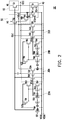
- FIG. 7 is a schematic cross-sectional view of a portion of circuit layout of a driving circuit in a comparative example of the invention.
- FIG. 8 is a schematic cross-sectional view of a portion of circuit layout of a driving circuit in an embodiment of the invention.
- FIG. 9 is a schematic cross-sectional view of a portion of circuit layout of a driving circuit in an embodiment of the invention.
- FIG. 10 is a schematic cross-sectional view of a portion of circuit layout of a driving circuit in an embodiment of the invention.
- FIG. 11A is a schematic cross-sectional view of a portion of circuit layout of a driving circuit in an embodiment of the invention.
- FIG. 11B is a schematic cross-sectional view of a portion of circuit layout of a driving circuit in an embodiment of the invention.
- FIG. 12 is a schematic top view of a display panel in an embodiment of the invention.
- a driving circuit applied in a display panel is taken as an example in the following embodiments. Nevertheless, the driving circuit provided in the invention is not limited to being applied in display panels but may be applied as a driving circuit of other electronic devices.
- a display panel 1000 includes a pixel region 1100 and a driving circuit region 1200 located on at least one side of the pixel region 1100 , as shown in FIG. 12 .
- the driving circuit region 1200 is usually located on a substrate BS in an exemplary liquid crystal display (LCD) panel. More specifically, a display panel includes a pixel array PA and a driving circuit.
- the driving circuit includes a gate driving circuit GD and a source driving circuit DD.
- the pixel array PA is located in the pixel region 1100 , while the driving circuit is located in the driving circuit region 1200 .
- the pixel array PA includes a plurality of scan lines SL 1 -SLn, a plurality of data lines DL 1 -DLm, and a plurality of pixel structures P electrically connected to the scan lines SL 1 -SLn and the data lines DL 1 -DLm.
- the gate driving circuit GD and the source driving circuit DD are located in the driving circuit region 1200 and are electrically connected to the pixel array PA.
- the aforementioned pixel structures P may be pixel structures of any known display panels.
- the gate driving circuit GD is taken as an example in the following embodiment of the invention, whereas the source driving circuit DD may also be applicable in the invention.
- FIG. 1 is a schematic diagram of a driving circuit in an embodiment of the invention
- FIG. 2 is a schematic equivalent circuit diagram of a driving circuit in an embodiment of the invention.
- a driving circuit DC includes an output circuit 10 and a pull-down module PM coupled to the output circuit 10 .
- the output circuit 10 and the pull-down module PM are coupled to a driving control signal Q(n) through a first signal line.
- the first signal line is configured to, for example, transmit the driving control signal Q(n).
- a second signal line is configured to transmit a clock signal HC to the output circuit 10 .
- the pull-down module PM includes a voltage-stabilizing control circuit 20 , a voltage-stabilizing circuit 30 , and a pull-down circuit 40 .
- the output circuit 10 is, for example, electrically connected to the voltage-stabilizing circuit 30 and the pull-down circuit 40 though conductive wires.
- the output circuit 10 is electrically connected to a pixel array PA though an output signal line.
- the pixel array PA is located in the pixel region 1100 , as shown in FIG. 12 .
- the output circuit 10 transmits a driving signal G(n) to the output signal line based on the driving control signal Q(n).
- the output circuit 10 is electrically connected to the pixel array PA in the pixel region 1100 through the output signal line.
- the driving circuit DC further includes a downstream circuit 50 .
- the downstream circuit 50 is coupled to the driving control signal Q(n) through the at least one first signal line and is electrically connected to the output circuit 10 .
- the driving circuit DC is, for example, a gate driving circuit. That is to say, the gate driving circuit GD includes an output circuit 10 , a pull-down module PM, a plurality of conductive wires, and at least one first signal line.
- the output circuit 10 of the gate driving circuit GD transmits the driving signal G(n) to the output signal line based on the driving control signal Q(n).
- the output circuit 10 is electrically connected to the scan line SLn in the pixel array PA through the output signal line.
- FIG. 2 is a schematic equivalent circuit diagram in an embodiment of FIG. 1 ; however, the invention is not limited thereto.
- the output circuit 10 of the driving circuit DC includes a thin film transistor T 21 .
- the thin film transistor T 21 includes a gate, a source, and a drain.
- a first end (e.g., the gate) of the thin film transistor T 21 is connected to the at least one first signal line and receives the driving control signal Q(n).
- the driving control signal Q(n) is, for example, a high-voltage signal.
- a second end (e.g., the source) of the thin film transistor T 21 is connected to the second signal line and receives the clock signal HC.
- a third end (e.g., the drain) of the thin film transistor T 21 is connected to the output signal line and outputs the driving signal G(n).
- the downstream circuit 50 of the driving circuit DC is, for example, electrically connected to the output circuit 10 , the voltage-stabilizing control circuit 20 , the voltage-stabilizing circuit 30 , and the pull-down circuit 40 through the at least one first signal line and/or the conductive wires.
- the second signal line transmits the clock signal HC to the downstream circuit 50 .
- the downstream circuit 50 of the driving circuit DC includes a thin film transistor T 11 and a thin film transistor T 12 .
- a first end of the thin film transistor T 11 is electrically connected to the thin film transistor T 12 through the conductive wires.
- a second end of the thin film transistor T 11 is electrically connected to a voltage VGH.
- a third end of the thin film transistor T 11 is electrically connected to a first signal line configured to transmit a control signal Q(n+4).
- a first end of the thin film transistor T 12 is electrically connected to a first signal line configured to transmit the driving control signal Q(n).
- a second end of the thin film transistor T 12 is electrically connected to a second signal line configured to transmit the clock signal HC.
- a third end of the thin film transistor T 12 is electrically connected to a start signal ST(n) and the first end of the thin film transistor T 11 .
- the voltage-stabilizing control circuit 20 of the driving circuit DC is, for example, electrically connected to the voltage-stabilizing circuit 30 through the conductive wires.
- a third signal line transmits a clock signal LC to the voltage-stabilizing control circuit 20 .
- the voltage-stabilizing control circuit 20 , the voltage-stabilizing circuit 30 , and the pull-down circuit 40 are electrically connected to a stationary voltage VSS through the conductive wires.
- the driving circuit DC includes a voltage-stabilizing control circuit 20 A, a voltage-stabilizing control circuit 20 B, a voltage-stabilizing circuit 30 A, a voltage-stabilizing circuit 30 B, and a pull-down circuit 40 .
- the voltage-stabilizing control circuit 20 A includes thin film transistors T 51 to T 56 .
- a first end of the thin film transistor T 51 , a second end of the thin film transistor T 51 , and a second end of the thin film transistor T 53 are electrically connected to a third signal line that transmits a clock signal LC 1 .
- a third end of the thin film transistor T 51 is electrically connected to a second end of the thin film transistor T 52 , a first end of the thin film transistor T 53 , and a second end of the thin film transistor T 55 through the conductive wires.
- a first end of the thin film transistor T 52 and a first end of the thin film transistor T 54 are electrically connected to the first signal line configured to transmit the driving control signal Q(n).
- a first end of the thin film transistor T 55 and a first end of the thin film transistor T 56 are electrically connected to the first signal line configured to transmit a control signal Q(n ⁇ 2).
- a third end of the thin film transistor T 53 , a second end of the thin film transistor T 54 , and a second end of the thin film transistor T 56 are electrically connected to a signal P(n) and the voltage-stabilizing circuit 30 A through the conductive wires.
- Third ends of the thin film transistors T 52 , T 54 , T 55 , and T 56 are electrically connected to a stationary voltage VSSQ through the conductive wires.
- the voltage-stabilizing circuit 30 A includes a thin film transistor T 42 , a thin film transistor T 32 , and a thin film transistor T 34 .
- First ends of the thin film transistors T 42 , T 32 , and T 34 are electrically connected to the signal P(n) and the voltage-stabilizing control circuit 20 A through the conductive wires.
- a second end of the thin film transistor T 42 is electrically connected to the first signal line configured to transmit the driving control signal Q(n).
- a second end of the thin film transistor T 32 is electrically connected to the voltage-stabilizing circuit 30 B and the output signal line.
- a second end of the thin film transistor T 34 is electrically connected to the voltage-stabilizing circuit 30 B and the downstream circuit 50 through the conductive wires.
- Third ends of the thin film transistors T 42 and T 34 are electrically connected to the stationary voltage VSSQ through the conductive wires.
- a third end of the thin film transistor T 32 is electrically connected to a stationary voltage VSSG through the conductive wires.
- the voltage-stabilizing control circuit 20 B includes thin film transistors T 61 to T 66 .
- a first end of the thin film transistor T 61 , a second end of the thin film transistor T 61 , and a second end of the thin film transistor T 63 are electrically connected to a third signal line that transmits a clock signal LC 2 .
- a third end of the thin film transistor T 61 is electrically connected to a second of the thin film transistor T 62 , a first end of the thin film transistor T 63 , and a second end of the thin film transistor T 65 through the conductive wires.
- a first end of the thin film transistor T 62 and a first end of the thin film transistor T 64 are electrically connected to a first signal line configured to transmit the driving control signal Q(n).
- a first end of the thin film transistor T 65 and a first end of the thin film transistor T 66 are electrically connected to the first signal line configured to transmit the control signal Q(n ⁇ 2).
- a third end of the thin film transistor T 63 , a second end of the thin film transistor T 64 , and a second end of the thin film transistor T 66 are electrically connected to a signal K(n) and the voltage-stabilizing circuit 30 B through the conductive wires.
- Third ends of the thin film transistors T 62 , T 64 , T 65 , and T 66 are electrically connected to the stationary voltage VSSQ through the conductive wires.
- the clock signal LC 2 transmitted to the voltage-stabilizing control circuit 20 B and the clock signal LC 1 transmitted to the voltage-stabilizing control circuit 20 A are reverse signals.
- the voltage-stabilizing circuit 30 B includes a thin film transistor T 43 , a thin film transistor T 33 , and a thin film transistor T 35 .
- First ends of the thin film transistors T 43 , T 33 , and T 35 are electrically connected to the signal K(n) and the voltage-stabilizing control circuit 20 B through the conductive wires.
- a second end of the thin film transistor T 43 is electrically connected to a first signal line configured to transmit the driving control signal Q(n).
- a second end of the thin film transistor T 33 is electrically connected to the voltage-stabilizing circuit 30 A and the output signal line.
- a second end of the thin film transistor T 35 is electrically connected to the voltage-stabilizing circuit 30 A and the downstream circuit 50 through the conductive wires.
- Third ends of the thin film transistors T 43 and T 35 are electrically connected to the stationary voltage VSSQ through the conductive wires.
- a third end of the thin film transistor T 33 is electrically connected to the stationary voltage VSSG through the conductive wires.
- the pull-down circuit 40 includes a thin film transistor T 31 and a thin film transistor T 41 .
- a first end of the thin film transistor T 31 is, for example, electrically connected to the next-four-stage driving signal G(n+4).
- a second end of the thin film transistor T 31 is electrically connected to the output circuit 10 and the driving signal G(n) through the conductive wires.
- a third end of the thin film transistor T 31 is electrically connected to the stationary voltage VSSG through the conductive wires.
- a first end of the thin film transistor T 41 is electrically connected to a signal ST(n+4).
- a second end of the thin film transistor T 41 is electrically connected to the output circuit 10 and the downstream circuit 50 through the conductive wires.
- a third end of the thin film transistor T 41 is electrically connected to the stationary voltage VSSQ through the conductive wires.
- the driving circuit DC further includes a thin film transistor T 44 .
- a first end of the thin film transistor T 44 is electrically connected to a signal ST.
- a second end of the thin film transistor T 44 is electrically connected to the first signal line configured to transmit the driving control signal Q(n).
- a third end of the thin film transistor T 44 is electrically connected to the stationary voltage VSSQ through the conductive wires.
- FIG. 3A schematically depicts a portion of a circuit layout of a driving circuit in an embodiment of the invention (for instance, a portion of a circuit layout of the driving circuit in FIG. 2 ).
- FIG. 3B is a schematic cross-sectional view along a sectional line AA′ in FIG. 3A .
- conductive wires L 1 to L 4 are located on a substrate BS.
- An output signal line GL, a first signal line QL, a second signal line C 1 , and a third signal line are located on the conductive wires L 1 to L 4 .
- An insulation layer 110 is interposed between the conductive wires L 1 to L 4 and the output signal line GL, the first signal line QL, the second signal line C 1 , and the third signal line.
- the conductive wires L 1 to L 4 and the output signal line GL, the first signal line QL, the second signal line C 1 , and the third signal line (not depicted) belong to different metal layers.
- the first signal line QL includes a top layer Q 1 and a bottom layer Q 2 located between the top layer Q 1 and the insulation layer 110 .
- a material of the top layer Q 1 of the first signal line QL includes copper, for instance, while a material of the bottom layer Q 2 of the first signal line QL includes molybdenum, for instance.
- a thickness of the top layer Q 1 of the first signal line QL is greater than a thickness of the bottom layer Q 2 of the first signal layer QL.
- a side of the top layer Q 1 of the first signal line QL may be aligned to a side of the bottom layer Q 2 of the first signal layer QL. Nevertheless, the invention is not limited to the above. In other embodiments, the side of the bottom layer Q 2 of the first signal line QL may shrink within the side of the top layer Q 1 of the first signal line QL.
- a width of the bottom layer Q 2 of the first signal line QL on an orthogonal projection surface is smaller than a width of the top layer Q 1 of the first signal line QL on an orthogonal projection surface.
- the output signal line GL, the first signal line QL, the second signal line C 1 , and the third signal line may be made of the same material and composed of the same stacked layers.
- the first signal line QL is, for example, configured to transmit a driving control signal (such as a driving control signal Q(n)).
- the second signal line C 1 is, for example, configured to transmit a clock signal (such as a clock signal HC).
- the output signal GL is, for example, configured to transmit a driving signal (such as a driving signal G(n)).
- the output signal line GL is, for example, a gate signal line, and the output signal line is electrically connected to a scan line SLn in a pixel array PA.
- the invention is not limited thereto.
- three signal lines may be interlaced with one conductive wire.
- one signal line may be interlaced with more than one conductive wire.
- the three signal lines are depicted to be located on the four conductive wires in FIG. 3A , the invention is not limited thereto.
- a signal line may be located under four conductive wires, and an insulation layer may be interposed between the signal line and the four conductive wires.
- Another two conductive wires may be located on the four conductive wires, and another insulation layer is interposed between the two conductive wires and the four conductive wires.
- An overlapping region R 1 exists between the first signal line QL and the conductive wires L 1 to L 4 . More specifically, the first signal line QL and the conductive wires L 1 to L 4 are interlaced to form the overlapping region R 1 .
- a first part BF 1 of a buffer layer BF is located between the first signal line QL and the conductive wires L 1 to L 4 . In an embodiment, the first part BF 1 of the buffer layer BF is located between the first signal line QL and the insulation layer 110 .
- the first part BF 1 of the buffer layer BF includes an overlapping portion OR and an extending portion ER.
- the overlapping region OR is at least located in the overlapping region R 1 , and the extending portion ER is located outside of the overlapping portion OR.
- the extending portion ER is located on two sides of the overlapping portion OR. Nevertheless, the invention is not limited to the above. In other embodiments, the extending portion ER is located around the overlapping portion OR. A thickness of the overlapping portion OR is greater than a thickness of the extending portion ER.
- the overlapping portion OR of the first part BF 1 of the buffer layer BF exceeds the overlapping region R 1 of the first signal line QL and the conductive lines L 1 to L 4 on an orthogonal projection surface.
- a material of the buffer layer BF includes, for example, silicon (such as amorphous silicon, polysilicon, monocrystalline silicon, and doped amorphous silicon stacked layers), an insulation material (such as germanium nitride (GeNx)), or other appropriate materials.
- the overlapping portion OR has, for example, a double-layered structure.
- the overlapping portion OR includes a doped portion OR 1 and an amorphous portion OR 2 .
- a material of the doped portion OR 1 includes doped amorphous silicon (such as N-type doping).
- Materials of the extending portion ER and the amorphous portion OR 2 include undoped amorphous silicon.
- the first part BF 1 of the buffer layer BF includes the overlapping portion OR and the extending portion ER, the invention is not limited thereto. In some embodiments, other parts of the buffer layer BF also include the overlapping portion OR and the extending portion ER.
- the first signal line QL has a first long side LS 1 and a second long side LS 2 .
- the first part BF 1 of the buffer layer BF has a first edge SW 1 and a second edge SW 2 .
- the first edge SW 1 extends along an extending direction of the first long side LS 1 .
- a first distance D 1 is between the first edge SW 1 and the first long side LS 1 on an orthogonal projection surface.
- the orthogonal projection surface here refers to an orthogonal projection on an upper surface of the substrate BS.
- the second edge SW 2 extends along an extending direction of the second long side LS 2 .
- a second distance D 2 is between the second edge SW 2 and the second long side LS 2 on an orthogonal projection surface.
- D 1 D 2 .
- the first edge SW 1 is parallel to the first long side LS 1
- the second edge SW 2 is parallel to the second long side LS 2 .
- a width of an orthogonal projection of the first signal line QL on a surface of the substrate BS is A 1
- a width of an orthogonal projection of the overlapping portion OR on a surface of the substrate BS is A 2 .
- a ratio of A 1 /A 2 falls, for example, in a range from 0.05 to 1.
- a 1 /A 2 falls, for example, in a range from 0.7 to 0.9.
- the overlapping portion OR has a first border OS 1 and a second border OS 2 .
- the first border OS 1 falls between the first edge SW 1 and the first long side LS 1 on an orthogonal projection surface.
- the second border OS 2 falls between the second edge SW 2 and the second long side LS 2 on an orthogonal projection surface.
- the first border OS 1 extends along an extending direction of the first edge SW 1 on an orthogonal projection surface and is, for example, parallel to the first edge SW 1 .
- the second border OS 2 extends along an extending direction of the second edge SW 2 on an orthogonal projection surface and is, for example, parallel to the second edge SW 2 .
- the overlapping portion OR has a width W 1 that exceeds the first long side LS 1 of the first signal line QL on an orthogonal projection surface. That is to say, the width W 1 is a distance between the first border OS 1 and the first long side LS 1 on the orthogonal projection surface.
- the extending portion ER has a second width W 2 that exceeds the first long side LS 2 of the first signal line QL. That is to say, the width W 2 is a distance between the first edge SW 1 and the first long side LS 1 on the orthogonal projection surface.
- W 1 /W 2 falls, for example, in a range from 0.01 to 0.99.
- W 1 /W 2 falls, for example, in a range from 0.05 to 0.5.
- a width of the overlapping portion OR exceeding the first long side LS 1 of the first signal line QL on the orthogonal projection surface equals a width of the overlapping portion OR exceeding the second long side LS 2 of the first signal line QL on the orthogonal projection surface.
- a width of the extending portion ER exceeding the first long side LS 1 of the first signal line QL on the orthogonal projection surface equals a width of the extending portion ER exceeding the second long side LS 2 of the first signal line QL on the orthogonal projection surface.
- An overlapping region R 2 exists between the second signal line C 1 and the conductive wires L 1 to L 4 . More specifically, the second signal line C 1 and the conductive lines L 1 to L 4 are interlaced with each other to form the overlapping region R 2 .
- a second part BF 2 of the buffer layer BF is further disposed between the second signal line C 1 and the conductive wires L 1 to L 4 and is at least located in the overlapping region R 2 .
- an overlapping portion OR of the second part BF 2 of the buffer layer BF exceeds the overlapping region R 2 of the second signal line C 1 and the conductive wires L 1 to L 4 on an orthogonal projection surface.
- the second signal line C 1 has a first long side LS 3 and a second long side LS 4 .
- the second part BF 2 of the buffer layer BF has a first edge SW 3 and the second edge SW 4 .
- the first edge SW 3 extends along an extending direction of the first long side LS 3 .
- a first distance D 3 is between the first edge SW 3 and the first long side LS 3 on an orthogonal projection surface.
- the orthogonal projection surface is, for example, a surface of the substrate BS facing the second signal line C 1 .
- the second edge SW 4 extends along an extending direction of the second long side LS 4 .
- a second distance D 4 is between the second edge SW 4 and the second long side LS 4 on an orthogonal projection surface.
- D 3 D 4 .
- the first edge SW 3 is parallel to the first long side LS 3
- the second edge SW 4 is parallel to the second long side LS 4 .
- the second part BF 2 of the buffer layer BF overlaps the second signal line C 1 in a manner similar to the manner in which the first part BF 1 of the buffer layer BF overlaps the first signal line QL.
- the invention is not limited thereto.
- the second part BF 2 of the buffer layer BF overlaps the second signal line C 1 in a manner different from the manner in which the first part BF 1 of the buffer layer BF overlaps the first signal line QL.
- the buffer layer BF located in different overlapping regions is not connected or overlapped.
- the first part BF 1 of the buffer layer BF is separated from the second part BF 2 of the buffer layer BF.
- the first part BF 1 and the second part BF 2 are not conductive.
- each of the thin film transistors in the driving circuit includes a semiconductor channel layer.
- the buffer layer BF is separated from the semiconductor channel layer of the each of the thin film transistors. Thereby, the buffer layer BF does not influence signals generated by the thin film transistors.
- the buffer layer BF and the semiconductor channel layers of the thin film transistors in the driving circuit belong to the same film layer.
- the first signal line QL is located adjacent to the second signal line C 1 .
- the first signal line QL has a first transition portion T 1 and a second transition portion T 2 which correspond to the overlapping region R 2 . Therefore, a first gap DS 1 located between the second signal line C 1 and the first signal line QL and corresponding to the overlapping region R 2 is larger than a second gap DS 2 located between the second signal line C 1 and the first signal line QL and far from the overlapping region R 2 .
- the first gap DS 1 located between the second signal line C 1 and the first signal line QL and corresponding to the overlapping region R 2 is larger than the second gap DS 2 located between the second signal line C 1 and the first transition portion T 1 /the second transition portion T 2 of the first signal line QL.
- the first signal line QL and the second signal line C 1 may be spaced from each other by a large distance for arranging the first part BF 1 and the second part BF 2 of the buffer layer BF, and the connection or contact of the first part BF 1 and the second part BF 2 of the buffer layer BF may be avoided.
- the invention is not limited thereto.
- the second signal line C 1 and/or the third signal line may also have a transition portion corresponding to the overlapping region.
- a first output signal overlapping region R 3 exists between the output signal line GL and the conductive wires L 1 to L 4 , and the buffer layer BF is not disposed in the first output signal overlapping region R 3 (e.g., a first gate signal overlapping region).
- the invention is not limited thereto.
- the parts of the buffer layer BF correspond to the first signal line QL, the second signal line C 1 , and the third signal line are separated from one another. In other words, the first signal line QL, the second signal line C 1 , and the third signal line (not depicted) are not electrically connected to one another through the buffer layer BF.
- the driving circuit in this embodiment includes an output circuit 10 , a pull-down module PM, the conductive wires L 1 to L 4 , the first signal line QL, and the buffer layer BF.
- the conductive wires L 1 to L 4 are, for example, electrically connected between the output circuit 10 and the pull-down module PM.
- the first signal line QL is configured to couple the output circuit 10 and the pull-down module PM to a driving control signal Q(n).
- the overlapping region R 1 exists between the first signal line QL and the conductive wires L 1 to L 4 .
- the buffer layer BF is disposed between the first signal line QL and the conductive wires L 1 to L 4 .
- the buffer layer BF includes the overlapping portion OR and the extending portion ER.
- the overlapping portion OR is at least located in the overlapping region R 1 .
- the extending portion ER is located outside of the overlapping portion OR.
- a thickness of the overlapping portion OR is greater than a thickness of the extending portion ER
- the buffer layer BF is disposed between the first signal line QL and the conductive wires L 1 to L 4 and between the second signal line C 1 and the conductive wires L 1 to L 4 .
- FIG. 4 is a schematic diagram of another portion of a circuit layout of the driving circuit of FIG. 2 in another embodiment of the invention.
- the reference numerals and some descriptions in the embodiment shown in FIG. 3A and FIG. 3B are continuously applied in the embodiment depicted in FIG. 4 , wherein identical or similar numerals are used to refer to identical or similar components, and descriptions on the same technical content are omitted. The omitted descriptions may be derived from the above embodiments and will not be repeated in the following embodiment.
- a first output signal overlapping region R 3 exists between an output signal line GL and the conductive wires L 1 to L 4
- the buffer layer BF is not disposed in the first output signal overlapping region R 3 (such as a first gate signal overlapping region)
- a second output signal overlapping region R 3 A exists between the output signal line GL and the first signal line QL according to the embodiment depicted in FIG. 4 .
- a third part BF 3 of the buffer layer BF is further disposed in the second output signal overlapping region R 3 A (such as a second gate signal overlapping region).
- an overlapping region exists between the output signal line GL and a second signal line or a third signal line.
- the buffer layer BF is disposed in the overlapping region between the output signal line GL and the second signal line or the third signal line.
- the buffer layer BF is disposed between the output signal line GL and the first signal line QL. Therefore, signal malfunctions caused by the leakage of current of the output signal line GL and the first signal line QL in the driving circuit are corrected.
- FIG. 5 is a schematic diagram of another portion of a circuit layout of the driving circuit in FIG. 2 .
- the reference numerals and some descriptions in the embodiment of FIG. 3A and FIG. 3B are continuously applied in an embodiment of FIG. 5 , wherein identical or similar numerals are used to refer to identical or similar components, and descriptions on the same technical content are omitted. The omitted descriptions may be derived from the above embodiments and will not be repeated in the following embodiment.
- an overlapping region R 1 exists between the first signal line QL and conductive wires L 1 to L 4 .
- a first part BF of a buffer layer BF is disposed between the first signal line QL and the conductive wires L 1 to L 4 .
- the first signal line QL has a first long side LS 1 and a second long side LS 2 .
- a first part BF 1 of a buffer layer BF has a first edge SW 1 and a second edge SW 2 .
- the first edge SW 1 extends along an extending direction of the first long side LS 1 .
- a first distance D 1 is between the first edge SW 1 and the first long side LS 1 on an orthogonal projection surface.
- the orthogonal projection surface is, for example, a surface of a substrate BS facing the first signal line QL.
- the second edge SW 2 extends along an extending direction of the second long side LS 2 .
- a second distance D 2 is between the second edge SW 2 and the second long side LS 2 on an orthogonal projection surface.
- the first edge SW 1 is parallel to the first long side LS 1
- the second edge SW 2 is parallel to the second long side LS 2 .
- the overlapping region R 2 exists between the second signal line C 1 and the conductive wires L 1 to L 4 .
- a second part BF 2 of the buffer layer BF is further disposed between the second signal line C 1 and the conductive wires L 1 to L 4 and is at least located in the overlapping region R 2 .
- the second part BF 2 of the buffer layer BF exceeds the overlapping region R 2 of the second signal line C 1 and the conductive wires L 1 to L 4 on an orthogonal projection surface.
- the second signal line C 1 has a first long side LS 3 and a second long side LS 4 .
- the second part BF 2 of the buffer layer BF has a first edge SW 3 and a second edge SW 4 .
- the first edge SW 3 extends along an extending direction of the first long side LS 3 .
- a first distance D 3 is between the first edge SW 3 and the first long side LS 3 on an orthogonal projection surface.
- the orthogonal projection surface is, for example, a surface of the substrate BS facing the second signal line C 1 .
- the second edge SW 3 extends along an extending direction of the second long side LS 3 .
- a second distance D 4 is between the second edge SW 4 and the second long side LS 4 on an orthogonal projection surface.
- D 3 >D 4 .
- the first edge SW 3 is parallel to the first long side LS 3
- the second edge SW 4 is parallel to the second long side LS 4 .
- the second edge SW 2 of the first part BF 1 of the buffer layer BF is adjacent to the second edge SW 4 of the second part BF 2 of the buffer layer BF. Since D 1 >D 2 and D 3 >D 4 , the gap between the first part BF 1 of the buffer layer BF and the second part BF 2 of the buffer layer BF is sufficient, so as to prevent the contact of the first part BF 1 of the buffer layer BF and the second part BF 2 of the buffer layer BF.
- the buffer layer BF is disposed between the first signal line QL and the conductive wires L 1 to L 4 and between the second signal line C 1 and the conductive wires L 1 to L 4 .
- FIG. 6 is a schematic diagram of another portion of a circuit layout of the driving circuit of FIG. 2 .
- the reference numerals and some descriptions in the embodiment of FIG. 3A and FIG. 3B are continuously applied in an embodiment of FIG. 6 , wherein identical or similar numerals are used to refer to identical or similar components, and descriptions on the same technical content are omitted. The omitted descriptions may be derived from the above embodiments and will not be repeated in the following embodiment.
- a driving circuit includes a conductive wire L 5 , a conductive wire L 6 , a second signal line C 1 , a third signal line C 2 , and a third signal line C 3 .
- the conductive wires L 5 and L 6 belong to the metal layer(s) different from the metal layer(s) of the second signal line C 1 , the third signal line C 2 , and the third signal line C 3 .
- the conductive wire L 5 and the conductive wire L 6 provided in this embodiment and the conductive lines L 1 to L 4 depicted in FIG. 3A belong to one film layer, for instance, and the second signal line C 1 , the third signal line C 2 , and the third signal line C 3 all belong to another film layer, for instance.
- An insulation layer and a buffer layer BF are interposed between the conductive wire L 5 and the second signal line C 1 , the third signal line C 2 , and the third signal line C 3 .
- An insulation layer and a buffer layer BF are interposed between the conductive wire L 6 and the third signal line C 3 .
- the second signal line C 1 is, for example, configured to transmit a clock signal (such as a clock signal HC).
- the third signal line C 2 is, for example, configured to transmit a clock signal (such as a clock signal LC 1 ).
- the third signal line C 3 is, for example, configured to transmit a clock signal (such as clock signal LC 2 ).
- An overlapping region R 4 exists between the second signal line C 1 and the conductive wire L 5 .
- a fourth part BF 4 of the buffer layer BF is further disposed between the second signal line C 1 and the conductive wire L 5 and is at least located in the overlapping region R 4 .
- the fourth part BF 4 of the buffer layer BF exceeds the overlapping region R 4 of the second signal line C 1 and the conductive wire L 5 on an orthogonal projection surface.
- the second signal line C 1 has a first long side LS 5 and a second long side LS 6 .
- the fourth part BF 4 of the buffer layer BF has a first edge SW 5 and a second edge SW 6 .
- the first edge SW 5 extends along an extending direction of the first long side LS 5 .
- a first distance D 5 is between the first edge SW 5 and the first long side LS 5 on an orthogonal projection surface.
- the orthogonal projection surface is, for example, a surface of a substrate BS facing the second signal line C 1 .
- the second edge SW 6 extends along an extending direction of the second long side LS 6 .
- a second distance D 6 is between the second edge SW 6 and the second long side LS 6 on an orthogonal projection surface.
- D 5 D 6 , but the invention is not limited thereto.
- D 5 D 6 .
- the first edge SW 5 is parallel to the first long side LS 5
- the second edge SW 6 is parallel to the second long side LS 6 .
- the fourth part BF 4 of the buffer layer BF overlaps the second signal line C 1 in a manner similar to the manner in which the first part BF 1 of the buffer layer BF overlaps the first signal line QL. Nevertheless, the invention is not limited thereto. In other embodiments, the fourth part BF 4 of the buffer layer BF overlaps the second signal line C 1 in a manner different from the manner in which the first part BF 1 of the buffer layer BF overlaps the first signal line QL.
- An overlapping region R 5 exists between the third signal line C 2 and the conductive wire L 5 .
- a fifth part BF 5 of the buffer layer BF is further disposed between the third signal line C 2 and the conductive wire L 5 and is at least located in the overlapping region R 5 .
- the fifth part BF 5 of the buffer layer BF exceeds the overlapping region R 5 of the third signal line C 2 and the conductive wire L 5 on an orthogonal projection surface.
- the third signal line C 2 has a first long side LS 7 and a second long side LS 8 .
- the fifth part BF 5 of the buffer layer BF has a first edge SW 7 and a second edge SW 8 .
- the first edge SW 7 extends along an extending direction of the first long side LS 7 .
- a first distance D 7 is between the first edge SW 7 and the first long side LS 7 on an orthogonal projection surface.
- the orthogonal projection surface is, for example, a surface of a substrate BS facing the third signal line C 2 .
- the second edge SW 8 extends along an extending direction of the second long side LS 8 .
- a second distance D 8 is between the second edge SW 8 and the second long side LS 8 on an orthogonal projection surface.
- D 7 >D 8 , but the invention is not limited thereto.
- D 7 D 8 .
- the first edge SW 7 is parallel to the first long side LS 7
- the second edge SW 8 is parallel to the second long side LS 8 .
- the fifth part BF 5 of the buffer layer BF overlaps the third signal line C 2 in a manner similar to the manner in which the first part BF 1 of the buffer layer BF overlaps the first signal line QL. Nevertheless, the invention is not limited thereto. In other embodiments, the fifth part BF 5 of the buffer layer BF overlaps the third signal line C 2 in a manner different from the manner in which the first part BF 1 of the buffer layer BF overlaps the first signal line QL.
- An overlapping region R 6 exists between the third signal line C 3 and the conductive wires L 5 and L 6 .
- a sixth part BF 6 of the buffer layer BF is further disposed between the third signal line C 3 and the conductive wires L 5 and L 6 and is at least located in the overlapping region R 6 .
- the sixth part BF 6 of the buffer layer BF exceeds the overlapping regions R 6 of the third signal line C 3 and the conductive wires L 5 and L 6 on an orthogonal projection surface.
- the third signal line C 3 has a first long side LS 9 and a second long side LS 10 .
- the sixth part BF 6 of the buffer layer BF has a first edge SW 9 and a second edge SW 10 .
- the first edge SW 9 extends along an extending direction of the first long side LS 9 .
- a first distance D 9 is between the first edge SW 9 and the first long side LS 9 on an orthogonal projection surface.
- the orthogonal projection surface is, for example, a surface of a substrate BS facing the third signal line C 3 .
- the second edge SW 10 extends along an extending direction of the second long side LS 10 .
- a second distance D 10 is between the second edge SW 10 and the second long side LS 10 on an orthogonal projection surface.
- D 9 D 10
- D 9 D 10
- D 9 >D 10 the first edge SW 9 is parallel to the first long side LS 9
- the second edge SW 10 is parallel to the second long side LS 10 .
- the sixth part BF 6 of the buffer layer BF overlaps the third signal line C 3 in a manner similar to that the manner in which the first part BF 1 of the buffer layer BF overlaps the first signal line QL. Nevertheless, the invention is not limited thereto. In other embodiments, the sixth part BF 6 of the buffer layer BF overlaps the third signal line C 3 in the manner different from the manner in which the first part BF 1 of the buffer layer BF overlaps the first signal line QL.
- the buffer layer BF is disposed between the second signal line C 1 and the conductive wire L 5 , between the third signal line C 2 and the conductive wire L 5 , and between the third signal line C 3 and the conductive wires L 5 and L 6 .
- FIG. 7 is a schematic cross-sectional view of a portion of a circuit of a known driving circuit.
- FIG. 8 is a schematic cross-sectional view of a portion of a circuit of a driving circuit in an embodiment of the invention.
- FIG. 9 is a schematic cross-sectional view of a portion of a circuit of a driving circuit in another embodiment of the invention.
- FIG. 10 is a schematic cross-sectional view of a portion of a circuit of a driving circuit in yet another embodiment of the invention.
- a conductive wire 100 is disposed on a substrate BS.
- a signal line 200 is disposed on the conductive wire 100 .
- An insulation layer 110 is interposed between the signal line 200 and the conductive wire 100 .
- the signal line 200 is, for example, similar to the first signal line, the second signal line, or the third signal line in the previous embodiments.
- the signal line 200 includes, for example, a top layer 204 and a bottom layer 202 .
- the bottom layer 202 contacts the insulation layer 110 .
- Insulation layers 210 a to 210 d cover the signal line 200 and include first stress regions 212 a to 212 d and a second stress region 214 . Stresses of the first stress regions 212 a to 212 d are greater than a stress of the second stress region 214 .
- a buffer layer 120 is disposed between the signal line 200 and the insulation layer 110 .
- the buffer layer 120 includes an overlapping portion 122 and an extending portion 124 .
- the overlapping portion 122 includes a doped portion 122 A and an amorphous portion 122 B.
- the overlapping portion 122 exceeds a side of the signal line 200 on an orthogonal projection surface (e.g., a surface of the substrate BS facing the signal line 200 ).
- a width of the overlapping portion 122 exceeding the side of the signal line 200 is greater in the embodiment depicted in FIG. 8 than in the embodiment depicted in FIG. 9 .
- W 1 /W 2 of the overlapping portion 122 of FIG. 8 is approximately 0.3
- W 1 /W 2 of the overlapping portion 122 of FIG. 9 is approximately 0.1.
- the overlapping portion 122 is aligned to a side surface of the signal line 200 . In other words, in the embodiment depicted in FIG. 10 , the overlapping portion 122 does not exceed a side of the signal line 200 .
- Widths of the first stress regions 212 b to 212 d bordering with the signal line 200 (a common border of the buffer layer 120 , the signal line 200 , and the insulation layer 210 ) when the buffer layer 120 is disposed between the signal line 200 and the insulation layer 110 are greater than the widths of the first stress regions 212 a bordering with the signal line 200 (the common border of the buffer layer 120 , the signal line 200 , and the insulation layer 210 ) when no buffer layer 120 is disposed between the signal line 200 and the insulation layer 110 ( FIG. 7 ).
- the first stress regions 212 b to 212 d are separated when the buffer layer 120 is disposed.
- the stresses of the first stress regions 212 b to 212 d are less than the stress of the first stress region 212 a ( FIG. 7 ). Therefore, voids are less likely to be formed due to the concentration of stress on the insulation layers 210 b to 210 d in the subsequent manufacturing process.
- a width of the first stress region 212 b in FIG. 8 where the width of the overlapping portion 122 exceeding one side of the signal line 200 , is larger than a width of the first stress region 212 c in FIG. 9
- the width of the first stress region 212 c is larger than a width of the first stress region 212 d .
- the stress on the insulation layer 210 c may be better dispersed according to the embodiment depicted in FIG. 9 , where the overlapping portion 122 exceeds the signal line 200 .
- the stress on the insulation layer 210 b may even be better dispersed according to the embodiment depicted FIG. 8 , such that voids resulting from the concentration of stress are even less likely to be formed in the insulation layer 210 b in the subsequent manufacturing process.
- FIG. 11A is a schematic cross-sectional view of a portion of a circuit of a driving circuit in an embodiment of the invention. It should be noted that the reference numerals and some descriptions in the embodiment of FIG. 8 are continuously applied in an embodiment of FIG. 11A , wherein identical or similar numerals are used to refer to identical or similar components, and descriptions on the same technical content are omitted. The omitted descriptions may be derived from the above embodiments and will not be repeated in the following embodiment.
- an extending portion 124 of a buffer layer 120 shown in FIG. 11A includes an extending edge portion 124 B and an extending connection portion 124 A.
- the extending connection portion 124 A is located between the extending edge portion 124 B and an overlapping portion 122 .
- an etching process (such as a plasma etching process), for example, is performed after a signal line 200 is forming but before an insulation layer 210 is formed.
- the etching process is performed with use of the signal line 200 as a mask. Due to the difference in etching rates, the thickness of the buffer layer 120 close to the signal line 200 (i.e., with the lower etching rate) is greater than the thickness of the buffer layer 120 away from the signal line 200 (i.e., with the higher etching rate).
- a thickness of the overlapping portion 122 is H 1
- a thickness of the extending connection portion 124 A is H 2
- a thickness of the extending edge portion 124 B is H 3
- the buffer layer is disposed between the signal line 200 and the insulation layer 110 according to this embodiment.
- the stress on the insulation layer 210 may be dispersed, such that voids resulting from the concentration of stress are less likely to be formed in the insulation layer 210 in the subsequent manufacturing process.
- FIG. 11B is a schematic cross-sectional view of a portion of a circuit of a driving circuit in an embodiment of the invention. It should be noted that the reference numerals and some descriptions in the embodiment of FIG. 11A are continuously applied in an embodiment of FIG. 11B , wherein identical or similar numerals are used to refer to identical or similar components, and descriptions on the same technical content are omitted. The omitted descriptions may be derived from the above embodiments and will not be repeated in the following embodiment.
- a difference between the embodiment depicted in FIG. 11B and the embodiment depicted in FIG. 11A lies in that an overlapping portion 122 of a buffer layer 120 in FIG. 11B does not include a doped portion 122 A.
- the buffer layer 120 has, for example, a single-layered structure.
- a thickness of the overlapping portion 122 is H 1
- a thickness of an extending connection portion 124 A is H 2
- a thickness of an extending edge portion 124 B is H 3
- the buffer layer is disposed between the signal line 200 and the insulation layer 110 in this embodiment.
- the stress on the insulation layer 210 may be dispersed, such that voids resulting from the concentration of stress are less likely to be formed in the insulation layer 210 in the subsequent manufacturing process.
- the buffer layer is disposed between the signal lines and the conductive wires. Thereby, signal malfunctions caused by the leakage of current of the signal lines and the conductive lines in the driving circuit are corrected.
- the signal lines are configured to transmit the clock signal or the driving control signal.
- the buffer layer includes the overlapping portion and the extending portion, wherein the thickness of the overlapping portion is greater than the thickness of the extending portion. The overlapping portion exceeds one side of the signal lines on an orthogonal projection surface. Thereby, the stress on the insulation layer located on the signal lines is dispersed, such that voids resulting from the concentration of stress are less likely to be formed in the insulation layer in the subsequent manufacturing process.
Landscapes
- Physics & Mathematics (AREA)
- Engineering & Computer Science (AREA)
- General Physics & Mathematics (AREA)
- Nonlinear Science (AREA)
- Chemical & Material Sciences (AREA)
- Crystallography & Structural Chemistry (AREA)
- Theoretical Computer Science (AREA)
- Computer Hardware Design (AREA)
- Mathematical Physics (AREA)
- Optics & Photonics (AREA)
- Microelectronics & Electronic Packaging (AREA)
- Devices For Indicating Variable Information By Combining Individual Elements (AREA)
- Liquid Crystal (AREA)
Abstract
Description
Claims (21)
Applications Claiming Priority (3)
| Application Number | Priority Date | Filing Date | Title |
|---|---|---|---|
| TW106116693A | 2017-05-19 | ||
| TW106116693A TWI618042B (en) | 2017-05-19 | 2017-05-19 | Driving circuit and display panel |
| TW106116693 | 2017-05-19 |
Publications (2)
| Publication Number | Publication Date |
|---|---|
| US20180336847A1 US20180336847A1 (en) | 2018-11-22 |
| US10522093B2 true US10522093B2 (en) | 2019-12-31 |
Family
ID=59817016
Family Applications (1)
| Application Number | Title | Priority Date | Filing Date |
|---|---|---|---|
| US15/910,026 Active 2038-04-12 US10522093B2 (en) | 2017-05-19 | 2018-03-02 | Driving circuit and display panel |
Country Status (3)
| Country | Link |
|---|---|
| US (1) | US10522093B2 (en) |
| CN (1) | CN107170404B (en) |
| TW (1) | TWI618042B (en) |
Families Citing this family (9)
| Publication number | Priority date | Publication date | Assignee | Title |
|---|---|---|---|---|
| CN107833552B (en) * | 2017-11-17 | 2020-09-25 | 合肥鑫晟光电科技有限公司 | Gate driving unit, gate driving circuit, driving method of gate driving circuit and display device |
| US20190285930A1 (en) * | 2018-03-13 | 2019-09-19 | Shenzhen China Star Optoelectronics Semiconductor Display Technology Co., Ltd. | Gate driver on array (goa) unit, goa circuit, and liquid crystal display (lcd) panel |
| CN208141792U (en) | 2018-05-28 | 2018-11-23 | 北京京东方技术开发有限公司 | Shift register cell, circuit structure, driving circuit and display device |
| CN109411411A (en) * | 2018-12-07 | 2019-03-01 | 深圳市华星光电半导体显示技术有限公司 | The production method and liquid crystal display of GOA array substrate |
| CN109493783B (en) * | 2018-12-21 | 2020-10-13 | 深圳市华星光电半导体显示技术有限公司 | GOA circuit and display panel |
| TWI690931B (en) * | 2019-03-08 | 2020-04-11 | 友達光電股份有限公司 | Gate driving circuit and shift register controlling method |
| CN115280405B (en) * | 2020-12-25 | 2025-08-15 | 京东方科技集团股份有限公司 | Display panel, pixel circuit and display device |
| TWI781512B (en) * | 2021-01-12 | 2022-10-21 | 友達光電股份有限公司 | Pixel driving device |
| CN115547269B (en) * | 2022-10-10 | 2025-11-28 | Tcl华星光电技术有限公司 | Gate driving circuit and display panel |
Citations (9)
| Publication number | Priority date | Publication date | Assignee | Title |
|---|---|---|---|---|
| JP2002099225A (en) | 2000-09-25 | 2002-04-05 | Display Technologies Inc | Array substrate for display device and method of manufacturing for the same |
| US20020044120A1 (en) | 2000-10-18 | 2002-04-18 | Nec Corporation | Liquid crystal display device having wiring layer and semiconductor layer crossing each other |
| US20050236615A1 (en) * | 2004-04-27 | 2005-10-27 | Sharp Kabushiki Kaisha | Active matrix substrate and display device |
| US20130048999A1 (en) * | 2010-05-10 | 2013-02-28 | Shoji Okazaki | Semiconductor device, active matrix substrate, and display device |
| TWI406033B (en) | 2009-12-11 | 2013-08-21 | Century Display Shenzhen Co | A fan-out circuit of the array substrate |
| US20150049853A1 (en) * | 2013-08-16 | 2015-02-19 | Au Optronics Corp. | Shift Register Circuit |
| US20150255014A1 (en) * | 2014-03-10 | 2015-09-10 | Au Optronics Corp. | Shift register group and method for driving the same |
| US20150288364A1 (en) * | 2014-04-07 | 2015-10-08 | Au Optronics Corp. | Shift register circuit |
| US20160019828A1 (en) * | 2014-07-18 | 2016-01-21 | Au Optronics Corp. | Shift register and method of driving shift register |
Family Cites Families (4)
| Publication number | Priority date | Publication date | Assignee | Title |
|---|---|---|---|---|
| GB0012749D0 (en) * | 2000-05-26 | 2000-07-19 | Hewlett Packard Co | Finding locally-relevant information in a physical document |
| JP3736513B2 (en) * | 2001-10-04 | 2006-01-18 | セイコーエプソン株式会社 | ELECTRO-OPTICAL DEVICE, MANUFACTURING METHOD THEREOF, AND ELECTRONIC DEVICE |
| JP5137744B2 (en) * | 2007-08-30 | 2013-02-06 | 株式会社ジャパンディスプレイウェスト | Display device, driving method thereof, and electronic apparatus |
| CN104933993B (en) * | 2015-07-17 | 2017-12-08 | 合肥鑫晟光电科技有限公司 | Pixel-driving circuit and its driving method, display device |
-
2017
- 2017-05-19 TW TW106116693A patent/TWI618042B/en active
- 2017-07-17 CN CN201710579800.7A patent/CN107170404B/en active Active
-
2018
- 2018-03-02 US US15/910,026 patent/US10522093B2/en active Active
Patent Citations (11)
| Publication number | Priority date | Publication date | Assignee | Title |
|---|---|---|---|---|
| JP2002099225A (en) | 2000-09-25 | 2002-04-05 | Display Technologies Inc | Array substrate for display device and method of manufacturing for the same |
| US20020044120A1 (en) | 2000-10-18 | 2002-04-18 | Nec Corporation | Liquid crystal display device having wiring layer and semiconductor layer crossing each other |
| US6529258B2 (en) | 2000-10-18 | 2003-03-04 | Nec Corporation | Liquid crystal display device having wiring layer and semiconductor layer crossing each other |
| TWI226944B (en) | 2000-10-18 | 2005-01-21 | Nec Lcd Technologies Ltd | Liquid crystal display device having wiring layer and semiconductor layer crossing each other |
| US20050236615A1 (en) * | 2004-04-27 | 2005-10-27 | Sharp Kabushiki Kaisha | Active matrix substrate and display device |
| TWI406033B (en) | 2009-12-11 | 2013-08-21 | Century Display Shenzhen Co | A fan-out circuit of the array substrate |
| US20130048999A1 (en) * | 2010-05-10 | 2013-02-28 | Shoji Okazaki | Semiconductor device, active matrix substrate, and display device |
| US20150049853A1 (en) * | 2013-08-16 | 2015-02-19 | Au Optronics Corp. | Shift Register Circuit |
| US20150255014A1 (en) * | 2014-03-10 | 2015-09-10 | Au Optronics Corp. | Shift register group and method for driving the same |
| US20150288364A1 (en) * | 2014-04-07 | 2015-10-08 | Au Optronics Corp. | Shift register circuit |
| US20160019828A1 (en) * | 2014-07-18 | 2016-01-21 | Au Optronics Corp. | Shift register and method of driving shift register |
Also Published As
| Publication number | Publication date |
|---|---|
| TWI618042B (en) | 2018-03-11 |
| CN107170404A (en) | 2017-09-15 |
| TW201901640A (en) | 2019-01-01 |
| CN107170404B (en) | 2020-09-08 |
| US20180336847A1 (en) | 2018-11-22 |
Similar Documents
| Publication | Publication Date | Title |
|---|---|---|
| US10522093B2 (en) | Driving circuit and display panel | |
| US9496288B2 (en) | Array substrate, display panel and display apparatus | |
| US8049255B2 (en) | Display device and method of manufacturing the same | |
| US9244317B2 (en) | Active matrix substrate and display device | |
| US8686422B2 (en) | Active matrix substrate and active matrix display device | |
| US10838273B2 (en) | Array substrate, repair method thereof, and display device | |
| CN102713998A (en) | Array substrate and liquid crystal display panel | |
| US10199401B2 (en) | Array substrate and method for maintaining the same, display panel and display device | |
| US10381384B2 (en) | Array substrate, method for manufacturing array substrate, display panel and display device | |
| WO2017118103A1 (en) | Thin-film transistor, driving method therefor, array substrate, and display device | |
| US8629443B2 (en) | Active matrix substrate and display device | |
| US9196637B1 (en) | Array substrate and display device | |
| US20190140198A1 (en) | A flexibly foldable display panel | |
| US20090121996A1 (en) | Liquid crystal display device | |
| CN101636827B (en) | Active matrix substrate | |
| TW202004278A (en) | Array substrate | |
| US20250248119A1 (en) | Display panel and display device | |
| JP6262477B2 (en) | THIN FILM TRANSISTOR, ELECTRODE SUBSTRATE FOR DISPLAY DEVICE AND METHOD FOR MANUFACTURING THE SAME | |
| TWI522716B (en) | Thin film transistor substrate and display device | |
| JPH0926600A (en) | Liquid crystal display device | |
| CN114063835B (en) | Touch display panel | |
| WO2021109202A1 (en) | Array substrate, display panel and display device | |
| US11587975B2 (en) | Display device | |
| US20150187895A1 (en) | Thin film transistor structure | |
| US11435638B2 (en) | Liquid crystal display device |
Legal Events
| Date | Code | Title | Description |
|---|---|---|---|
| FEPP | Fee payment procedure |
Free format text: ENTITY STATUS SET TO UNDISCOUNTED (ORIGINAL EVENT CODE: BIG.); ENTITY STATUS OF PATENT OWNER: LARGE ENTITY |
|
| AS | Assignment |
Owner name: AU OPTRONICS CORPORATION, TAIWAN Free format text: ASSIGNMENT OF ASSIGNORS INTEREST;ASSIGNORS:CHEN, HSIAO-CHUN;DENG, ER-LANG;HUANG, WEI-KAI;AND OTHERS;SIGNING DATES FROM 20180206 TO 20180221;REEL/FRAME:045215/0534 |
|
| STPP | Information on status: patent application and granting procedure in general |
Free format text: DOCKETED NEW CASE - READY FOR EXAMINATION |
|
| STPP | Information on status: patent application and granting procedure in general |
Free format text: NON FINAL ACTION MAILED |
|
| STPP | Information on status: patent application and granting procedure in general |
Free format text: RESPONSE TO NON-FINAL OFFICE ACTION ENTERED AND FORWARDED TO EXAMINER |
|
| STPP | Information on status: patent application and granting procedure in general |
Free format text: NOTICE OF ALLOWANCE MAILED -- APPLICATION RECEIVED IN OFFICE OF PUBLICATIONS |
|
| STPP | Information on status: patent application and granting procedure in general |
Free format text: PUBLICATIONS -- ISSUE FEE PAYMENT RECEIVED |
|
| STCF | Information on status: patent grant |
Free format text: PATENTED CASE |
|
| MAFP | Maintenance fee payment |
Free format text: PAYMENT OF MAINTENANCE FEE, 4TH YEAR, LARGE ENTITY (ORIGINAL EVENT CODE: M1551); ENTITY STATUS OF PATENT OWNER: LARGE ENTITY Year of fee payment: 4 |