US10480199B2 - Floorboards with horizontally and vertically locking connecting profiles - Google Patents
Floorboards with horizontally and vertically locking connecting profiles Download PDFInfo
- Publication number
- US10480199B2 US10480199B2 US15/735,805 US201615735805A US10480199B2 US 10480199 B2 US10480199 B2 US 10480199B2 US 201615735805 A US201615735805 A US 201615735805A US 10480199 B2 US10480199 B2 US 10480199B2
- Authority
- US
- United States
- Prior art keywords
- floorboard
- tongue
- connecting profile
- contact surface
- protruding strip
- Prior art date
- Legal status (The legal status is an assumption and is not a legal conclusion. Google has not performed a legal analysis and makes no representation as to the accuracy of the status listed.)
- Active
Links
- 238000009408 flooring Methods 0.000 claims abstract description 29
- 230000000694 effects Effects 0.000 claims abstract description 15
- 239000010410 layer Substances 0.000 claims description 14
- 239000002023 wood Substances 0.000 claims description 10
- 239000011518 fibre cement Substances 0.000 claims description 6
- 239000002344 surface layer Substances 0.000 claims description 5
- 125000000391 vinyl group Chemical group [H]C([*])=C([H])[H] 0.000 claims description 5
- 229920002554 vinyl polymer Polymers 0.000 claims description 5
- 229920000642 polymer Polymers 0.000 claims description 3
- 210000005182 tip of the tongue Anatomy 0.000 claims description 3
- 229920000876 geopolymer Polymers 0.000 claims description 2
- 239000000463 material Substances 0.000 description 4
- 230000007613 environmental effect Effects 0.000 description 2
- JOYRKODLDBILNP-UHFFFAOYSA-N Ethyl urethane Chemical compound CCOC(N)=O JOYRKODLDBILNP-UHFFFAOYSA-N 0.000 description 1
- 238000005299 abrasion Methods 0.000 description 1
- 239000011248 coating agent Substances 0.000 description 1
- 238000000576 coating method Methods 0.000 description 1
- 239000011413 geopolymer cement Substances 0.000 description 1
- 238000012986 modification Methods 0.000 description 1
- 230000004048 modification Effects 0.000 description 1
- 229920001169 thermoplastic Polymers 0.000 description 1
- 239000004416 thermosoftening plastic Substances 0.000 description 1
Images


Classifications
-
- E—FIXED CONSTRUCTIONS
- E04—BUILDING
- E04F—FINISHING WORK ON BUILDINGS, e.g. STAIRS, FLOORS
- E04F15/00—Flooring
- E04F15/02—Flooring or floor layers composed of a number of similar elements
- E04F15/02038—Flooring or floor layers composed of a number of similar elements characterised by tongue and groove connections between neighbouring flooring elements
-
- E—FIXED CONSTRUCTIONS
- E04—BUILDING
- E04F—FINISHING WORK ON BUILDINGS, e.g. STAIRS, FLOORS
- E04F15/00—Flooring
- E04F15/02—Flooring or floor layers composed of a number of similar elements
- E04F15/08—Flooring or floor layers composed of a number of similar elements only of stone or stone-like material, e.g. ceramics, concrete; of glass or with a top layer of stone or stone-like material, e.g. ceramics, concrete or glass
-
- E—FIXED CONSTRUCTIONS
- E04—BUILDING
- E04F—FINISHING WORK ON BUILDINGS, e.g. STAIRS, FLOORS
- E04F2201/00—Joining sheets or plates or panels
- E04F2201/01—Joining sheets, plates or panels with edges in abutting relationship
- E04F2201/0153—Joining sheets, plates or panels with edges in abutting relationship by rotating the sheets, plates or panels around an axis which is parallel to the abutting edges, possibly combined with a sliding movement
- E04F2201/0161—Joining sheets, plates or panels with edges in abutting relationship by rotating the sheets, plates or panels around an axis which is parallel to the abutting edges, possibly combined with a sliding movement with snap action of the edge connectors
-
- E—FIXED CONSTRUCTIONS
- E04—BUILDING
- E04F—FINISHING WORK ON BUILDINGS, e.g. STAIRS, FLOORS
- E04F2201/00—Joining sheets or plates or panels
- E04F2201/02—Non-undercut connections, e.g. tongue and groove connections
-
- E—FIXED CONSTRUCTIONS
- E04—BUILDING
- E04F—FINISHING WORK ON BUILDINGS, e.g. STAIRS, FLOORS
- E04F2201/00—Joining sheets or plates or panels
- E04F2201/04—Other details of tongues or grooves
- E04F2201/043—Other details of tongues or grooves with tongues and grooves being formed by projecting or recessed parts of the panel layers
Definitions
- the invention generally relates to the technical field of flooring.
- the invention more specifically concerns floorboards having horizontally and vertically locking connecting profiles arranged on their sides.
- a first aspect of the invention relates to a floorboard for a flooring system comprising a plurality of mechanically connectable floorboards.
- the floorboard comprises a first connecting profile along a first side (edge) and a second connecting profile along a second side that is parallel to the first side.
- the first connecting profile is configured for locking engagement with the second connecting profile of another floorboard both horizontally and vertically.
- the second connecting profile is configured for locking engagement with the first connecting profile of another floorboard.
- the first connecting profile comprises a protruding strip at the bottom face of the floorboard, the protruding strip terminating outwardly in a locking element projecting towards the top face of the floorboard.
- the second connecting profile comprises an overhanging tongue delimiting at its bottom a recess for receiving the protruding strip, the recess comprising a locking groove configured for cooperating with the locking element so as to provide a horizontal locking effect.
- the first connecting profile comprises a tongue groove arranged above a stem portion of the protruding strip.
- stem portion we mean the “proximal” part of the protruding strip that is connected on one end to the main body of the floorboard and that does not include the locking element, to which it is connected on the other end.
- the tongue groove is configured to accommodate the tip of the overhanging tongue so as to provide a vertical locking effect.
- the overhanging tongue comprises an upper contact surface and a lower contact surface that are inclined with respect to each other.
- the tongue groove is delimited by an upper delimiting surface and a lower delimiting surface.
- the upper and lower contact surface of the overhanging tongue are configured to be put into contact with the upper and lower delimiting surface, respectively, of the tongue groove.
- the (virtual) intersection axis of the contact surfaces of the tongue lies outside of the respective floorboard.
- the (virtual) intersection axis of the upper and lower delimiting surfaces of the tongue groove preferably lies within the respective floorboard. It may be worthwhile noting that the above-mentioned intersection axes of two neighboring floorboards substantially coincide when the floorboards are connected.
- angles between the upper contact surface and the lower contact surface and between the upper delimiting surface and the lower delimiting surface are preferably comprised in the range from 2° to 30°, more preferably in the range from 3° to 25°, and even more preferably in the range from 3° to 20°.
- the tip of the overhanging tongue has a (substantially) horizontal upper contact surface and the upper delimiting surface of the tongue groove is also (substantially) horizontal.
- the stem portion of the protruding strip has a horizontal lower surface which forms part of the back face of the floorboard.
- the floorboard can be of any suitable flooring material.
- the floorboard is a wood flooring panel, a laminate flooring panel, a polymer-based flooring panel or a mineral-material (e.g. geopolymer or fibre cement) based flooring panel.
- a polymer-based flooring panel a vinyl flooring panel or a PVC-free thermoplastic flooring panel is preferred.
- the floorboard may, for instance, be a luxury vinyl tile (LVT).
- LVT luxury vinyl tile
- the floorboard comprises a third connecting profile along a third side and a fourth connecting profile along a fourth side, which is parallel to the third side.
- the third and fourth connecting profiles are preferable configured like the first and second connecting profiles, respectively.
- the third connecting profile is configured for locking engagement with the fourth connecting profile of another floorboard both horizontally and vertically.
- the third connecting profile comprises a protruding strip at the bottom face of the floorboard, the protruding strip terminating in a locking element projecting towards the top face of the floorboard.
- the fourth connecting profile comprises an overhanging tongue delimiting at its bottom a recess for receiving the protruding strip, the recess comprising a locking groove configured for cooperating with the locking element so as to provide a horizontal locking effect.
- the third connecting profile also comprises a tongue groove arranged above a stem portion of the protruding strip, the tongue groove being configured to accommodate the tip of the overhanging tongue so as to provide a vertical locking effect.
- the overhanging tongue comprises an upper contact surface and a lower contact surface that are inclined with respect to each other.
- the tongue groove is delimited by an upper delimiting surface and a lower delimiting surface.
- the upper and lower contact surface of the overhanging tongue are configured to be put into contact with the upper and lower delimiting surface, respectively, of the tongue groove.
- the first and third connecting profiles on the one hand and the second and fourth connecting profiles on the other hand may be differently dimensioned.
- the first and third connecting profiles on the one hand and the second and fourth connecting profiles on the other hand are identical.
- the floorboard has a height from the bottom face to the top face comprised in the range from 2.5 mm to 20 mm, preferably in the range from 4 mm to 15 mm.
- a further aspect of the invention relates to a flooring system that comprises a plurality of floorboards described hereinabove.
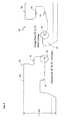
- FIG. 1 is a cross-sectional view of two floorboards according to an aspect of the invention joined by their connecting profiles extending along their edges;
- FIG. 2 is a cross-sectional view of another variant of floorboards according to an aspect of the invention.
- FIG. 3 is a cross-sectional view of a variant of the floorboards of FIG. 1 optimized for laminate flooring;
- FIG. 4 is a cross-sectional view of the floorboards of FIG. 3 in the connected state
- FIG. 5 is a cross-sectional view of LVT floorboards according to an aspect of the invention.
- FIG. 6 is a cross-sectional view of further LVT floorboards according to an aspect of the invention.
- FIG. 7 is a cross-sectional view of a thinner variant of the LVT floorboards of FIG. 6 .
- FIG. 1 illustrates an embodiment of the invention in the form of a wood or wood veneer (also called “engineered wood”) flooring system.
- FIG. 1 specifically shows the mechanical connection between a first floorboard 10 a and a second floorboard 10 b.
- Each floorboard 10 a , 10 b comprises a structural body layer 12 consisting of fibreboard (e.g. high or medium density fibreboard) or wood, a top surface layer 14 and a balancing layer 16 at the back face.
- the surface layer provides appearance and durability to the floorboards 10 a , 10 b and has a thickness comprised in the range from, e.g., 0.15 to 1 mm in case of wood veneer or 2 to 5 mm in case of parquet.
- the structural body layer typically has a thickness in the range from, e.g., 3 to 8 mm and provides stability.
- the balancing layer is intended to keep the floorboard level when environmental conditions (e.g. relative humidity, temperature) vary.
- the floorboards 10 a , 10 b are connected by complementarily shaped connecting profiles at the long and short sides of the floorboards.
- the floorboards are brought together by inserting the tip 18 of the tongue 20 of the second connecting profile 22 of the floorboard to be installed into the corresponding tongue groove 24 of the first connecting profile 26 of an already installed floorboard.
- the floorboard to be installed is held inclined with respect to the floor and then brought into its final position in a rotational and, possibly, slightly translational, movement.
- the first connecting profile 26 comprises a tongue groove 24 , which is delimited to the bottom by a protruding strip 28 .
- the protruding strip is arranged at the bottom face 30 of the floorboard 10 a and terminates in a locking element 32 that projects towards the top face 34 of the floorboard.
- the second connecting profile 22 comprises the overhanging tongue 20 , which delimits at its bottom a recess for receiving the protruding strip 28 .
- the recess comprises a locking groove 38 configured for cooperating with the locking element 32 of the protruding strip. When properly inserted into the locking groove 38 , the locking element 32 and the locking groove cooperate to provide a horizontal locking effect.
- the inwardly turned side surface 40 of the locking element 32 comes into abutment with the corresponding inwardly turned surface 42 on the bottom side of the tongue 20 , so that the joined connecting profiles are prevented from separating horizontally.
- movement is blocked by the frontal top edges 44 a , 44 b of the first and second connecting profiles being in contact with each other.
- the tongue groove 24 is configured to accommodate the tip 18 of the tongue 20 , thereby providing a vertical locking of the connected profiles.
- the tip 18 of the tongue 20 comprises an upper contact surface 46 and a lower contact surface 48 that are inclined with respect to each other.
- the (virtual) intersection axis of both surfaces 46 , 48 lies outwardly from the floorboard to which the tongue 20 belongs.
- the upper contact surface 46 is horizontal
- the lower contact surface is slanted.
- the inclination angles of the lower surface may be different on the long side and the short side of the floorboard.
- the tongue groove 24 is delimited to the top by a substantially horizontal upper delimiting surface 49 and to the bottom by an inclined lower delimiting surface 50 .
- the upper 46 and lower 48 contact surface of the overhanging tongue 20 are configured and arranged for contacting the upper 49 and lower 50 delimiting surface, respectively, of the tongue groove 24 when the connecting profiles 22 and 26 are engaged.
- FIG. 2 shows the mechanical connection between a first floorboard 110 a and a second floorboard 110 b.
- Each floorboard 110 a , 110 b comprises a structural body layer 112 consisting of fibreboard (e.g. high or medium density fibreboard) or wood, a top surface layer 114 and a balancing layer 116 at the back face.
- the thicknesses of the different layers may be as in the embodiment of FIG. 1 .
- the floorboards 110 a , 110 b are connected by complementarily shaped connecting profiles at the long and short sides of the floorboards.
- the configuration of the connecting profiles is generally the same as in the embodiment of FIG. 1 but with slight differences.
- the tongue 120 of the second connection profile 122 is similar to the tongue 20 of the embodiment of FIG. 1 but its underside is shaped slightly differently. Starting from the tip of the tongue, the slope of the underside first has a relatively steep slope, followed by a segment with a lesser slope, which forms the lower contact surface 148 of the tongue 120 . Farther away from the tip, the underside of the tongue 120 becomes substantially horizontal. The upper contact surface 146 of the tongue tip is substantially horizontal. The same is valid, mutatis mutandis, for the corresponding tongue groove 124 of the first connection profile.
- the tongue groove 124 is configured to accommodate the tip 118 of the tongue 20 , thereby providing a vertical locking of the connected profiles 122 , 126 .
- the protruding strip 128 is configured differently than that of FIG. 1 .
- the protruding strip 128 comprises a sloping upper surface 150 , which forms an angle with the lower surface 152 .
- the upper surface 150 of the stem portion of the protruding strip also provides the lower delimiting surface of the tongue groove, which enters into contact with the lower contact surface 148 of the tongue tip 118 .
- the upper delimiting surface 149 of the tongue groove 124 is provided by a substantially horizontal bottom side of the frontal top edge 144 a of the first connecting profile 126 .
- the protruding strip 128 terminates in a locking element 132 projecting towards the top face 134 of the floorboard.
- the overhanging tongue 120 of the second connecting profile 122 delimits at its bottom a recess for receiving the protruding strip 128 .
- the recess comprises a locking groove 138 configured for cooperating with the locking element 132 of the protruding strip. When properly inserted into the locking groove 138 , the locking element 132 cooperates with the locking groove 138 to provide a horizontal locking effect.
- the inwardly turned side surface 140 of the locking element 132 comes into abutment with the corresponding inwardly turned surface 142 on the bottom side of the tongue 120 , so that the joined connecting profiles are prevented from separating horizontally.
- movement is blocked by the frontal top edges 144 a , 144 b of the first and second connecting profiles being in contact with each other.
- FIG. 3 illustrates possible variations of the connecting profiles 22 and 26 of FIG. 1 to optimize them for laminate flooring: the slope of the lower surface of the tip of the so-called “fat” tongue 48 is reduced from 15° (for wood floorboard) to 13° (for laminate floorboard) and the slope of the inwardly turned side surface 40 of the locking element 132 is increased from 50° (for wood floorboard) to 75° (for laminate floorboard).
- FIG. 4 shows the variants of the connecting profiles 22 and 26 presented in FIG. 3 in the connected state.
- FIG. 5 illustrates two connection profiles particularly suited for floorboards made from LVT material.
- Each floorboard 210 a , 210 b comprises a structural vinyl body layer, a decorative top (including, e.g. a vinyl wear layer and, possibly, a urethane top coating that improves resistance to abrasion) and a balancing layer at the back face.
- the surface layer provides appearance and durability to the floorboards 210 a , 210 b .
- the balancing layer is intended to keep the floorboard level when environmental conditions (e.g. relative humidity, temperature) vary.
- the entire thickness of the LVT floorboards amounts to 5 mm.
- the floorboards 210 a , 210 b are connected by complementarily shaped connecting profiles 222 , 226 at the long and short sides of the floorboards.
- the floorboards are brought together by inserting the tip 218 of the tongue 220 of the second connecting profile 222 of the floorboard to be installed into the corresponding tongue groove 224 of the first connecting profile 226 of an already installed floorboard.
- the floorboard to be installed is held inclined with respect to the floor and then brought into its final position in a rotational and, possibly, slightly translational, movement.
- the first connecting profile 226 comprises a tongue groove 224 , which is delimited to the bottom by a protruding strip 228 .
- the protruding strip 228 is arranged at the bottom face 230 of the floorboard 210 a and terminates in a locking element 232 projecting towards the top face 234 of the floorboard.
- the second connecting profile 222 comprises the overhanging tongue 220 , which delimits at its bottom a recess for receiving the protruding strip 228 .
- the recess comprises a locking groove 238 configured for cooperating with the locking element 232 of the protruding strip.
- the locking element 232 When properly inserted into the locking groove 238 , the locking element 232 cooperates with the locking groove 238 to provide a horizontal locking effect. Specifically, the inwardly turned side surface 240 of the locking element 232 comes into abutment with the corresponding inwardly turned surface 242 on the bottom side of the tongue 220 , so that the joined connecting profiles are prevented from separating horizontally. In the opposite direction, movement is blocked by the frontal top edges 244 a , 244 b of the first and second connecting profiles being in contact with each other.
- the tongue groove 224 is configured to accommodate the tip 218 of the tongue 220 , thereby providing a vertical locking of the connected profiles.
- the tongue 220 comprises an upper contact surface 246 and a lower contact surface 248 that are inclined with respect to each other.
- the (virtual) intersection axis A of both surfaces 246 , 248 lies outside of the floorboard to which the tongue 220 belongs.
- the tongue groove 224 is delimited to the top by an upper delimiting surface 249 having the same slope as contact surface 246 and to the bottom by a substantially horizontal lower delimiting surface 250 .
- the upper 246 and lower 248 contact surface of the overhanging tongue 220 are configured and arranged for contacting the upper 249 and lower 250 delimiting surface, respectively, of the tongue groove 224 when the connecting profiles 222 and 226 are engaged.
- the tip 218 of the tongue 220 and the corresponding tongue groove 224 have a height corresponding approximately to one third of the entire thickness of the LVT floorboard. Both the tip 218 and the tongue groove 224 are located approximately in the middle of the height of the LVT floorboard.
- FIG. 6 shows alternative connection profiles particularly suited for floorboards made from LVT material.
- the floorboards 310 a , 310 b are connected by complementarily shaped connecting profiles at the long and short sides of the floorboards.
- the configuration of the connecting profiles is generally the same as in the embodiment of FIG. 5 but with some differences, which are discussed below.
- the tongue 320 of the second connecting profile 322 has a horizontal upper contact surface 346 and an inclined lower contact surface 348 .
- the protruding strip 328 of the first connecting profile 326 is configured differently than that of FIG. 5 .
- the protruding strip 328 comprises a sloping upper surface 350 , which provides the lower delimiting surface of the tongue groove 324 .
- the tongue groove 324 is delimited to the top by a substantially horizontal upper delimiting surface 349 .
- the (virtual) intersection axis A′ of both surfaces 346 , 348 lies outwardly from the floorboard to which the tongue 320 belongs.
- FIG. 7 shows a variant of the LVT floorboards of FIG. 6 with reduced overall thickness.
- the connecting profiles 326 and 322 are identically shaped. The reader is thus invited to refer to the description above for details thereon.
Priority Applications (1)
| Application Number | Priority Date | Filing Date | Title |
|---|---|---|---|
| US15/735,805 US10480199B2 (en) | 2015-06-26 | 2016-06-22 | Floorboards with horizontally and vertically locking connecting profiles |
Applications Claiming Priority (3)
| Application Number | Priority Date | Filing Date | Title |
|---|---|---|---|
| US201562185187P | 2015-06-26 | 2015-06-26 | |
| PCT/EP2016/064478 WO2016207251A1 (en) | 2015-06-26 | 2016-06-22 | Floorboards with horizontally and vertically locking connecting profiles |
| US15/735,805 US10480199B2 (en) | 2015-06-26 | 2016-06-22 | Floorboards with horizontally and vertically locking connecting profiles |
Publications (2)
| Publication Number | Publication Date |
|---|---|
| US20190106887A1 US20190106887A1 (en) | 2019-04-11 |
| US10480199B2 true US10480199B2 (en) | 2019-11-19 |
Family
ID=56178371
Family Applications (1)
| Application Number | Title | Priority Date | Filing Date |
|---|---|---|---|
| US15/735,805 Active US10480199B2 (en) | 2015-06-26 | 2016-06-22 | Floorboards with horizontally and vertically locking connecting profiles |
Country Status (5)
| Country | Link |
|---|---|
| US (1) | US10480199B2 (ru) |
| EP (1) | EP3314070A1 (ru) |
| CN (1) | CN107646060B (ru) |
| RU (1) | RU2704162C2 (ru) |
| WO (1) | WO2016207251A1 (ru) |
Families Citing this family (3)
| Publication number | Priority date | Publication date | Assignee | Title |
|---|---|---|---|---|
| CA3209449A1 (en) * | 2010-01-11 | 2011-07-14 | Valinge Innovation Ab | Floor covering with interlocking design |
| PT3447210T (pt) * | 2017-08-23 | 2021-07-30 | Flooring Ind Ltd Sarl | Painel de piso para formar um revestimento de piso |
| BE1027789B1 (nl) * | 2019-11-25 | 2021-06-22 | Flooring Ind Ltd Sarl | Paneel met koppeldelen |
Citations (17)
| Publication number | Priority date | Publication date | Assignee | Title |
|---|---|---|---|---|
| US20020020127A1 (en) * | 2000-06-20 | 2002-02-21 | Thiers Bernard Paul Joseph | Floor covering |
| US20030024200A1 (en) * | 1996-06-11 | 2003-02-06 | Unilin Beheer B.V., Besloten Vennootschap | Floor panels with edge connectors |
| WO2004016876A2 (de) | 2002-07-19 | 2004-02-26 | Leitz Gmbh & Co Kg | Verbindungsprofil für plattenartige paneelen |
| US20050166514A1 (en) * | 2004-01-13 | 2005-08-04 | Valinge Aluminium Ab | Floor covering and locking systems |
| US20060156672A1 (en) * | 2004-12-23 | 2006-07-20 | Meersseman Laurent | Floor panel, as well as method, device and accessories for manufacturing such floor panel |
| US20060260254A1 (en) * | 2005-05-20 | 2006-11-23 | Valinge Aluminium Ab | Mechanical Locking System For Floor Panels |
| DE102005043721A1 (de) | 2005-09-13 | 2007-04-05 | Witex Ag | Fussbodenkonstruktion |
| WO2009077178A1 (de) * | 2007-12-18 | 2009-06-25 | Kaindl Flooring Gmbh | Verkleidungspaneel und daraus gebildete verkleidung |
| US20090193741A1 (en) * | 2006-06-02 | 2009-08-06 | Mark Cappelle | Floor covering, floor element and method for manufacturing floor elements |
| US20090260313A1 (en) * | 2006-04-06 | 2009-10-22 | Flooring Industries Limited | Method for manufacturing floor panels and floor panel |
| US7841150B2 (en) | 2002-04-03 | 2010-11-30 | Valinge Innovation Ab | Mechanical locking system for floorboards |
| US7892617B2 (en) | 2005-06-14 | 2011-02-22 | Tarkett Sas | Panel, in particular for floor covering |
| WO2011028171A1 (en) | 2009-09-04 | 2011-03-10 | Välinge Innovation AB | A method of assembling resilient floorboards which are provided with a mechanical locking system |
| US20110131916A1 (en) * | 2009-12-04 | 2011-06-09 | Mannington Mills, Inc. | Connecting System For Surface Coverings |
| US8261508B2 (en) * | 2006-10-31 | 2012-09-11 | Flooring Industries Limited, Sarl | Floor panel and floor covering consisting of such floor panels |
| US20130309441A1 (en) * | 2011-01-28 | 2013-11-21 | Akzenta Paneele + Profile Gmbh | Panel |
| WO2016042142A1 (en) * | 2014-09-18 | 2016-03-24 | Tarkett Gdl | Thin decorative surface covering |
Family Cites Families (5)
| Publication number | Priority date | Publication date | Assignee | Title |
|---|---|---|---|---|
| KR100380660B1 (ko) * | 2000-11-22 | 2003-04-18 | 학교법인 성균관대학 | 중성빔을 이용한 반도체소자의 식각방법 및 이를 위한식각장치 |
| BRPI0504155A (pt) * | 2005-05-25 | 2007-01-23 | Rodolfo Dafico Bernar Oliveira | processo de fabricação de artefatos extrusados ou moldados por compressão de alumino-silicatos naturais e agregados em meio alcalino com pequeno tempo de cura e alta eficiência térmica |
| BE1017232A6 (nl) * | 2006-07-19 | 2008-05-06 | Flooring Ind Ltd | Werkwijze voor het vervaardigen van vloerpanelen, vloerpanelen volgens deze werkwijze verkregen en set van gereedschappen hierbij aangewend. |
| US7774417B2 (en) * | 2007-09-13 | 2010-08-10 | International Business Machines Corporation | Method and system for sequencing of electronic mail to derive a specified response trajectory |
| US9202111B2 (en) * | 2011-01-09 | 2015-12-01 | Fitbit, Inc. | Fitness monitoring device with user engagement metric functionality |
-
2016
- 2016-06-22 WO PCT/EP2016/064478 patent/WO2016207251A1/en active Application Filing
- 2016-06-22 US US15/735,805 patent/US10480199B2/en active Active
- 2016-06-22 CN CN201680028128.6A patent/CN107646060B/zh active Active
- 2016-06-22 EP EP16731166.1A patent/EP3314070A1/en active Pending
- 2016-06-22 RU RU2018101979A patent/RU2704162C2/ru active
Patent Citations (19)
| Publication number | Priority date | Publication date | Assignee | Title |
|---|---|---|---|---|
| EP1898026A2 (en) | 1996-06-11 | 2008-03-12 | Unilin Beheer B.V. | Hard floor panel with integrated mechanical locking means |
| US20030024200A1 (en) * | 1996-06-11 | 2003-02-06 | Unilin Beheer B.V., Besloten Vennootschap | Floor panels with edge connectors |
| US20020020127A1 (en) * | 2000-06-20 | 2002-02-21 | Thiers Bernard Paul Joseph | Floor covering |
| EP2275615A2 (en) | 2000-06-20 | 2011-01-19 | Flooring Industries Ltd. | Floor covering consisting of hard panels |
| US7841150B2 (en) | 2002-04-03 | 2010-11-30 | Valinge Innovation Ab | Mechanical locking system for floorboards |
| WO2004016876A2 (de) | 2002-07-19 | 2004-02-26 | Leitz Gmbh & Co Kg | Verbindungsprofil für plattenartige paneelen |
| US20050166514A1 (en) * | 2004-01-13 | 2005-08-04 | Valinge Aluminium Ab | Floor covering and locking systems |
| US20060156672A1 (en) * | 2004-12-23 | 2006-07-20 | Meersseman Laurent | Floor panel, as well as method, device and accessories for manufacturing such floor panel |
| US20060260254A1 (en) * | 2005-05-20 | 2006-11-23 | Valinge Aluminium Ab | Mechanical Locking System For Floor Panels |
| US7892617B2 (en) | 2005-06-14 | 2011-02-22 | Tarkett Sas | Panel, in particular for floor covering |
| DE102005043721A1 (de) | 2005-09-13 | 2007-04-05 | Witex Ag | Fussbodenkonstruktion |
| US20090260313A1 (en) * | 2006-04-06 | 2009-10-22 | Flooring Industries Limited | Method for manufacturing floor panels and floor panel |
| US20090193741A1 (en) * | 2006-06-02 | 2009-08-06 | Mark Cappelle | Floor covering, floor element and method for manufacturing floor elements |
| US8261508B2 (en) * | 2006-10-31 | 2012-09-11 | Flooring Industries Limited, Sarl | Floor panel and floor covering consisting of such floor panels |
| WO2009077178A1 (de) * | 2007-12-18 | 2009-06-25 | Kaindl Flooring Gmbh | Verkleidungspaneel und daraus gebildete verkleidung |
| WO2011028171A1 (en) | 2009-09-04 | 2011-03-10 | Välinge Innovation AB | A method of assembling resilient floorboards which are provided with a mechanical locking system |
| US20110131916A1 (en) * | 2009-12-04 | 2011-06-09 | Mannington Mills, Inc. | Connecting System For Surface Coverings |
| US20130309441A1 (en) * | 2011-01-28 | 2013-11-21 | Akzenta Paneele + Profile Gmbh | Panel |
| WO2016042142A1 (en) * | 2014-09-18 | 2016-03-24 | Tarkett Gdl | Thin decorative surface covering |
Also Published As
| Publication number | Publication date |
|---|---|
| WO2016207251A1 (en) | 2016-12-29 |
| RU2018101979A3 (ru) | 2019-07-26 |
| US20190106887A1 (en) | 2019-04-11 |
| RU2704162C2 (ru) | 2019-10-24 |
| CN107646060B (zh) | 2021-01-26 |
| EP3314070A1 (en) | 2018-05-02 |
| RU2018101979A (ru) | 2019-07-26 |
| CN107646060A (zh) | 2018-01-30 |
Similar Documents
| Publication | Publication Date | Title |
|---|---|---|
| US10655339B2 (en) | Mechanical locking system for panels and method of installing same | |
| US20200087927A1 (en) | Mechanical locking system for floor panels | |
| US7802411B2 (en) | Mechanical locking system for floor panels | |
| EP1650375B1 (en) | A set of floor panels | |
| US8429870B2 (en) | Connecting system for surface coverings | |
| US9322183B2 (en) | Floor covering and locking systems | |
| RU2603987C2 (ru) | Система механического замкового соединения для панелей напольных покрытий | |
| US8857126B2 (en) | Mechanical locking system for floor panels | |
| US20050166514A1 (en) | Floor covering and locking systems | |
| US11168482B2 (en) | Panel | |
| KR20140053168A (ko) | 바닥 패널용 기계식 로킹 시스템 | |
| US10480199B2 (en) | Floorboards with horizontally and vertically locking connecting profiles | |
| US11976470B2 (en) | Hard floor panel for floating installation with the formation of a flooring panel network | |
| CA3056031A1 (en) | Floor panel for forming a floor covering |
Legal Events
| Date | Code | Title | Description |
|---|---|---|---|
| FEPP | Fee payment procedure |
Free format text: ENTITY STATUS SET TO UNDISCOUNTED (ORIGINAL EVENT CODE: BIG.); ENTITY STATUS OF PATENT OWNER: LARGE ENTITY |
|
| AS | Assignment |
Owner name: TARKETT GDL S.A., LUXEMBOURG Free format text: ASSIGNMENT OF ASSIGNORS INTEREST;ASSIGNOR:SIMON, JEAN-YVES;REEL/FRAME:045176/0893 Effective date: 20171213 |
|
| STPP | Information on status: patent application and granting procedure in general |
Free format text: RESPONSE TO NON-FINAL OFFICE ACTION ENTERED AND FORWARDED TO EXAMINER |
|
| STPP | Information on status: patent application and granting procedure in general |
Free format text: NOTICE OF ALLOWANCE MAILED -- APPLICATION RECEIVED IN OFFICE OF PUBLICATIONS |
|
| STPP | Information on status: patent application and granting procedure in general |
Free format text: PUBLICATIONS -- ISSUE FEE PAYMENT VERIFIED |
|
| STCF | Information on status: patent grant |
Free format text: PATENTED CASE |
|
| MAFP | Maintenance fee payment |
Free format text: PAYMENT OF MAINTENANCE FEE, 4TH YEAR, LARGE ENTITY (ORIGINAL EVENT CODE: M1551); ENTITY STATUS OF PATENT OWNER: LARGE ENTITY Year of fee payment: 4 |