US10478917B2 - Hybrid laser welding system and method using two robots - Google Patents
Hybrid laser welding system and method using two robots Download PDFInfo
- Publication number
- US10478917B2 US10478917B2 US15/124,770 US201515124770A US10478917B2 US 10478917 B2 US10478917 B2 US 10478917B2 US 201515124770 A US201515124770 A US 201515124770A US 10478917 B2 US10478917 B2 US 10478917B2
- Authority
- US
- United States
- Prior art keywords
- welding
- joint
- trajectory
- manipulator
- welding device
- Prior art date
- Legal status (The legal status is an assumption and is not a legal conclusion. Google has not performed a legal analysis and makes no representation as to the accuracy of the status listed.)
- Active, expires
Links
Images


Classifications
-
- B—PERFORMING OPERATIONS; TRANSPORTING
- B23—MACHINE TOOLS; METAL-WORKING NOT OTHERWISE PROVIDED FOR
- B23K—SOLDERING OR UNSOLDERING; WELDING; CLADDING OR PLATING BY SOLDERING OR WELDING; CUTTING BY APPLYING HEAT LOCALLY, e.g. FLAME CUTTING; WORKING BY LASER BEAM
- B23K26/00—Working by laser beam, e.g. welding, cutting or boring
- B23K26/02—Positioning or observing the workpiece, e.g. with respect to the point of impact; Aligning, aiming or focusing the laser beam
- B23K26/04—Automatically aligning, aiming or focusing the laser beam, e.g. using the back-scattered light
- B23K26/044—Seam tracking
-
- B—PERFORMING OPERATIONS; TRANSPORTING
- B23—MACHINE TOOLS; METAL-WORKING NOT OTHERWISE PROVIDED FOR
- B23K—SOLDERING OR UNSOLDERING; WELDING; CLADDING OR PLATING BY SOLDERING OR WELDING; CUTTING BY APPLYING HEAT LOCALLY, e.g. FLAME CUTTING; WORKING BY LASER BEAM
- B23K10/00—Welding or cutting by means of a plasma
- B23K10/02—Plasma welding
-
- B—PERFORMING OPERATIONS; TRANSPORTING
- B23—MACHINE TOOLS; METAL-WORKING NOT OTHERWISE PROVIDED FOR
- B23K—SOLDERING OR UNSOLDERING; WELDING; CLADDING OR PLATING BY SOLDERING OR WELDING; CUTTING BY APPLYING HEAT LOCALLY, e.g. FLAME CUTTING; WORKING BY LASER BEAM
- B23K15/00—Electron-beam welding or cutting
- B23K15/0046—Welding
- B23K15/0053—Seam welding
- B23K15/006—Seam welding of rectilinear seams
-
- B—PERFORMING OPERATIONS; TRANSPORTING
- B23—MACHINE TOOLS; METAL-WORKING NOT OTHERWISE PROVIDED FOR
- B23K—SOLDERING OR UNSOLDERING; WELDING; CLADDING OR PLATING BY SOLDERING OR WELDING; CUTTING BY APPLYING HEAT LOCALLY, e.g. FLAME CUTTING; WORKING BY LASER BEAM
- B23K26/00—Working by laser beam, e.g. welding, cutting or boring
- B23K26/08—Devices involving relative movement between laser beam and workpiece
- B23K26/0869—Devices involving movement of the laser head in at least one axial direction
- B23K26/0876—Devices involving movement of the laser head in at least one axial direction in at least two axial directions
- B23K26/0884—Devices involving movement of the laser head in at least one axial direction in at least two axial directions in at least three axial directions, e.g. manipulators, robots
-
- B—PERFORMING OPERATIONS; TRANSPORTING
- B23—MACHINE TOOLS; METAL-WORKING NOT OTHERWISE PROVIDED FOR
- B23K—SOLDERING OR UNSOLDERING; WELDING; CLADDING OR PLATING BY SOLDERING OR WELDING; CUTTING BY APPLYING HEAT LOCALLY, e.g. FLAME CUTTING; WORKING BY LASER BEAM
- B23K26/00—Working by laser beam, e.g. welding, cutting or boring
- B23K26/346—Working by laser beam, e.g. welding, cutting or boring in combination with welding or cutting covered by groups B23K5/00 - B23K25/00, e.g. in combination with resistance welding
- B23K26/348—Working by laser beam, e.g. welding, cutting or boring in combination with welding or cutting covered by groups B23K5/00 - B23K25/00, e.g. in combination with resistance welding in combination with arc heating, e.g. tungsten inert gas [TIG], metal inert gas [MIG] or plasma welding
-
- B—PERFORMING OPERATIONS; TRANSPORTING
- B23—MACHINE TOOLS; METAL-WORKING NOT OTHERWISE PROVIDED FOR
- B23K—SOLDERING OR UNSOLDERING; WELDING; CLADDING OR PLATING BY SOLDERING OR WELDING; CUTTING BY APPLYING HEAT LOCALLY, e.g. FLAME CUTTING; WORKING BY LASER BEAM
- B23K28/00—Welding or cutting not covered by groups B23K5/00 - B23K26/00
- B23K28/02—Combined welding or cutting procedures or apparatus
-
- B—PERFORMING OPERATIONS; TRANSPORTING
- B23—MACHINE TOOLS; METAL-WORKING NOT OTHERWISE PROVIDED FOR
- B23K—SOLDERING OR UNSOLDERING; WELDING; CLADDING OR PLATING BY SOLDERING OR WELDING; CUTTING BY APPLYING HEAT LOCALLY, e.g. FLAME CUTTING; WORKING BY LASER BEAM
- B23K37/00—Auxiliary devices or processes, not specially adapted for a procedure covered by only one of the other main groups of this subclass
- B23K37/02—Carriages for supporting the welding or cutting element
-
- B—PERFORMING OPERATIONS; TRANSPORTING
- B23—MACHINE TOOLS; METAL-WORKING NOT OTHERWISE PROVIDED FOR
- B23K—SOLDERING OR UNSOLDERING; WELDING; CLADDING OR PLATING BY SOLDERING OR WELDING; CUTTING BY APPLYING HEAT LOCALLY, e.g. FLAME CUTTING; WORKING BY LASER BEAM
- B23K9/00—Arc welding or cutting
- B23K9/16—Arc welding or cutting making use of shielding gas
- B23K9/167—Arc welding or cutting making use of shielding gas and of a non-consumable electrode
-
- B—PERFORMING OPERATIONS; TRANSPORTING
- B23—MACHINE TOOLS; METAL-WORKING NOT OTHERWISE PROVIDED FOR
- B23K—SOLDERING OR UNSOLDERING; WELDING; CLADDING OR PLATING BY SOLDERING OR WELDING; CUTTING BY APPLYING HEAT LOCALLY, e.g. FLAME CUTTING; WORKING BY LASER BEAM
- B23K9/00—Arc welding or cutting
- B23K9/16—Arc welding or cutting making use of shielding gas
- B23K9/173—Arc welding or cutting making use of shielding gas and of a consumable electrode
-
- B—PERFORMING OPERATIONS; TRANSPORTING
- B25—HAND TOOLS; PORTABLE POWER-DRIVEN TOOLS; MANIPULATORS
- B25J—MANIPULATORS; CHAMBERS PROVIDED WITH MANIPULATION DEVICES
- B25J19/00—Accessories fitted to manipulators, e.g. for monitoring, for viewing; Safety devices combined with or specially adapted for use in connection with manipulators
- B25J19/02—Sensing devices
- B25J19/021—Optical sensing devices
- B25J19/023—Optical sensing devices including video camera means
-
- B—PERFORMING OPERATIONS; TRANSPORTING
- B25—HAND TOOLS; PORTABLE POWER-DRIVEN TOOLS; MANIPULATORS
- B25J—MANIPULATORS; CHAMBERS PROVIDED WITH MANIPULATION DEVICES
- B25J9/00—Program-controlled manipulators
- B25J9/16—Program controls
- B25J9/1679—Program controls characterised by the tasks executed
- B25J9/1682—Dual arm manipulator; Coordination of several manipulators
-
- G—PHYSICS
- G05—CONTROLLING; REGULATING
- G05B—CONTROL OR REGULATING SYSTEMS IN GENERAL; FUNCTIONAL ELEMENTS OF SUCH SYSTEMS; MONITORING OR TESTING ARRANGEMENTS FOR SUCH SYSTEMS OR ELEMENTS
- G05B2219/00—Program-control systems
- G05B2219/30—Nc systems
- G05B2219/39—Robotics, robotics to robotics hand
- G05B2219/39121—Two manipulators operate on same object
-
- G—PHYSICS
- G05—CONTROLLING; REGULATING
- G05B—CONTROL OR REGULATING SYSTEMS IN GENERAL; FUNCTIONAL ELEMENTS OF SUCH SYSTEMS; MONITORING OR TESTING ARRANGEMENTS FOR SUCH SYSTEMS OR ELEMENTS
- G05B2219/00—Program-control systems
- G05B2219/30—Nc systems
- G05B2219/39—Robotics, robotics to robotics hand
- G05B2219/39243—Adaptive trajectory tracking
-
- G—PHYSICS
- G05—CONTROLLING; REGULATING
- G05B—CONTROL OR REGULATING SYSTEMS IN GENERAL; FUNCTIONAL ELEMENTS OF SUCH SYSTEMS; MONITORING OR TESTING ARRANGEMENTS FOR SUCH SYSTEMS OR ELEMENTS
- G05B2219/00—Program-control systems
- G05B2219/30—Nc systems
- G05B2219/45—Nc applications
- G05B2219/45104—Lasrobot, welding robot
Definitions
- the present invention generally relates to the field of welding systems and welding methods. More specifically, the invention relates to a hybrid laser welding system and method that uses two robots.
- Automated hybrid laser/arc welding typically uses a laser welding device in combination with a conventional arc welding device. Both the laser welding device and the arc welding device are mounted together on a robot. The laser is aimed at the components to be welded and the laser basically melts surrounding a welding joint while the arc follows, filling the gap with new material.
- a welding system comprising a first and a second manipulator, respectively having a first and a second welding head, and a controller.
- the first welding head which is connected to the first manipulator, has a joint detection device and a first welding device.
- the joint detection device is operative to read welding joint characteristics, such as a joint type or a gap between components to be welded, along a welding joint.
- the second welding head which is connected to the second manipulator, is equipped with a second welding device.
- the controller is in communication with both the first and the second manipulators as well as with the joint detection device.
- the controller determines a corrected trajectory based on a predetermined welding trajectory and on the welding joint characteristics read by the joint detection device.
- the controller communicates the corrected trajectory with a first time delay to the first manipulator and communicates the corrected trajectory with a second time delay to the second manipulator.
- the second time delay is a function of a distance between the joint detection device and the second welding device.
- the controller is operative to make the joint detection device follow the predetermined trajectory and to make the first and the second welding devices follow the corrected trajectory.
- the second time delay is longer that the first time delay.
- the controller is adapted to electronically store the predetermined welding trajectory. Moreover, the controller determines the second time delay so that in operation the first welding device and the second welding device each have a point of action located at a predetermined distance from each other.
- the first corrected trajectory may further be based on characteristics of the first welding device.
- the second corrected trajectory may further be based on characteristics of the second welding device.
- the first welding device is typically of a laser type while the second welding device is typically of an electrode type, the characteristics of the first welding device are different from the characteristics of the second welding device.
- the first welding head may comprise a pivot, the first welding device being mounted to the pivot so that the first welding device may be pivoted with respect to the joint detection device.
- a method for welding components along a welding joint comprises independently controlling with the two independent manipulators the first welding device and the second welding device by moving the first welding device along the corrected trajectory and by moving the second welding device along the corrected trajectory after a time delay.
- This corrected trajectory is based on a predetermined welding trajectory and on welding joint characteristics detected by the joint detection device.
- the time delay is a function of the distance between the joint detection device and the second welding device.
- a method for welding components along a welding joint comprises:
- the second time delay is longer than the first time delay so that the second welding device is made to follow the first welding device.
- the method may further comprise assessing the distance between the first welding device and the second welding device. This assessing may be done at either regular time intervals or regular distance intervals travelled by the first welding device.
- the method may further comprise pivoting the first welding device with respect to the joint detection device.
- FIG. 1 is an isometric view of a welding system in accordance with an embodiment
- FIG. 2 is an isometric view of a detail of a first welding head of the welding system of FIG. 1 ;
- FIG. 3 is a schematic view of a communication system between different elements of the welding system of FIG. 1 ;
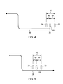
- FIG. 4 is a schematic view of the first and second welding heads as they are positioned at a start of a welding joint in accordance with an embodiment
- FIG. 5 is a schematic view of the first and second welding heads as they are positioned along the welding joint of FIG. 4 ;
- FIG. 6 is a schematic view of trajectories sent to manipulators of the welding system of FIG. 1 .
- FIG. 7 is a flowchart of the process followed by a controller to control the manipulators of the welding system of FIG. 1 .
- the present invention relates to an adaptive hybrid laser/arc welding system and method that uses two robots to which are mounted two separate welding heads.
- a joint detection device is mounted to one of the welding head so as to read characteristics of a welding joint.
- a controller uses the readings of the welding joint characteristics to correct a predetermined welding trajectory and sends the information to at least one of the two robots.
- This hybrid laser/arc welding system allows reaching welding areas which are usually difficult to reach and following welding paths that are usually impossible to follow with a system where both welding heads are mounted on a single robot while maintaining the real-time adaptability of the welding system.
- FIG. 1 depicts a welding system 10 .
- the welding system 10 comprises a first manipulator 12 and a second manipulator 14 .
- Each one of the first and the second manipulators 12 , 14 are respectively equipped with a first welding head 16 and a second welding head 18 .
- a controller 20 is in communication with both the first manipulator 12 and the second manipulator 14 .
- the first and second manipulators 12 , 14 are typically industrial robots such as the ones manufactured by companies like Kuka or Fanuc and are well known in the art.
- the first welding head 16 also comprises a joint detection device 24 .
- the first welding head 16 may also comprise a pivot 28 to which is mounted the first welding device 22 so that it may be independently pivoted with respect to the joint detection device 24 . This allows to better reach a material of the components to be welded 30 along the welding joint 26 . A detail of this arrangement is also shown in FIG. 2 .
- the second welding head 18 connected to the second manipulator 14 , is equipped with a second welding device 32 .
- the second welding device 32 is typically of an electrode type such as GMAW, GTAW, PAW, SMAW or any other electrode type well known in the art.
- the role of the second welding device 32 is to add filler material 33 to a weld pool created between the components to be welded 30 .
- FIG. 3 is now concurrently referred to. Different communication connections between elements will now be described. It is envisioned that these connections may be wired or wireless, but are nevertheless schematically represented in the attached figures by lines between elements.
- the controller 20 is connected to the first manipulator 12 to control its movements, and thereby the movements of the first welding head 16 , the first welding device 22 and the joint detection device 24 .
- the controller 20 is also connected to the joint detection device 24 and to the first welding device 22 so as to control and obtain feedback and information from them such as welding joint characteristics.
- the controller 20 has a predetermined representation of the welding joint trajectory that is electronically stored in its memory.
- this predetermined welding trajectory 34 may be remotely stored and be accessible by the controller 20 through any other access such as USB, remote, Wi-Fi or cloud access.
- the controller 20 is operative to determine a first corrected trajectory.
- the controller 20 is connected to the second manipulator 14 and controls its movement, and thereby the movements of the second welding head 18 and that of the second welding device 32 .
- the controller 20 may also be connected to the second welding device 32 so as to adjust its parameters.
- the controller 20 is operative to determine a second corrected trajectory based on the predetermined welding trajectory 34 , on the welding joint characteristics and on a distance between the first welding device 22 and the second welding device 32 . This distance may be predetermined or continuously adapted during the welding process.
- the controller 20 also requires access to the predetermined welding trajectory. Similarly to the controller 20 , the controller 20 may access the predetermined welding trajectory by either having it electronically stored in its memory, or by remotely accessing it through USB, remote, Wi-Fi or cloud access or even by being in communication with the controller 20 and receiving it from it.
- the joint detection device 24 is typically a camera combined with recognition software.
- the joint detection device 24 is used to detect welding joint characteristics and feed this information back to the controller 20 .
- the joint detection device 24 may also be connected to the controller 20 to feed the same information.
- FIG. 4 and FIG. 7 are now concurrently referred to.
- the components to be welded 30 are first positioned on a welding fixture 36 so that the welding joint 26 is always located in a repeatable location with respect to the first and second manipulators 12 , 14 .
- the controller 20 directs the first manipulator 12 so that the joint detection device 24 is directed to a welding joint start 38 according to the predetermined welding trajectory 34 and may read the real position of the start of the welding joint 26 at 102 .
- the joint detection device 24 keeps on reading the real position of the weld joint 26 .
- the controller 20 starts calculating a corrected welding trajectory 44 at 104 , as will be described in more details below.
- the controller 20 then directs the second manipulator 14 to place the second welding device 32 behind the first welding device 22 at a first distance 40 at 108 .
- This first distance 40 is initially set at a predetermined value. Typically, the first distance 40 is initially set at a value in the order of 5 to 50 mm.
- FIG. 5 now concurrently referred to, represents the first and the second welding devices 22 , 32 as they are in the process of welding the components to be welded 30 along the welding joint 26 .
- the first welding device 22 and the second welding device 32 are separated by the first distance 40 .
- This distance is dependent on the physical space available between the first and the second welding devices 22 , 32 , of the desired welding speed and on the desired characteristics of the weld to be performed between the components to be welded 30 .
- the first distance 40 may be calculated so that the point of actions of both the first and the second welding devices 22 , 32 are within a common welding pool.
- the first distance 40 may vary as a function of many parameters, such as welding speed, weld joint characteristics, welding joint topology, welding parameters, etc.
- the controller 20 sends to the first welding device 22 and to the first manipulator 12 the command to weld along the first corrected trajectory 46 .
- the joint detection device 24 keeps on reading the real position of the welding joint 26 as well as its characteristics. These readings are taken at constant time intervals (for example, every 0.075 sec) and continuously sent to the controller 20 and stored in its memory at 114 . This information is communicated to the controller 20 as joint readings 42 .
- the joint readings 42 comprise information about the real position of the welding joint 26 , information about a gap or a mismatch between the components to be welded 30 , as well as information about characteristics of the weld joint 26 .
- These characteristics may include information such as the type of welding joint (filet, end-to-end, corner, overlap, butt, bevel, J, etc).
- the controller 20 calculates a series of corresponding corrected points used to determine the corrected welding trajectory 44 at 104 . These corrected points are also stored in the controller's 20 memory at 105 as the corrected welding trajectory 44 .
- the corrected welding trajectory 44 has a profile which is followed by the first and the second welding devices 22 , 32 , albeit determined differently for both welding devices as is detailed below.
- the predetermined welding trajectory 34 and the corrected welding trajectory 44 are depicted in FIG. 6 , now concurrently referred to.
- the first welding head 16 Since the first welding head 16 carries both the joint detection device 24 and the first welding head 22 which are located at a second distance 45 from each other, the first welding head 16 must be controlled in such a way that the joint detecting device 24 keeps on following the predetermined welding trajectory 34 while the first welding device 22 follows a first corrected trajectory 46 .
- This is usually performed with native softwares from manipulators manufacturers.
- the first corrected trajectory 46 is in fact the corrected welding trajectory 44 which is transmitted to the first manipulator 12 with a first time delay 48 . Determination of the first corrected trajectory 46 is done at 109 and continues as long as the joint detection device 24 detects the welding joint 26 .
- This first time delay 48 compensates for the fact that the joint detection device 24 and the first welding device 22 are not located at the same place in time due to the second distance 45 between them.
- the first corrected trajectory 46 is sent by the controller 20 to the first manipulator 12 in the form of a first corrected trajectory signal 50 so that the first manipulator 12 may correctly position the first welding device 22 over the welding joint 26 .
- the controller 20 may also send a first welding parameters signal 52 to adjust the welding parameters of the first welding device 22 .
- the welding parameters of the first welding device 22 may include information such as power, position, angle, etc.
- a second time delay 54 must be added to the corrected trajectory 34 when a second corrected trajectory 56 is communicated by the controller 20 to the second manipulator 14 at 114 .
- This second time delay 54 is determined using the speed of the first and second welding devices 22 , 32 and the total distance 57 between the joint detection device 24 and the second welding device 32 , where this total distance 57 is the sum of the second distance 45 and the first distance 40 .
- the second corrected trajectory 56 is sent in the form of a second corrected trajectory signal 58 to the second manipulator 14 .
- the controller 20 sends to the second welding device 32 and to the second manipulator 14 the command to weld along the second corrected trajectory 56 .
- the controller 20 may also send a second welding parameters signal 60 to adjust the welding parameters of the second welding device 32 .
- the welding parameters of the second welding device 32 may include information such as welding current, welding voltage, material feeding rate, etc.
- the second corrected trajectory 56 could be determined using the first corrected trajectory 46 and adding to it a delay corresponding to the first distance 40 .
- first distance 40 may be affected by the precision in speed and trajectory of the first and the second manipulators 12 and 14 , it may be preferable to continuously assess the first distance 40 , for example at regular time intervals, and adjust it depending on welding conditions (for example welding joint type or gap size between the components to be welded 30 ), characteristics of the first and second welding devices 22 , 32 , or characteristics of the welding joint 26 , etc. Consequently, the second time delay 54 may be continuously adjusted and varied so as to ensure that the point of action of both the first and the second welding devices 22 , 32 is within the same fusion bath.
- the controller 12 adds a flag to the corrected welding trajectory 44 at 116 .
- this flag is either added to the first welding joint 26 detected by the controller 12 , either in the first corrected trajectory 46 or in the second corrected trajectory 56 at 117 , it respectively stops the welding operation of the first welding device 22 at 118 or of the second welding device at 120 .
Landscapes
- Engineering & Computer Science (AREA)
- Physics & Mathematics (AREA)
- Mechanical Engineering (AREA)
- Optics & Photonics (AREA)
- Plasma & Fusion (AREA)
- Robotics (AREA)
- Multimedia (AREA)
- Manipulator (AREA)
- Laser Beam Processing (AREA)
- Numerical Control (AREA)
Priority Applications (1)
| Application Number | Priority Date | Filing Date | Title |
|---|---|---|---|
| US15/124,770 US10478917B2 (en) | 2014-03-17 | 2015-03-16 | Hybrid laser welding system and method using two robots |
Applications Claiming Priority (3)
| Application Number | Priority Date | Filing Date | Title |
|---|---|---|---|
| US201461953996P | 2014-03-17 | 2014-03-17 | |
| PCT/CA2015/000165 WO2015139116A1 (en) | 2014-03-17 | 2015-03-16 | Hybrid laser welding system and method using two robots |
| US15/124,770 US10478917B2 (en) | 2014-03-17 | 2015-03-16 | Hybrid laser welding system and method using two robots |
Publications (2)
| Publication Number | Publication Date |
|---|---|
| US20170072507A1 US20170072507A1 (en) | 2017-03-16 |
| US10478917B2 true US10478917B2 (en) | 2019-11-19 |
Family
ID=54143574
Family Applications (1)
| Application Number | Title | Priority Date | Filing Date |
|---|---|---|---|
| US15/124,770 Active 2035-12-23 US10478917B2 (en) | 2014-03-17 | 2015-03-16 | Hybrid laser welding system and method using two robots |
Country Status (6)
| Country | Link |
|---|---|
| US (1) | US10478917B2 (de) |
| EP (1) | EP3119552B1 (de) |
| CN (1) | CN106457468B (de) |
| CA (1) | CA2941153C (de) |
| PL (1) | PL3119552T3 (de) |
| WO (1) | WO2015139116A1 (de) |
Cited By (2)
| Publication number | Priority date | Publication date | Assignee | Title |
|---|---|---|---|---|
| US20220212345A1 (en) * | 2020-12-31 | 2022-07-07 | Sarcos Corp. | Unified Robotic Vehicle Systems and Methods of Control |
| US11738446B2 (en) | 2011-04-29 | 2023-08-29 | Sarcos, Lc | Teleoperated robotic system with impact responsive force feedback |
Families Citing this family (19)
| Publication number | Priority date | Publication date | Assignee | Title |
|---|---|---|---|---|
| CN107283060A (zh) * | 2017-06-07 | 2017-10-24 | 广东省焊接技术研究所(广东省中乌研究院) | 一种激光‑电弧复合多道焊接方法 |
| CN109975302B (zh) * | 2017-12-28 | 2021-06-18 | 中核建中核燃料元件有限公司 | 一种钎焊格架外观自动化检测装置 |
| CN108672930A (zh) * | 2018-07-18 | 2018-10-19 | 武汉锐科光纤激光技术股份有限公司 | 一种耳钉自动焊接系统及方法 |
| US11251355B2 (en) | 2019-03-05 | 2022-02-15 | International Business Machines Corporation | Resonance frequency adjustment for fixed-frequency qubits |
| CN109877459B (zh) * | 2019-03-14 | 2024-06-11 | 华工法利莱切焊系统工程有限公司 | 调角器总成焊接工艺及系统 |
| CN109848562A (zh) * | 2019-04-15 | 2019-06-07 | 湖北航嘉麦格纳座椅系统有限公司 | 调角器的焊接系统及方法 |
| CN110977260B (zh) * | 2019-12-17 | 2021-08-17 | 易思维(杭州)科技有限公司 | 白车身的智能补焊系统及随动补焊方法 |
| WO2022016152A1 (en) | 2020-07-17 | 2022-01-20 | Path Robotics, Inc. | Real time feedback and dynamic adjustment for welding robots |
| CN112705851A (zh) * | 2020-12-22 | 2021-04-27 | 江苏华宸激光智能装备有限公司 | 一种基于激光-电弧复合焊的大型板件焊接设备 |
| EP4297923A4 (de) | 2021-02-24 | 2025-05-14 | Path Robotics, Inc. | Autonome schweissroboter |
| CN112935551A (zh) * | 2021-04-15 | 2021-06-11 | 昆山市华昌散热器有限公司 | 一种新型散热器高效焊接设备 |
| US12277369B2 (en) | 2021-10-18 | 2025-04-15 | Path Robotics, Inc. | Generating simulated weld paths for a welding robot |
| EP4433264A1 (de) | 2021-11-19 | 2024-09-25 | Path Robotics, Inc. | Auf maschinenlernlogik basierende einstelltechniken für roboter |
| US12508665B2 (en) * | 2022-04-19 | 2025-12-30 | Path Robotics, Inc. | Autonomous assembly robots |
| CN115008093B (zh) * | 2022-06-14 | 2023-03-14 | 广东天太机器人有限公司 | 一种基于模板识别的多焊接点焊接机器人控制系统及方法 |
| US12521884B2 (en) | 2022-07-26 | 2026-01-13 | Path Robotics, Inc. | Techniques for multipass welding |
| EP4403316A1 (de) * | 2023-01-19 | 2024-07-24 | Siemens Aktiengesellschaft | Synchronisierungsverfahren zur koordinierten ausführung von arbeitsschritten für eine bearbeitung eines werkstücks |
| CN117733305B (zh) * | 2024-02-20 | 2024-04-26 | 四川华束科技有限公司 | 一种封离式电子枪及非真空电子束焊接机器人 |
| CN119387941B (zh) * | 2024-12-31 | 2025-03-14 | 杭州联核科技有限公司 | 一种叉车驱动桥的自动对接焊接装置 |
Citations (7)
| Publication number | Priority date | Publication date | Assignee | Title |
|---|---|---|---|---|
| US4531192A (en) * | 1982-09-23 | 1985-07-23 | Crc Welding Systems, Inc. | Apparatus and method for sensing a workpiece with an electrical arc |
| US20050021170A1 (en) | 2003-06-12 | 2005-01-27 | Jukka Gustafsson | Method of controlling the welding of a three-dimensional structure |
| US20100078412A1 (en) * | 2008-09-30 | 2010-04-01 | Caterpillar Inc. | Hybrid welding method |
| JP2010149148A (ja) | 2008-12-25 | 2010-07-08 | Komatsu Ltd | 溶接システムおよび溶接システムの制御方法 |
| EP2314406A1 (de) | 2009-02-25 | 2011-04-27 | Panasonic Corporation | Schweissverfahren und schweisssystem |
| US20110132878A1 (en) * | 2008-08-19 | 2011-06-09 | Panasonic Corporation | Hybrid welding method and hybrid welding apparatus |
| US20120273466A1 (en) * | 2011-04-29 | 2012-11-01 | Peters Steven R | Method and apparatus for heavy plate joining with hybrid laser and submerged-arc welding process |
Family Cites Families (2)
| Publication number | Priority date | Publication date | Assignee | Title |
|---|---|---|---|---|
| JP5428136B2 (ja) * | 2007-04-23 | 2014-02-26 | 株式会社安川電機 | ロボットシステム |
| CN202438792U (zh) * | 2011-12-20 | 2012-09-19 | 徐州工程学院 | 焊接机器人控制系统 |
-
2015
- 2015-03-16 CN CN201580025064.XA patent/CN106457468B/zh active Active
- 2015-03-16 WO PCT/CA2015/000165 patent/WO2015139116A1/en not_active Ceased
- 2015-03-16 EP EP15764457.6A patent/EP3119552B1/de active Active
- 2015-03-16 US US15/124,770 patent/US10478917B2/en active Active
- 2015-03-16 PL PL15764457T patent/PL3119552T3/pl unknown
- 2015-03-16 CA CA2941153A patent/CA2941153C/en active Active
Patent Citations (8)
| Publication number | Priority date | Publication date | Assignee | Title |
|---|---|---|---|---|
| US4531192A (en) * | 1982-09-23 | 1985-07-23 | Crc Welding Systems, Inc. | Apparatus and method for sensing a workpiece with an electrical arc |
| US20050021170A1 (en) | 2003-06-12 | 2005-01-27 | Jukka Gustafsson | Method of controlling the welding of a three-dimensional structure |
| US20110132878A1 (en) * | 2008-08-19 | 2011-06-09 | Panasonic Corporation | Hybrid welding method and hybrid welding apparatus |
| US20100078412A1 (en) * | 2008-09-30 | 2010-04-01 | Caterpillar Inc. | Hybrid welding method |
| JP2010149148A (ja) | 2008-12-25 | 2010-07-08 | Komatsu Ltd | 溶接システムおよび溶接システムの制御方法 |
| EP2314406A1 (de) | 2009-02-25 | 2011-04-27 | Panasonic Corporation | Schweissverfahren und schweisssystem |
| US20110301733A1 (en) | 2009-02-25 | 2011-12-08 | Panasonic Corporation | Welding method and welding system |
| US20120273466A1 (en) * | 2011-04-29 | 2012-11-01 | Peters Steven R | Method and apparatus for heavy plate joining with hybrid laser and submerged-arc welding process |
Non-Patent Citations (9)
| Title |
|---|
| Chen et al., "A robust visual servo control system for narrow seam double head welding robot", Int J Adv Manuf Technol, 2014, pp. 1849-1860, vol. 71. |
| Graaf et al., "Real-time seam tracking for robot laser welding using trajectory-based control", Control Engineering Practice, 2010, pp. 944-953. |
| Li et al., "Position synchronized path following for a mobile robot and manipulator", 52nd IEEE Conference on Decision and Control, Dec. 10-13, 2013, Florence, Italy, pp. 3541-3546. |
| Lippiello et al., "An open architecture for sensory feedback control of a dual-arm industrial robotic cell", Industrial Robot: An International Journal, 2007, pp. 46-53, vol. 32, No. 1. |
| Liu et al., "Controlled Synchronization of Heterogeneous Robotic Manipulators in the Task Space", IEEE Transactions on Robotics, vol. 28, No. 1, Feb. 2012, pp. 268-275. |
| Orozco et al., "Real-time Control of Laser-Hybrid Welding Using Weld Quality Attributes", Proceedings of the 23rd International Congress on Applications of Lasers & Electro-Optics, 2004, 10 pages. |
| Regaard et al., "Seam-tracking for high precision laser welding applications-Methods, restrictions and enhanced concepts", Journal of Laser Applications, 2009, pp. 1-13, vol. 21, No. 4. |
| Regaard et al., "Seam-tracking for high precision laser welding applications—Methods, restrictions and enhanced concepts", Journal of Laser Applications, 2009, pp. 1-13, vol. 21, No. 4. |
| Song et al., "Research on multi-robot open architecture of an intelligent CNC system based on parameter-driven technology", Robotics and Computer-Integrated Manufacturing, 2012, pp. 326-333, vol. 28. |
Cited By (5)
| Publication number | Priority date | Publication date | Assignee | Title |
|---|---|---|---|---|
| US11738446B2 (en) | 2011-04-29 | 2023-08-29 | Sarcos, Lc | Teleoperated robotic system with impact responsive force feedback |
| US11745331B2 (en) | 2011-04-29 | 2023-09-05 | Sarcos, Lc | Teleoperated robotic system with payload stabilization |
| US11865705B2 (en) | 2011-04-29 | 2024-01-09 | Sarcos, Lc | Teleoperated robotic system |
| US20220212345A1 (en) * | 2020-12-31 | 2022-07-07 | Sarcos Corp. | Unified Robotic Vehicle Systems and Methods of Control |
| US11794345B2 (en) * | 2020-12-31 | 2023-10-24 | Sarcos Corp. | Unified robotic vehicle systems and methods of control |
Also Published As
| Publication number | Publication date |
|---|---|
| CN106457468B (zh) | 2019-06-28 |
| PL3119552T3 (pl) | 2021-05-31 |
| EP3119552A1 (de) | 2017-01-25 |
| CA2941153A1 (en) | 2015-09-24 |
| CA2941153C (en) | 2018-06-05 |
| US20170072507A1 (en) | 2017-03-16 |
| WO2015139116A1 (en) | 2015-09-24 |
| CN106457468A (zh) | 2017-02-22 |
| EP3119552B1 (de) | 2021-01-27 |
| EP3119552A4 (de) | 2017-04-19 |
Similar Documents
| Publication | Publication Date | Title |
|---|---|---|
| US10478917B2 (en) | Hybrid laser welding system and method using two robots | |
| CN111390915B (zh) | 一种基于ai的自动焊缝路径识别方法 | |
| JP6467646B2 (ja) | ロボット制御方法 | |
| US10747393B2 (en) | User interface with real time pictograph representation of parameter settings | |
| US8909372B2 (en) | Robot system control method | |
| JP2021504140A (ja) | ロボット溶接における位置追跡を伴う、スマートトーチを使用する方法及びシステム | |
| US20190047068A1 (en) | Welding apparatus | |
| JP6359847B2 (ja) | 干渉回避装置 | |
| NO335410B1 (no) | System, fremgangsmåte og reguleringsapparat for automatisk sveisehode-innretning og -styring | |
| JP2011224769A (ja) | ロボットの作業プログラム作成方法、ロボットの作業プログラム作成装置、及びロボット制御システム | |
| US11465236B2 (en) | Intelligent non-autogenous metalworking systems and control logic with automated wire-to-beam alignment | |
| CN103192165A (zh) | 基于视觉跟踪的六自由度焊接机器人 | |
| EP2974819B1 (de) | Lichtbogenschweisssystem, verfahren zur durchführung von lichtbogenschweissen | |
| US10780584B2 (en) | Remotely operated manual welding method and welding robot implementing such a method | |
| CN109926703B (zh) | 焊接位置检测装置、焊接位置检测方法及焊接机器人系统 | |
| CN105312731A (zh) | 基于递送边位移传感的螺旋钢管内焊焊缝自动跟踪方法 | |
| US9440307B2 (en) | Spot welding apparatus and spot welding method | |
| KR102167563B1 (ko) | 아크 용접의 표시 장치 및 표시 방법 | |
| JP6405168B2 (ja) | 倣い制御装置、溶接ロボットシステムおよび倣い制御方法 | |
| US20230321746A1 (en) | Robotic welding system | |
| KR102399985B1 (ko) | 임의 각도의 필렛에 대응하는 용접캐리지 장치 및 그 구동 방법 | |
| JP6955414B2 (ja) | 溶接ロボットシステム及び溶接ロボットシステムを用いた溶接方法 | |
| US20220111460A1 (en) | A method for automatic welding of a structural steel assembly and an automatic welding system for welding of a structural steel assembly | |
| KR20160022195A (ko) | 자동 용접 제어장치 | |
| JP2014200858A (ja) | ロボットシステムの制御方法 |
Legal Events
| Date | Code | Title | Description |
|---|---|---|---|
| AS | Assignment |
Owner name: BOMBARDIER TRANSPORTATION GMBH, GERMANY Free format text: ASSIGNMENT OF ASSIGNORS INTEREST;ASSIGNOR:LEGAULT, MARIO;REEL/FRAME:039686/0297 Effective date: 20150316 |
|
| STPP | Information on status: patent application and granting procedure in general |
Free format text: RESPONSE TO NON-FINAL OFFICE ACTION ENTERED AND FORWARDED TO EXAMINER |
|
| STPP | Information on status: patent application and granting procedure in general |
Free format text: EX PARTE QUAYLE ACTION MAILED |
|
| STPP | Information on status: patent application and granting procedure in general |
Free format text: RESPONSE TO EX PARTE QUAYLE ACTION ENTERED AND FORWARDED TO EXAMINER |
|
| STPP | Information on status: patent application and granting procedure in general |
Free format text: NOTICE OF ALLOWANCE MAILED -- APPLICATION RECEIVED IN OFFICE OF PUBLICATIONS |
|
| STPP | Information on status: patent application and granting procedure in general |
Free format text: PUBLICATIONS -- ISSUE FEE PAYMENT VERIFIED |
|
| STCF | Information on status: patent grant |
Free format text: PATENTED CASE |
|
| MAFP | Maintenance fee payment |
Free format text: PAYMENT OF MAINTENANCE FEE, 4TH YEAR, LARGE ENTITY (ORIGINAL EVENT CODE: M1551); ENTITY STATUS OF PATENT OWNER: LARGE ENTITY Year of fee payment: 4 |