US10471663B2 - Bonding preparation patch - Google Patents
Bonding preparation patch Download PDFInfo
- Publication number
- US10471663B2 US10471663B2 US15/557,183 US201615557183A US10471663B2 US 10471663 B2 US10471663 B2 US 10471663B2 US 201615557183 A US201615557183 A US 201615557183A US 10471663 B2 US10471663 B2 US 10471663B2
- Authority
- US
- United States
- Prior art keywords
- resin
- strip
- treated surface
- patch according
- barrier
- Prior art date
- Legal status (The legal status is an assumption and is not a legal conclusion. Google has not performed a legal analysis and makes no representation as to the accuracy of the status listed.)
- Active, expires
Links
Images


Classifications
-
- B—PERFORMING OPERATIONS; TRANSPORTING
- B29—WORKING OF PLASTICS; WORKING OF SUBSTANCES IN A PLASTIC STATE IN GENERAL
- B29C—SHAPING OR JOINING OF PLASTICS; SHAPING OF MATERIAL IN A PLASTIC STATE, NOT OTHERWISE PROVIDED FOR; AFTER-TREATMENT OF THE SHAPED PRODUCTS, e.g. REPAIRING
- B29C65/00—Joining or sealing of preformed parts, e.g. welding of plastics materials; Apparatus therefor
- B29C65/48—Joining or sealing of preformed parts, e.g. welding of plastics materials; Apparatus therefor using adhesives, i.e. using supplementary joining material; solvent bonding
-
- B—PERFORMING OPERATIONS; TRANSPORTING
- B29—WORKING OF PLASTICS; WORKING OF SUBSTANCES IN A PLASTIC STATE IN GENERAL
- B29C—SHAPING OR JOINING OF PLASTICS; SHAPING OF MATERIAL IN A PLASTIC STATE, NOT OTHERWISE PROVIDED FOR; AFTER-TREATMENT OF THE SHAPED PRODUCTS, e.g. REPAIRING
- B29C64/00—Additive manufacturing, i.e. manufacturing of three-dimensional [3D] objects by additive deposition, additive agglomeration or additive layering, e.g. by 3D printing, stereolithography or selective laser sintering
- B29C64/30—Auxiliary operations or equipment
- B29C64/386—Data acquisition or data processing for additive manufacturing
-
- B—PERFORMING OPERATIONS; TRANSPORTING
- B29—WORKING OF PLASTICS; WORKING OF SUBSTANCES IN A PLASTIC STATE IN GENERAL
- B29C—SHAPING OR JOINING OF PLASTICS; SHAPING OF MATERIAL IN A PLASTIC STATE, NOT OTHERWISE PROVIDED FOR; AFTER-TREATMENT OF THE SHAPED PRODUCTS, e.g. REPAIRING
- B29C66/00—General aspects of processes or apparatus for joining preformed parts
- B29C66/01—General aspects dealing with the joint area or with the area to be joined
- B29C66/02—Preparation of the material, in the area to be joined, prior to joining or welding
- B29C66/022—Mechanical pre-treatments, e.g. reshaping
- B29C66/0222—Mechanical pre-treatments, e.g. reshaping without removal of material, e.g. cleaning by air blowing or using brushes
-
- B—PERFORMING OPERATIONS; TRANSPORTING
- B29—WORKING OF PLASTICS; WORKING OF SUBSTANCES IN A PLASTIC STATE IN GENERAL
- B29C—SHAPING OR JOINING OF PLASTICS; SHAPING OF MATERIAL IN A PLASTIC STATE, NOT OTHERWISE PROVIDED FOR; AFTER-TREATMENT OF THE SHAPED PRODUCTS, e.g. REPAIRING
- B29C66/00—General aspects of processes or apparatus for joining preformed parts
- B29C66/01—General aspects dealing with the joint area or with the area to be joined
- B29C66/05—Particular design of joint configurations
- B29C66/303—Particular design of joint configurations the joint involving an anchoring effect
- B29C66/3032—Particular design of joint configurations the joint involving an anchoring effect making use of protrusions or cavities belonging to at least one of the parts to be joined
- B29C66/30321—Particular design of joint configurations the joint involving an anchoring effect making use of protrusions or cavities belonging to at least one of the parts to be joined making use of protrusions belonging to at least one of the parts to be joined
- B29C66/30322—Particular design of joint configurations the joint involving an anchoring effect making use of protrusions or cavities belonging to at least one of the parts to be joined making use of protrusions belonging to at least one of the parts to be joined in the form of rugosity
-
- B—PERFORMING OPERATIONS; TRANSPORTING
- B29—WORKING OF PLASTICS; WORKING OF SUBSTANCES IN A PLASTIC STATE IN GENERAL
- B29C—SHAPING OR JOINING OF PLASTICS; SHAPING OF MATERIAL IN A PLASTIC STATE, NOT OTHERWISE PROVIDED FOR; AFTER-TREATMENT OF THE SHAPED PRODUCTS, e.g. REPAIRING
- B29C66/00—General aspects of processes or apparatus for joining preformed parts
- B29C66/70—General aspects of processes or apparatus for joining preformed parts characterised by the composition, physical properties or the structure of the material of the parts to be joined; Joining with non-plastics material
- B29C66/72—General aspects of processes or apparatus for joining preformed parts characterised by the composition, physical properties or the structure of the material of the parts to be joined; Joining with non-plastics material characterised by the structure of the material of the parts to be joined
- B29C66/721—Fibre-reinforced materials
-
- B—PERFORMING OPERATIONS; TRANSPORTING
- B29—WORKING OF PLASTICS; WORKING OF SUBSTANCES IN A PLASTIC STATE IN GENERAL
- B29C—SHAPING OR JOINING OF PLASTICS; SHAPING OF MATERIAL IN A PLASTIC STATE, NOT OTHERWISE PROVIDED FOR; AFTER-TREATMENT OF THE SHAPED PRODUCTS, e.g. REPAIRING
- B29C66/00—General aspects of processes or apparatus for joining preformed parts
- B29C66/70—General aspects of processes or apparatus for joining preformed parts characterised by the composition, physical properties or the structure of the material of the parts to be joined; Joining with non-plastics material
- B29C66/73—General aspects of processes or apparatus for joining preformed parts characterised by the composition, physical properties or the structure of the material of the parts to be joined; Joining with non-plastics material characterised by the intensive physical properties of the material of the parts to be joined, by the optical properties of the material of the parts to be joined, by the extensive physical properties of the parts to be joined, by the state of the material of the parts to be joined or by the material of the parts to be joined being a thermoplastic or a thermoset
- B29C66/731—General aspects of processes or apparatus for joining preformed parts characterised by the composition, physical properties or the structure of the material of the parts to be joined; Joining with non-plastics material characterised by the intensive physical properties of the material of the parts to be joined, by the optical properties of the material of the parts to be joined, by the extensive physical properties of the parts to be joined, by the state of the material of the parts to be joined or by the material of the parts to be joined being a thermoplastic or a thermoset characterised by the intensive physical properties of the material of the parts to be joined
- B29C66/7316—Surface properties
- B29C66/73161—Roughness or rugosity
-
- B—PERFORMING OPERATIONS; TRANSPORTING
- B29—WORKING OF PLASTICS; WORKING OF SUBSTANCES IN A PLASTIC STATE IN GENERAL
- B29C—SHAPING OR JOINING OF PLASTICS; SHAPING OF MATERIAL IN A PLASTIC STATE, NOT OTHERWISE PROVIDED FOR; AFTER-TREATMENT OF THE SHAPED PRODUCTS, e.g. REPAIRING
- B29C66/00—General aspects of processes or apparatus for joining preformed parts
- B29C66/70—General aspects of processes or apparatus for joining preformed parts characterised by the composition, physical properties or the structure of the material of the parts to be joined; Joining with non-plastics material
- B29C66/73—General aspects of processes or apparatus for joining preformed parts characterised by the composition, physical properties or the structure of the material of the parts to be joined; Joining with non-plastics material characterised by the intensive physical properties of the material of the parts to be joined, by the optical properties of the material of the parts to be joined, by the extensive physical properties of the parts to be joined, by the state of the material of the parts to be joined or by the material of the parts to be joined being a thermoplastic or a thermoset
- B29C66/737—General aspects of processes or apparatus for joining preformed parts characterised by the composition, physical properties or the structure of the material of the parts to be joined; Joining with non-plastics material characterised by the intensive physical properties of the material of the parts to be joined, by the optical properties of the material of the parts to be joined, by the extensive physical properties of the parts to be joined, by the state of the material of the parts to be joined or by the material of the parts to be joined being a thermoplastic or a thermoset characterised by the state of the material of the parts to be joined
- B29C66/7375—General aspects of processes or apparatus for joining preformed parts characterised by the composition, physical properties or the structure of the material of the parts to be joined; Joining with non-plastics material characterised by the intensive physical properties of the material of the parts to be joined, by the optical properties of the material of the parts to be joined, by the extensive physical properties of the parts to be joined, by the state of the material of the parts to be joined or by the material of the parts to be joined being a thermoplastic or a thermoset characterised by the state of the material of the parts to be joined uncured, partially cured or fully cured
- B29C66/73755—General aspects of processes or apparatus for joining preformed parts characterised by the composition, physical properties or the structure of the material of the parts to be joined; Joining with non-plastics material characterised by the intensive physical properties of the material of the parts to be joined, by the optical properties of the material of the parts to be joined, by the extensive physical properties of the parts to be joined, by the state of the material of the parts to be joined or by the material of the parts to be joined being a thermoplastic or a thermoset characterised by the state of the material of the parts to be joined uncured, partially cured or fully cured the to-be-joined area of at least one of the parts to be joined being fully cured, i.e. fully cross-linked, fully vulcanized
-
- B—PERFORMING OPERATIONS; TRANSPORTING
- B33—ADDITIVE MANUFACTURING TECHNOLOGY
- B33Y—ADDITIVE MANUFACTURING, i.e. MANUFACTURING OF THREE-DIMENSIONAL [3D] OBJECTS BY ADDITIVE DEPOSITION, ADDITIVE AGGLOMERATION OR ADDITIVE LAYERING, e.g. BY 3D PRINTING, STEREOLITHOGRAPHY OR SELECTIVE LASER SINTERING
- B33Y50/00—Data acquisition or data processing for additive manufacturing
-
- B—PERFORMING OPERATIONS; TRANSPORTING
- B64—AIRCRAFT; AVIATION; COSMONAUTICS
- B64C—AEROPLANES; HELICOPTERS
- B64C1/00—Fuselages; Constructional features common to fuselages, wings, stabilising surfaces or the like
- B64C1/06—Frames; Stringers; Longerons ; Fuselage sections
- B64C1/061—Frames
-
- B—PERFORMING OPERATIONS; TRANSPORTING
- B29—WORKING OF PLASTICS; WORKING OF SUBSTANCES IN A PLASTIC STATE IN GENERAL
- B29C—SHAPING OR JOINING OF PLASTICS; SHAPING OF MATERIAL IN A PLASTIC STATE, NOT OTHERWISE PROVIDED FOR; AFTER-TREATMENT OF THE SHAPED PRODUCTS, e.g. REPAIRING
- B29C66/00—General aspects of processes or apparatus for joining preformed parts
- B29C66/70—General aspects of processes or apparatus for joining preformed parts characterised by the composition, physical properties or the structure of the material of the parts to be joined; Joining with non-plastics material
- B29C66/71—General aspects of processes or apparatus for joining preformed parts characterised by the composition, physical properties or the structure of the material of the parts to be joined; Joining with non-plastics material characterised by the composition of the plastics material of the parts to be joined
-
- B—PERFORMING OPERATIONS; TRANSPORTING
- B29—WORKING OF PLASTICS; WORKING OF SUBSTANCES IN A PLASTIC STATE IN GENERAL
- B29C—SHAPING OR JOINING OF PLASTICS; SHAPING OF MATERIAL IN A PLASTIC STATE, NOT OTHERWISE PROVIDED FOR; AFTER-TREATMENT OF THE SHAPED PRODUCTS, e.g. REPAIRING
- B29C66/00—General aspects of processes or apparatus for joining preformed parts
- B29C66/70—General aspects of processes or apparatus for joining preformed parts characterised by the composition, physical properties or the structure of the material of the parts to be joined; Joining with non-plastics material
- B29C66/72—General aspects of processes or apparatus for joining preformed parts characterised by the composition, physical properties or the structure of the material of the parts to be joined; Joining with non-plastics material characterised by the structure of the material of the parts to be joined
- B29C66/721—Fibre-reinforced materials
- B29C66/7212—Fibre-reinforced materials characterised by the composition of the fibres
-
- B—PERFORMING OPERATIONS; TRANSPORTING
- B29—WORKING OF PLASTICS; WORKING OF SUBSTANCES IN A PLASTIC STATE IN GENERAL
- B29K—INDEXING SCHEME ASSOCIATED WITH SUBCLASSES B29B, B29C OR B29D, RELATING TO MOULDING MATERIALS OR TO MATERIALS FOR MOULDS, REINFORCEMENTS, FILLERS OR PREFORMED PARTS, e.g. INSERTS
- B29K2077/00—Use of PA, i.e. polyamides, e.g. polyesteramides or derivatives thereof, as moulding material
- B29K2077/10—Aromatic polyamides [polyaramides] or derivatives thereof
-
- B—PERFORMING OPERATIONS; TRANSPORTING
- B29—WORKING OF PLASTICS; WORKING OF SUBSTANCES IN A PLASTIC STATE IN GENERAL
- B29K—INDEXING SCHEME ASSOCIATED WITH SUBCLASSES B29B, B29C OR B29D, RELATING TO MOULDING MATERIALS OR TO MATERIALS FOR MOULDS, REINFORCEMENTS, FILLERS OR PREFORMED PARTS, e.g. INSERTS
- B29K2307/00—Use of elements other than metals as reinforcement
- B29K2307/04—Carbon
-
- B—PERFORMING OPERATIONS; TRANSPORTING
- B29—WORKING OF PLASTICS; WORKING OF SUBSTANCES IN A PLASTIC STATE IN GENERAL
- B29K—INDEXING SCHEME ASSOCIATED WITH SUBCLASSES B29B, B29C OR B29D, RELATING TO MOULDING MATERIALS OR TO MATERIALS FOR MOULDS, REINFORCEMENTS, FILLERS OR PREFORMED PARTS, e.g. INSERTS
- B29K2309/00—Use of inorganic materials not provided for in groups B29K2303/00 - B29K2307/00, as reinforcement
- B29K2309/08—Glass
-
- B—PERFORMING OPERATIONS; TRANSPORTING
- B29—WORKING OF PLASTICS; WORKING OF SUBSTANCES IN A PLASTIC STATE IN GENERAL
- B29L—INDEXING SCHEME ASSOCIATED WITH SUBCLASS B29C, RELATING TO PARTICULAR ARTICLES
- B29L2031/00—Other particular articles
- B29L2031/30—Vehicles, e.g. ships or aircraft, or body parts thereof
- B29L2031/3076—Aircrafts
- B29L2031/3088—Helicopters
Definitions
- the subject matter disclosed herein relates to a bonding patch for providing a matte surface and, more particularly, to a bonding patch and method for using a bonding patch for an attachment to a treated surface of aircraft components.
- the laminates are bonded to form an airframe, such as that of an airplane or helicopter
- a bonding preparation patch for application to a resin treated surface includes a strip having first and second portions, each of which has corresponding first and second sides.
- the strip is formed of resin porous material and is foldable such that the respective first sides of the first and second portions face each other.
- the patch further includes a resin barrier interposable between corresponding portions of the respective first sides and a tape including at least one adhesive side, which is securable relative to the first portion and disposable in contact with the second side of the second portion.
- the resin porous material has a sufficient tensile strength to resist tearing upon separation from the resin treated surface.
- the resin porous material is patterned as a negative of a desired pattern of surface features of the resin treated surface.
- the resin porous material is configured to modify the surface features of the resin treated surface to have a bondability value of at least 10 inch-pounds/inch of width.
- the resin porous material is patterned to mechanically modify the surface features of the resin treated surface.
- the resin porous material is configured to chemically modify the resin treated surface.
- the resin porous material includes woven material.
- the resin barrier is flush with edges of the strip.
- the resin barrier includes a non-bonding film material that forms a resin barrier and withstands cure temperatures.
- the resin barrier includes a third portion of the strip.
- the tape withstands cure temperatures.
- the at least one adhesive side is disposable to contact the first side of the first portion.
- an airframe includes a structural component having a surface, resin disposed on the surface to form a resin treated surface and a bonding preparation patch for application to the resin treated surface such that once the resin is cured the resin treated surface is pattern imprinted and possessed of a bondability value of at least 10 inch-pounds/inch of width.
- the patch includes a strip having first and second portions, each of which has corresponding first and second sides, the strip being formed of resin porous material, and foldable such that the respective first sides of the first and second portions face each other.
- the patch further includes a resin barrier interposable between corresponding portions of the respective first sides and a tape including at least one adhesive side, which is securable relative to the first portion and disposable in contact with the second side of the second portion.
- a method of forming an airframe includes resin treating a surface, forming a strip of resin porous material into a first portion and a second portion, applying the first portion to the resin treated surface, securably folding the second portion toward the first portion with a resin barrier interposed between the first and second portions, curing the resin treated surface and removing the strip from the cured surface.
- the forming of the strip and the securably folding of the second portion toward the first portion are conducted prior to the resin treating of the surface.
- the securably folding includes taping the second portion to the first portion.
- the removing includes unsecuring the second portion from the first portion, unfolding the second portion away from the first portion and lifting the first portion away from the cured surface.
- the resin porous material has a sufficient tensile strength to resist tearing upon separation from the resin treated surface.
- the resin porous material includes woven material.
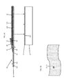
- FIG. 1A is a side view of a bonding preparation patch in accordance with embodiments
- FIG. 1B is a top down view of a portion of the bonding preparation patch of FIG. 1 ;
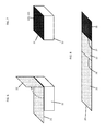
- FIG. 2 is a perspective view of an initial stage of a bonding preparation method in accordance with embodiments
- FIG. 3 is a perspective view of an intermediate stage of a bonding preparation method in accordance with embodiments
- FIG. 4 is a perspective view of an intermediate stage of a bonding preparation method in accordance with embodiments
- FIG. 5 is a perspective view of an intermediate stage of a bonding preparation method in accordance with embodiments.
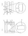
- FIG. 6 is a perspective view of an intermediate stage of a bonding preparation method in accordance with embodiments.
- FIG. 7 is a perspective view of a final stage of a bonding preparation method in accordance with embodiments.
- FIG. 8 is a perspective view of a portion of the bonding preparation patch of FIG. 1 in accordance with alternative embodiments
- FIG. 9 is a top down view of a resin barrier and strip material in accordance with embodiments.
- FIG. 10 is a side view of the resin barrier and strip material of FIG. 9 .
- a bonding preparation patch is provided and is formed of a strip of porous, woven material that is folded to form a flap with the non-flap portion laid generally flat against a resin surface. As a result, the resin soaks into, and partially through, the portion of the material laid flat against the resin. A barrier is provided to separate the flap and non-flap portions of the material which serves to prevent the resin from soaking through to the flap portion. The flap is then pressed flat and secured through the use of tape.
- the tape may be removed exposing the flap portion of the material.
- the non-flap portion of the material may be separated from the underlying resin treated surface.
- the strip With the strip removed, the area of contact between the material and the resin treated surface exhibits a matte surface owing to the surface characteristics of the material which has been imprinted upon the resin treated surface.
- Such a bonding preparation patch may be distributed at any place about a resin treated surface and left in place until the resin treated surface has been assembled into an airframe or other structure.
- a bonding preparation patch 10 is provided for application to, for example, a resin treated surface 11 of an airframe component 12 of an aircraft.
- the airframe component 12 may be any component of the aircraft (e.g., structural or otherwise).
- the patch 10 includes a strip 20 .
- the strip 20 has a first portion 21 that has first and second opposite sides 210 , 211 and a second portion 22 that also has first and second opposite sides 220 , 221 .
- the strip 20 may be initially planarized such that the respective first sides 210 and 220 are co-planar and the respective second sides 211 and 221 are also co-planar.
- the strip 20 is disposable on the resin treated surface 11 such that the second side 211 of the first portion 21 impinges on the resin treated surface 11 and the first side 210 faces away from the resin treated surface 11 .
- the strip 20 is formed of resin porous material, such as a woven fabric material 23 .
- This material 23 has a pattern that is defined as a negative of a desired pattern that is to be imprinted on the resin treated surface 11 (e.g., a matte finish so that the material 23 has to have a negative of a matte finish or a matrix of square or polygons so that the material 23 has to have a cross-linked, weave pattern). That is, once the strip 20 is disposed on the resin treated surface 11 , the resin 110 provided thereon in an uncured, liquid and sticky form seeps or leaks through the first portion 21 of the strip 20 from the second side 211 to the first side 210 . In doing so, the resin 110 assumes the negative (or imprinted or reverse) pattern of the material 23 pattern.
- the material 23 pattern and the chemistry of the resin and the material 23 can be variable for different applications and combinations.
- the strip 20 further includes a resin barrier 30 and a tape 40 and is foldable along fold 24 such that the respective first sides 210 and 220 of the first and second portions 21 and 22 face each other with the resin barrier 30 interposable between corresponding portions of the respective first sides 210 and 220 .
- the resin barrier 30 may be formed of fluorinated ethylene propylene (FEP) or another similar material such that the presence of the resin barrier 30 prevents the resin 110 that has seeped or leaked through the first portion 21 from seeping or leaking from the first side 210 of the first portion 21 to any part of the second portion 22 . Edges of the resin barrier 30 may be flush with corresponding edges of the strip 20 as shown in FIG. 4 however this is not necessary and, in some embodiments, the edges of the resin barrier 30 extend beyond the edges of the strip 20 or terminate short of the edges of the strip 20 .
- FEP fluorinated ethylene propylene
- the tape 40 secures the second portion 22 in the folded condition with the resin barrier 30 in place.
- the application of the tape 40 can also serve as the application of force necessary to cause the resin 110 to seep or leak through the first portion 21 of the strip 20 .
- the tape 40 may be formed of flouro peel tape or another similar material and includes at least one adhesive side 41 (see FIG. 1 ).
- This adhesive side 41 is securable relative to the first portion 21 and is disposable in contact with the second side 221 of the second portion 22 .
- the adhesive side 41 adhesively contacts the second side 221 of the second portion 22 , an exposed portion 31 of the resin barrier 30 and an exposed portion 25 of the first side 211 of the first portion 21 .
- the adhesive side 41 contacts with another laminate feature, such as a second layer of tape, which in turn contacts the first side of the first portion 21 .
- Edges of the tape 40 may be flush with corresponding edges of the strip 20 as shown in FIG. 5 however this is not necessary and, in some embodiments, the edges of the tape 40 extend beyond the edges of the strip 20 or terminate short of the edges of the strip 20 .
- the resin barrier 30 may be disposed proximate to or in an abutting condition with the fold 24 .
- the resin barrier 30 may occupy an entirety or at least a substantial entirety of the space defined between the respective first sides 210 and 220 .
- the resin barrier 30 is disposed to prevent all or substantially all of the resin 110 that has seeped or leaked through the first portion 21 from seeping or leaking from the first side 210 of the first portion 21 to any part of the second portion 22 .
- the resin 110 is cured.
- Such curing may be achieved by heat treatment, ultraviolet (UV) radiation treatment or another similar curing treatment.
- the resin 110 is cured and thus assumes the negative, reverse or imprinted pattern.
- the tape 40 is removed, the second portion 22 of the strip 20 is unfolded away from the resin barrier 30 and the resin barrier 30 is removed.
- the strip 20 is removed, pulled or lifted off of the resin treated surface 11 by a pulling force being applied to the second portion 22 to thus reveal the cured resin 110 and its imprinted matte finish pattern 111 .
- This imprinted matte finish pattern 111 provides for a surface that is prepared for bonding and needs no further curing or machining in order to enhance the bonding ability of whatever glue or bonding material may be used to subsequently attach clips or other holding devices thereto.
- the material 23 of the strip 20 is selective to have a sufficient tensile strength to resist tearing of the strip 20 upon separation of the strip 20 from the resin treated surface 11 as a result of the pulling force being applied to the second portion 22 .
- the resin barrier 30 may be provided as a part or component of the strip 20 .
- the strip 20 may include the first portion 21 , the second portion 22 and a third portion 26 , which are arranged with the second portion 22 being sandwiched between the first and third portions 21 and 26 .
- the third portion 26 is coated with FEP to provide for the resin barrier and the strip 20 is foldable twice along fold 24 and secondary fold 27 such that the third portion 26 ends up disposed between the first and second portions 21 and 22 .
- the material 23 of the strip 20 is configured to provide the resin treated surface 11 , once cured, with a characteristic bondability value of at least 10 inch-pounds/inch of width or, more particularly, at least 13.6 inch-pounds/inch of width. This can be achieved by the formation/imprinting of the desired pattern on the resin treated surface 11 . It may also be achieved by an additional mechanical and/or chemical embossment or modification of the resin treated surface 11 by the individual lines or threads 231 of the material 23 .
- the threads 231 may be disposed with a surface roughness 232 that leaves a corresponding roughness in the sides 233 of the surface features of the resin treated surface 11 as the strip 20 is pulled off of the resin treated surface 11 .
- the threads 231 may be coated with a certain chemical that mixes with the resin of the resin treated surface 11 during the above-described processing so that the resulting stickiness or bondability of the resin composite is increased.
- the threads 231 may be made of a certain chemical that mixes with the resin of the resin treated surface 11 during the above-described processing so that the resulting stickiness or bondability of the resin composite is increased.
- a surface 300 of the resin barrier 30 contacts the resin that seeps or leaks through the first portion 21 of the strip 20 from the second side 211 to the first side 210 .
- This surface 300 may be configured in a similar manner as the individual threads 231 of the material 23 to provide for mechanical or chemical embossments or modifications of the resin treated surface 11 . That is, the surface 300 may be disposed with a surface roughness 301 that leaves a corresponding roughness in the upper surface 302 of the surface features of the resin treated surface 11 as the strip 20 is pulled off of the resin treated surface 11 .
- the surface 300 may be coated with a certain chemical that mixes with the resin of the resin treated surface 11 during the above-described processing so that the resulting stickiness or bondability of the resin composite is increased.
- the surface 300 may be made of a certain chemical that mixes with the resin of the resin treated surface 11 during the above-described processing so that the resulting stickiness or bondability of the resin composite is increased.
- resin barrier 30 may not have sufficient tensile strength to resist tearing of the strip 20 upon separation of the strip 20 from the resin treated surface 11 as a result of the pulling force being applied to the second portion 22 . That strength is provided by the strip 20 .
- the entire strip 20 were coated with a resin barrier and then folded once (along 24 , for instance), the portion of the strip 20 that was remote from the resin would be easily separated (since there is resin barrier in contact with resin barrier) and act as a pull-tab.
- Such a pull tab would be of sufficient tensile strength to resist the tearing of the strip 20 upon separation of the strip 20 from the resin treated surface 11 as a result of the pulling force being applied to the second portion 22 .
- the strip 20 , the resin barrier 30 and the tap 40 can all be printed in three dimensions (3D printed). That is, digital representations of these features can be provided in a format that is readable by a given 3D printer. Thus, when the digital representation are input into and acted upon by the 3D printer, the digital representations are read by the 3D printer and cause the 3D printer to 3D print the strip 20 , the resin barrier 30 and the tape 40 .
Landscapes
- Engineering & Computer Science (AREA)
- Mechanical Engineering (AREA)
- Chemical & Material Sciences (AREA)
- Materials Engineering (AREA)
- Manufacturing & Machinery (AREA)
- Aviation & Aerospace Engineering (AREA)
- Physics & Mathematics (AREA)
- Optics & Photonics (AREA)
- Laminated Bodies (AREA)
- Lining Or Joining Of Plastics Or The Like (AREA)
Abstract
Description
Claims (12)
Priority Applications (1)
| Application Number | Priority Date | Filing Date | Title |
|---|---|---|---|
| US15/557,183 US10471663B2 (en) | 2015-03-16 | 2016-03-10 | Bonding preparation patch |
Applications Claiming Priority (3)
| Application Number | Priority Date | Filing Date | Title |
|---|---|---|---|
| US201562133649P | 2015-03-16 | 2015-03-16 | |
| US15/557,183 US10471663B2 (en) | 2015-03-16 | 2016-03-10 | Bonding preparation patch |
| PCT/US2016/021783 WO2016149036A1 (en) | 2015-03-16 | 2016-03-10 | Bonding preparation patch |
Publications (2)
| Publication Number | Publication Date |
|---|---|
| US20180043624A1 US20180043624A1 (en) | 2018-02-15 |
| US10471663B2 true US10471663B2 (en) | 2019-11-12 |
Family
ID=56919331
Family Applications (1)
| Application Number | Title | Priority Date | Filing Date |
|---|---|---|---|
| US15/557,183 Active 2036-06-18 US10471663B2 (en) | 2015-03-16 | 2016-03-10 | Bonding preparation patch |
Country Status (2)
| Country | Link |
|---|---|
| US (1) | US10471663B2 (en) |
| WO (1) | WO2016149036A1 (en) |
Citations (7)
| Publication number | Priority date | Publication date | Assignee | Title |
|---|---|---|---|---|
| US2569954A (en) | 1946-06-27 | 1951-10-02 | Us Rubber Co | Adhesive for bonding plasticized polyvinyl halide-containing resin surfaces and method of bonding such surfaces |
| US4783362A (en) | 1987-09-30 | 1988-11-08 | Stern & Stern Industries, Inc. | Peel ply material |
| WO1998022069A1 (en) | 1996-11-22 | 1998-05-28 | Minnesota Mining And Manufacturing Company | Laminate tape |
| US6827893B2 (en) * | 2000-03-14 | 2004-12-07 | Velcro Industries B.V. | Folded fastener products |
| US20130129957A1 (en) * | 2011-12-30 | 2013-05-23 | Cytec Technology Corp. | Peel Ply, Method of Surface Preparation and Bonding Composite Structures Using the Same |
| US20130280488A1 (en) | 2012-04-23 | 2013-10-24 | Brian D. Flinn | Bond ply for adhesive bonding of composites and associated systems and methods |
| US20150056433A1 (en) | 2013-08-22 | 2015-02-26 | Cytec Industries Inc. | Bonding of composite materials |
-
2016
- 2016-03-10 WO PCT/US2016/021783 patent/WO2016149036A1/en not_active Ceased
- 2016-03-10 US US15/557,183 patent/US10471663B2/en active Active
Patent Citations (8)
| Publication number | Priority date | Publication date | Assignee | Title |
|---|---|---|---|---|
| US2569954A (en) | 1946-06-27 | 1951-10-02 | Us Rubber Co | Adhesive for bonding plasticized polyvinyl halide-containing resin surfaces and method of bonding such surfaces |
| US4783362A (en) | 1987-09-30 | 1988-11-08 | Stern & Stern Industries, Inc. | Peel ply material |
| WO1998022069A1 (en) | 1996-11-22 | 1998-05-28 | Minnesota Mining And Manufacturing Company | Laminate tape |
| US6827893B2 (en) * | 2000-03-14 | 2004-12-07 | Velcro Industries B.V. | Folded fastener products |
| US20130129957A1 (en) * | 2011-12-30 | 2013-05-23 | Cytec Technology Corp. | Peel Ply, Method of Surface Preparation and Bonding Composite Structures Using the Same |
| US9473459B2 (en) * | 2011-12-30 | 2016-10-18 | Cytec Technology Corp. | Peel ply, method of surface preparation and bonding composite structures using the same |
| US20130280488A1 (en) | 2012-04-23 | 2013-10-24 | Brian D. Flinn | Bond ply for adhesive bonding of composites and associated systems and methods |
| US20150056433A1 (en) | 2013-08-22 | 2015-02-26 | Cytec Industries Inc. | Bonding of composite materials |
Non-Patent Citations (1)
| Title |
|---|
| PCT/US2016/021783 ISR/WO, dated Jun. 2, 2016, 16 pages. |
Also Published As
| Publication number | Publication date |
|---|---|
| WO2016149036A1 (en) | 2016-09-22 |
| US20180043624A1 (en) | 2018-02-15 |
Similar Documents
| Publication | Publication Date | Title |
|---|---|---|
| US9661743B1 (en) | Flexible circuit board and method of fabricating | |
| JP7586973B2 (en) | Method and apparatus for forming ventilation paths in pressure sensitive adhesives for laminate stacks - Patents.com | |
| KR20110086510A (en) | Laminating method of prepreg, manufacturing method of printed wiring board and roll of prepreg | |
| CN104220688A (en) | Hinge of composite material and method for its production | |
| CN101253045A (en) | Method of laminating adherends | |
| JP6204093B2 (en) | Method for manufacturing reinforcing structure | |
| KR20130090115A (en) | Method for forming solder resist and print circuit board with the same solder resist | |
| DK1286833T4 (en) | Process for producing multilayer document cards and document cards made therewith | |
| US10471663B2 (en) | Bonding preparation patch | |
| KR20150104085A (en) | Method of fabricating a curved composite structure using composite prepreg tape | |
| US4780159A (en) | Method of laminating multi-layer noise suppression structures | |
| JPH10296864A (en) | Device and method for molding composite material | |
| JP2007521164A (en) | Laminate with filler layer | |
| WO2022015195A1 (en) | Boat hull (device and method of manufacture) | |
| RU2412815C2 (en) | Method of repairing composite structure outer envelopment | |
| JP2004306455A (en) | Method for manufacturing composite honeycomb sandwich structure | |
| JP2010105207A (en) | Screen printing plate and method for manufacturing the same | |
| JP3366458B2 (en) | Manufacturing method of printed wiring board | |
| WO2020004226A1 (en) | Aircraft interior member, method of manufacturing same, and method of replacing same | |
| DE102010054974A1 (en) | Printed circuit board and method for the production of printed circuit boards | |
| EP0901901A3 (en) | Method and apparatus for laminating flexible webs | |
| JP2014123755A (en) | Protective film for fpc, resin conductor foil laminate with protective film for fpc, and method of manufacturing flexible printed wiring board using it | |
| KR20210035932A (en) | FFC with PCT film and Method for making the FFC | |
| JP7256561B2 (en) | Card and its manufacturing method | |
| JP5179326B2 (en) | Flex rigid printed circuit board |
Legal Events
| Date | Code | Title | Description |
|---|---|---|---|
| AS | Assignment |
Owner name: SIKORSKY AIRCRAFT CORPORATION, CONNECTICUT Free format text: ASSIGNMENT OF ASSIGNORS INTEREST;ASSIGNOR:TRUDEAU, ALLEN E.;REEL/FRAME:043542/0955 Effective date: 20160215 |
|
| FEPP | Fee payment procedure |
Free format text: ENTITY STATUS SET TO UNDISCOUNTED (ORIGINAL EVENT CODE: BIG.); ENTITY STATUS OF PATENT OWNER: LARGE ENTITY |
|
| STPP | Information on status: patent application and granting procedure in general |
Free format text: NON FINAL ACTION MAILED |
|
| STPP | Information on status: patent application and granting procedure in general |
Free format text: RESPONSE TO NON-FINAL OFFICE ACTION ENTERED AND FORWARDED TO EXAMINER |
|
| STPP | Information on status: patent application and granting procedure in general |
Free format text: NOTICE OF ALLOWANCE MAILED -- APPLICATION RECEIVED IN OFFICE OF PUBLICATIONS |
|
| STPP | Information on status: patent application and granting procedure in general |
Free format text: PUBLICATIONS -- ISSUE FEE PAYMENT RECEIVED |
|
| STCF | Information on status: patent grant |
Free format text: PATENTED CASE |
|
| MAFP | Maintenance fee payment |
Free format text: PAYMENT OF MAINTENANCE FEE, 4TH YEAR, LARGE ENTITY (ORIGINAL EVENT CODE: M1551); ENTITY STATUS OF PATENT OWNER: LARGE ENTITY Year of fee payment: 4 |