US1043564A - Form for cases, boxes, &c. - Google Patents
Form for cases, boxes, &c. Download PDFInfo
- Publication number
- US1043564A US1043564A US68527212A US1912685272A US1043564A US 1043564 A US1043564 A US 1043564A US 68527212 A US68527212 A US 68527212A US 1912685272 A US1912685272 A US 1912685272A US 1043564 A US1043564 A US 1043564A
- Authority
- US
- United States
- Prior art keywords
- sides
- bars
- base
- hinged
- receptacle
- Prior art date
- Legal status (The legal status is an assumption and is not a legal conclusion. Google has not performed a legal analysis and makes no representation as to the accuracy of the status listed.)
- Expired - Lifetime
Links
Images
Classifications
-
- B—PERFORMING OPERATIONS; TRANSPORTING
- B25—HAND TOOLS; PORTABLE POWER-DRIVEN TOOLS; MANIPULATORS
- B25B—TOOLS OR BENCH DEVICES NOT OTHERWISE PROVIDED FOR, FOR FASTENING, CONNECTING, DISENGAGING, OR HOLDING
- B25B5/00—Clamps
- B25B5/14—Clamps for work of special profile
- B25B5/142—Clamps for work of special profile for windows and frames
Definitions
- the invention relates to improvements in forms for cases, boxes, etc.
- the object of the present invention is to improve the construction of forms for cases, boxes, and analogous receptacles, and to provide a simple, eiicient and inexpensive construction, adapted to hold the sides, ends, bottoms and partitionsof such receptacles in assembled relation while they are being nailed together, and equipped with means for enabling the nails to be accurately driven at the proper points, so that egg cases and other receptacles shipped in a knockeddown condition may be quickly and accurately set up without liability of any mistake in nailing the parts together.
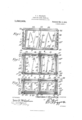
- z- Figure 1 is a side elevation of a form, constructed in accordance with this invention, the parts of an egg case being in position for nailing.
- Fig. 2 is a central longitudinal sectional view of the same.
- Fig. 3 is a horizontal sectional view.
- Fig. 4 is a transverse sectional ⁇ view on the line 4 4 of Fig. 2.
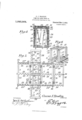
- Eig. 5 is a plan view, the hinged sides, ends and top of the" form being swung outwardly and downwardly to a horizontal position.
- Eig. 6 is a detail perspective view of a portion of the form, illustrating one of lthe interior supporting frames.
- the form comprises in its construction a horizontal bottom or base 1 upon which is mounted fixed spaced frames or supports 2, between which is placed a central partition 3 and against which the sides 4 and ends 5 of an egg crate are clamped by hinged sides and ends G and 7 of the form.
- the base or bottom is preferably composed of longitudinal side bars S and intermediate and end transverse connecting bars 9 and 10, suitably secured to the side bars, the intermediate transverse connecting bar 9 preferably having its ends 11 dove-tailed into the side bars 8, while the terminals of the side and end bars 8 and 1() are recessed and overlapped, but the bars of the base may be secured together in any desired manner, as will be readily understood.
- Each of the 'supporting frames 2 is composed of vertical corner posts 12, connected at their upper and lower ends by top and bottom transverse bars 13 and 14, whichare connected by top and bottom longitudinal bars 15 and 16, upper and lower transverse braces 17 and 18 being preferably interposed between the longitudinal bars 15 and 16 and secured to the same at the centers thereof.
- the top and bottom longitudinal bars 15 and 16 are inwardly off-set from the planes of the outer faces of the corner posts, but the supporting frames may be'constructed in any desired manner, and their number may be varied t0 enable one or more partitions to be support ed in position for nailing, and when a box is to be constructed without a partition, only a single supporting frame is necessary.
- the frames 2 are adapted to support the crate bottom 19, which is held in place by the top 20 of the form-
- the sides 6, which consist of open frames, are connected at their lower edges to the bottom orbase 1 by hinges 21, and each side is composed of top and bottom'longitudinal bars 22 and 23, and intermediate and end vertical connecting bars 24 and 25, which have their upper and lower terminals gained or mortised in the longitudinal bars to arrange the vertical bars 24 and 25 in flush relation with the outer faces of the top and bottom longitudinal bars.
- the said bars may, however, be secured together in any other desired manner, and .the hinged sides of the form extend above the tops of the supporting frames a sufficient distance to provide the necessary space for the bottom of the case, which is assembled in the form in an inverted position.
- the ends 7, which also consist of open frames, are connected at their lower ends with the bottom or base 1 by hinges 26, and are composed of spaced vertical bars 27 and top and bottom connecting bars 2S and 29, having their ends recessed, overlapped and secured together, the outer faces of the vertical side or corner bars 27 being arranged in flush relation with the outer faces of the top and bottom connecting bars 23 and 29.
- the hinged ends of the form terminate at and in flush rela-- tion with the end edges of the bottom or base, and the hinged ends of the form eX- tend laterally to the outer faces of the hinged sides, the side edges of the ends being in flush relation with the outer faces of the hinged sides.
- the top 20 which like the sides and ends consists of an open frame, is connected with one of the sides at the upper edge thereof by hinges 30, and it is composed of longitudinal side bars 31 and 32 and intermediate and end transverse connecting bars 33 and 34, secured at their terminals to the side bars and having their outer faces arranged iniiush relation with the outer faces of the side bars, the connecting portions of the bars of the hinged top being recessed and overlapped.
- the form is preferably constructed of wood, it may be made of met-al or a combination of wood and metal, wood being preferred in order to render the form light and enable the same to be easily handled.
- the form is designed for enabling the parts of an egg case, which are received in a knocked-down condition, to be readily assembled and held for nailing, and in assembling the parts of the egg case, the central partition is fitted between the spaced supporting frames, and the sides and ends are placed upon the hinged sides and ends 6 and 7 which are preferably arranged in a hori- Zontal position for this purpose.
- the sides and ends are then swung upwardly to a vertical position to close the form and clamp the sides and ends of the egg case against the Xed supporting frames.
- the bottom of the egg case is then placed upon the supporting frames and the hinged top of the form is closed over the egg case bottom.
- the terminals of the sides of the egg case are arranged against the side edges of the ends of the egg case, and the bottom of the egg case overlaps or extends over the edges of both the sides and ends of the said egg case.
- the vertical end bars 25 of the hinged sides 6 are provided at their inner faces with vertical strips 25a, arranged in flush relation with the outer vertical edges of the bars 25 and adapted to't against the outer faces of the egg case ends and terminating short of the horizontal edges thereof to provide spaces for top and bottom cleats 5a when it is desired to equip the egg case with the same.
- rlhe hinged ends 7 directly engage the cleats 5a and thereby clamp the egg crate ends against the fixed supports 2.
- One or bot-h of the cleats 5'"L may be omitted, and with such a construction it will be unnecessary to terminate the vertical strips 25 short of the upper and lower edges of the sides 6 of the form.
- the parts of the form are secured in their closed posit-ion by side hooks 35 and a top hook 36.
- the side hooks 35 which are L- shaped, are arranged at the upper corners of the hinged sides 6 of the form, and they receive or brace the upper corners of the hinged ends 7 of the form, and the top hook 36 is centrally arranged at the free edge of the hinged top 20 and engages the outer face of the adjacent side 6, but any other form of catch may be employed for securing the hinged members of the form together.
- the terminals of the egg case sides are nailed to the vertical edges of the egg case ends, and the vertical bars 25 are provided at intervals with inwardly tapered recesses 37, extending inwardly beyond the vertical strips 25al and adapted to expose portions of the egg crate sides to enable nails to be driven into the same, and the vertical bars of the hinged ends 7 are provided at their outer edges with inwardly tapered recesses 38, coinciding with the recesses 37 and providing ample space to permit the nails to be driven into the sides and ends of the egg case with an ordinary hammer.
- the intermediate vertical bars 24 of the sides 6 are provided at intervals with recesses 39, arranged in the plane of the partition 3 for enabling the egg crate sides to be nailed to the ⁇ vertical edges of the said partition.
- the hinged top 2O of the form is provided in its transverse end bars with recesses l0 and in its intermediate transverse connecting bar 33 with recesses 4l.
- the recesses 4:0 and 4l which are similar to those heretofore described, are arranged at intervals and permit the bottom of the egg case to be nailed to the contiguous horizontal edges of the ends 5 and the partition 3 of the egg case.
- the recesses form guides for nailing the assembled parts of the case together, and the bars in which the recesses are formed enable pressure to be applied around the parts being nailed, so that the assembled parts of the receptacle may be vertically held While being nailed.
- the form is opened and inverted to permit the completed egg case to drop out of the form.
- a form of the class described including a horizontal base, fixed support-ing means mounted on the base and adapted to support the bottom of a receptacle and with the sides and ends thereof fitted against it, side and end clamping members each hinged at its lower edge to the base and adapted to'swing upwardly to a vertical position for clamping the sides and ends of the receptacle against the said supporting means, and a horizontal top clamping member hinged to the upper edge of one of the side members, and means for securing the members in their closed position in engagement with the sides, ends and bottom of the receptacle.
- a form of the class described including a base, fixed supporting frames mounted on the base and spaced apart to receive a vertical partition between them and adapted to support the top of a receptacle and having the sides and ends of the same fitted against them, side and end members hinged to the base and arranged to c'lamp'the sides and ends of the receptacle against the supporting frames, and a top member hinged toene of the side members for clamping the bottom of the receptacle upon the supporting frames.
- a form of the class described including a rectangular base, fixed supporting means mounted upon the base and adapted to have the sides and ends Aof a receptacle ⁇ fitted against it, rectangular side and end members hinged at their lower edges to the base ⁇ and arranged to swing upwardly to a vertical.
- a form of the class descrlbed including a base, iixed supporting frames mountedon the base and adapted to support the bot-tom of a receptacle and have the sidesl and ends thereof fitted against them, saidv supportingl frames being spaced apart to receive a par,- tition between them to support the same in a vertical position in contact with the sides and bottom of the receptacle, side and end members hinged at their lower edges to the base and arranged to swing upwardly to a vertical position to clamp the sides and ends of the receptacle against the supporting frames, and a horizontal top clamping member hinged to one of the side members and arranged to clamp the ⁇ bottom of the recepvtacle upon the supporting frames and against the said partition.
- a form of the class described including a base, fixed supporting means mounted on the base and adapted to receive the sides and ends of a receptacle, and rectangular side and end members hinged at their lower edges to the base and arranged to swing upwardly to a vertical position to clamp the said sides and ends against the supporting Vmeans and consisting of open rectangular frames provided at the corners of the receptacle with vertical abutting bars having coincident recesses arranged at intervals to permit the sides and ends to be nailed together.
- a form of the class described including a base, fixed supporting means mounted on the base and adapted to receive the sides and ends of a receptacle, rectangular side and end members hinged at their lower edges to the base and arranged to swing upwardly to a vertical position to clamp the said sides and ends against the supporting means and consisting of open rectangular frames provided at the corners of the receptacle with verticalV abutting bars having coincident recesses arranged at intervals topermit the sides and ends to be nailed together, and vertical strips secured to the inner faces of the side members and terminating short of the upper and lower edges thereof and arranged to engage the ends of the receptacle between top and bottom cleats thereof.
- a form of the class described including a base, fixed supporting frames mounted on the base and spaced apart to support a partition in a vertical position, side members hinged vto the base for clamping the sides of a receptacle against the same, a top memberhinged to one of the side members for clamping the bottom of the receptacle upon the ⁇ fixed supports, said side and top members having bars arranged in the plane of the partition and provided at intervals with. recesses to permit the kbottom and sides of the receptacle to be nailed to the partition.
- a form of the class described including a base, fixed supports mounted on the base ⁇ and spaced apart to permit a vertical partition to Vbey arranged between them, side membershinged to the base for clamping the sides of a receptacle against the supports vand consistingof open frames provided intermediate of their ends with vertical bars having recesses arranged in the plane of the partitionto enable the sides of the receptacle to be nailed to the same, a top member hinged to one of the side members for clamping the bottom of the receptacle upon the supports and consisting of an open frame having an intermediate transverse ⁇ connecting bar provided at intervals with' recesses arranged in the plane of the partition ⁇ for enabling the bottom of the box to be nailed to the same.
- a form of the class described including a horizontal base, fixed supporting means mounted on the base and adapted to support the bottom of a receptacle and to receive the sides and ends thereof, rectangular side and end members hinged at their lower edges to the base and arranged to swing upwardly' to a vertical position to clamp the sides and ends of the receptacle against the supporting means and provided With vertical corner bars having coincident recesses arranged at intervals, and a horizontal rectangular top clamping member hinged to one of the side members and arranged to clamp the bottom of the receptacle and provided With end bars having recesses arranged at intervals.
- a form of the class described including a base, fixed supports spaced apart to permit a partit-ion to be placed between them and adapted to support the bottom of a receptacle and to receive the sides and ends thereof, end members hinged to the base andprovided in their vertical edges with recesses, side members hinged to the base and consisting' of open frames provided at their ends With recesses coinciding With the recesses of the end members, said side members being provided with intermediate vertical bars having recesses arranged in the plane of the partition, a top member consisting of an open frame provided at its ends With recesses and having an intermediate transverse bar provided With recesses arranged in the plane of the partition.
- a form of the class described comprising a base, spacedl supports iXed to the base and each composed of corner posts, top and bottom transverse connecting bars and spaced longitudinal connecting bars, side and end members hinged to the base for clamping the sides and ends of a receptacle against the said supports, and a top member hinged to one of the said members for clamping the bottom of the receptacle upon the supports.
Landscapes
- Engineering & Computer Science (AREA)
- Mechanical Engineering (AREA)
- Packaging Of Annular Or Rod-Shaped Articles, Wearing Apparel, Cassettes, Or The Like (AREA)
Description
C. J. BRADLEY. FORM POR GASES, BOXES, dw. APPLICATION FILED MAR. 21, 1912. 1,043,564 Y Patented Nov. 5, 1912.
2 SHEETS-SHEET l.
'MlllllllllllllllllllllllllilllllImIlIIl- 2 I'' E sa l l x YI Il\\ l" lllllllgllll'Il"IlIIIIIIIIIIIIIIIIIIIIII ,mi
IIIIIIIIIIIIIIIIIIIIIIIIIIIIIIIIIIIl Z9 mm1- 5 5 .9 03725 .37 Z5 4, 2% Z3 Z5 38 i j f 39 "4 ZZ. r, j Z5 Hf M25 l WMV@ j. f
5 'T2414 4,32.' 129, 1512,* f 25d, Z5 j l Z5 Z7 f7 5 37 WITNEssEs Ulf/ZCJBVQCZLy/*NVENTOR ATTORN EY APH c0..wAsHINGroN D c ,o. J. BRADLEY. EoEM EOE GASES, BOXES, am. APPLICATION FILED MAR. 21, 1912.
Patented Nov. 5, 1912.
2 SHEETS-SHEET 2.
NTOR
Gla/@1266 Jmagg/ WITNESSES ATTORNEY UNITED STATES I PATENT OFFICE.
CLARENCE JEWELL BRADLEY, 0F BOWLING GREEN, MISSOURI, ASSIGNOR OF ONE- FOURTH TO GEORGE G. OGDEN AND ONE-FOURTH T0 WILLIAIVI S. WILI-IOIT, BOTH OE ASHLEY, MISSOURI.
FORM non casus, BOXES, ac.
Specification of Letters. Patent.
Patented Nov. 5, 1912.
To all whom t may concern;
Be it known that I, CLARENCE J. BRADLEY, a citizen of the United States, residing at Bowling Green, in the county of Pike and State of Missouri, have invented a new and useful Form for Cases, Boxes, &c., of which the following is a specification.
The invention relates to improvements in forms for cases, boxes, etc.
The object of the present invention is to improve the construction of forms for cases, boxes, and analogous receptacles, and to provide a simple, eiicient and inexpensive construction, adapted to hold the sides, ends, bottoms and partitionsof such receptacles in assembled relation while they are being nailed together, and equipped with means for enabling the nails to be accurately driven at the proper points, so that egg cases and other receptacles shipped in a knockeddown condition may be quickly and accurately set up without liability of any mistake in nailing the parts together.
`With these and other objects in view, the invention consists in the construction and novel combination of parts hereinafter fully described, illustrated in the accompanying drawings, and pointed out in the claims hereto appended; it being understood that various changes in the form, proportion, size and minor details of construction, within the scope of the claims, may be resorted to without departing from the spirit or sacrificing any of the advantages of the'invention.
In the drawings z-Figure 1 is a side elevation of a form, constructed in accordance with this invention, the parts of an egg case being in position for nailing. Fig. 2 is a central longitudinal sectional view of the same. Fig. 3 is a horizontal sectional view. Fig. 4 is a transverse sectional` view on the line 4 4 of Fig. 2. Eig. 5 is a plan view, the hinged sides, ends and top of the" form being swung outwardly and downwardly to a horizontal position. Eig. 6 is a detail perspective view of a portion of the form, illustrating one of lthe interior supporting frames.
Like numerals of reference designate cor responding parts in all the figures of the drawings.
In the accompanying drawings in which is illustrated the preferred embodiment of the invention, the form comprises in its construction a horizontal bottom or base 1 upon which is mounted fixed spaced frames or supports 2, between which is placed a central partition 3 and against which the sides 4 and ends 5 of an egg crate are clamped by hinged sides and ends G and 7 of the form. The base or bottom is preferably composed of longitudinal side bars S and intermediate and end transverse connecting bars 9 and 10, suitably secured to the side bars, the intermediate transverse connecting bar 9 preferably having its ends 11 dove-tailed into the side bars 8, while the terminals of the side and end bars 8 and 1() are recessed and overlapped, but the bars of the base may be secured together in any desired manner, as will be readily understood. Each of the 'supporting frames 2 is composed of vertical corner posts 12, connected at their upper and lower ends by top and bottom transverse bars 13 and 14, whichare connected by top and bottom longitudinal bars 15 and 16, upper and lower transverse braces 17 and 18 being preferably interposed between the longitudinal bars 15 and 16 and secured to the same at the centers thereof. The top and bottom longitudinal bars 15 and 16 are inwardly off-set from the planes of the outer faces of the corner posts, but the supporting frames may be'constructed in any desired manner, and their number may be varied t0 enable one or more partitions to be support ed in position for nailing, and when a box is to be constructed without a partition, only a single supporting frame is necessary. The frames 2 are adapted to support the crate bottom 19, which is held in place by the top 20 of the form- The sides 6, which consist of open frames, are connected at their lower edges to the bottom orbase 1 by hinges 21, and each side is composed of top and bottom'longitudinal bars 22 and 23, and intermediate and end vertical connecting bars 24 and 25, which have their upper and lower terminals gained or mortised in the longitudinal bars to arrange the vertical bars 24 and 25 in flush relation with the outer faces of the top and bottom longitudinal bars. The said bars may, however, be secured together in any other desired manner, and .the hinged sides of the form extend above the tops of the supporting frames a sufficient distance to provide the necessary space for the bottom of the case, which is assembled in the form in an inverted position. The ends 7, which also consist of open frames, are connected at their lower ends with the bottom or base 1 by hinges 26, and are composed of spaced vertical bars 27 and top and bottom connecting bars 2S and 29, having their ends recessed, overlapped and secured together, the outer faces of the vertical side or corner bars 27 being arranged in flush relation with the outer faces of the top and bottom connecting bars 23 and 29. The hinged ends of the form terminate at and in flush rela-- tion with the end edges of the bottom or base, and the hinged ends of the form eX- tend laterally to the outer faces of the hinged sides, the side edges of the ends being in flush relation with the outer faces of the hinged sides.
The top 20, which like the sides and ends consists of an open frame, is connected with one of the sides at the upper edge thereof by hinges 30, and it is composed of longitudinal side bars 31 and 32 and intermediate and end transverse connecting bars 33 and 34, secured at their terminals to the side bars and having their outer faces arranged iniiush relation with the outer faces of the side bars, the connecting portions of the bars of the hinged top being recessed and overlapped.
lVhile the form is preferably constructed of wood, it may be made of met-al or a combination of wood and metal, wood being preferred in order to render the form light and enable the same to be easily handled.
The form is designed for enabling the parts of an egg case, which are received in a knocked-down condition, to be readily assembled and held for nailing, and in assembling the parts of the egg case, the central partition is fitted between the spaced supporting frames, and the sides and ends are placed upon the hinged sides and ends 6 and 7 which are preferably arranged in a hori- Zontal position for this purpose. The sides and ends are then swung upwardly to a vertical position to close the form and clamp the sides and ends of the egg case against the Xed supporting frames. The bottom of the egg case is then placed upon the supporting frames and the hinged top of the form is closed over the egg case bottom. The terminals of the sides of the egg case are arranged against the side edges of the ends of the egg case, and the bottom of the egg case overlaps or extends over the edges of both the sides and ends of the said egg case.
The vertical end bars 25 of the hinged sides 6 are provided at their inner faces with vertical strips 25a, arranged in flush relation with the outer vertical edges of the bars 25 and adapted to't against the outer faces of the egg case ends and terminating short of the horizontal edges thereof to provide spaces for top and bottom cleats 5a when it is desired to equip the egg case with the same. rlhe hinged ends 7 directly engage the cleats 5a and thereby clamp the egg crate ends against the fixed supports 2. One or bot-h of the cleats 5'"L may be omitted, and with such a construction it will be unnecessary to terminate the vertical strips 25 short of the upper and lower edges of the sides 6 of the form.
The parts of the form are secured in their closed posit-ion by side hooks 35 and a top hook 36. The side hooks 35, which are L- shaped, are arranged at the upper corners of the hinged sides 6 of the form, and they receive or brace the upper corners of the hinged ends 7 of the form, and the top hook 36 is centrally arranged at the free edge of the hinged top 20 and engages the outer face of the adjacent side 6, but any other form of catch may be employed for securing the hinged members of the form together.
The terminals of the egg case sides are nailed to the vertical edges of the egg case ends, and the vertical bars 25 are provided at intervals with inwardly tapered recesses 37, extending inwardly beyond the vertical strips 25al and adapted to expose portions of the egg crate sides to enable nails to be driven into the same, and the vertical bars of the hinged ends 7 are provided at their outer edges with inwardly tapered recesses 38, coinciding with the recesses 37 and providing ample space to permit the nails to be driven into the sides and ends of the egg case with an ordinary hammer. The intermediate vertical bars 24 of the sides 6 are provided at intervals with recesses 39, arranged in the plane of the partition 3 for enabling the egg crate sides to be nailed to the `vertical edges of the said partition. The hinged top 2O of the form is provided in its transverse end bars with recesses l0 and in its intermediate transverse connecting bar 33 with recesses 4l. The recesses 4:0 and 4l, which are similar to those heretofore described, are arranged at intervals and permit the bottom of the egg case to be nailed to the contiguous horizontal edges of the ends 5 and the partition 3 of the egg case. The recesses form guides for nailing the assembled parts of the case together, and the bars in which the recesses are formed enable pressure to be applied around the parts being nailed, so that the assembled parts of the receptacle may be vertically held While being nailed. After the parts have been nailed together, the form is opened and inverted to permit the completed egg case to drop out of the form.
What is claimed is 1. A form of the class described including a horizontal base, fixed support-ing means mounted on the base and adapted to support the bottom of a receptacle and with the sides and ends thereof fitted against it, side and end clamping members each hinged at its lower edge to the base and adapted to'swing upwardly to a vertical position for clamping the sides and ends of the receptacle against the said supporting means, and a horizontal top clamping member hinged to the upper edge of one of the side members, and means for securing the members in their closed position in engagement with the sides, ends and bottom of the receptacle.
2. A form of the class described including a base, fixed supporting frames mounted on the base and spaced apart to receive a vertical partition between them and adapted to support the top of a receptacle and having the sides and ends of the same fitted against them, side and end members hinged to the base and arranged to c'lamp'the sides and ends of the receptacle against the supporting frames, and a top member hinged toene of the side members for clamping the bottom of the receptacle upon the supporting frames.
3. A form of the class described including a rectangular base, fixed supporting means mounted upon the base and adapted to have the sides and ends Aof a receptacle `fitted against it, rectangular side and end members hinged at their lower edges to the base` and arranged to swing upwardly to a vertical.
position to clamp the sides and endsv of the receptacle against the supporting means and provided with vertical bars arranged at the corners of the receptacle and provided at intervals with recesses to enable the sides and ends of the receptacle to be nailed together while within the form.
1i. A form of the class descrlbedincluding a base, iixed supporting frames mountedon the base and adapted to support the bot-tom of a receptacle and have the sidesl and ends thereof fitted against them, saidv supportingl frames being spaced apart to receive a par,- tition between them to support the same in a vertical position in contact with the sides and bottom of the receptacle, side and end members hinged at their lower edges to the base and arranged to swing upwardly to a vertical position to clamp the sides and ends of the receptacle against the supporting frames, and a horizontal top clamping member hinged to one of the side members and arranged to clamp the `bottom of the recepvtacle upon the supporting frames and against the said partition.
5. A form of the class described including a base, fixed supporting means mounted on the base and adapted to receive the sides and ends of a receptacle, and rectangular side and end members hinged at their lower edges to the base and arranged to swing upwardly to a vertical position to clamp the said sides and ends against the supporting Vmeans and consisting of open rectangular frames provided at the corners of the receptacle with vertical abutting bars having coincident recesses arranged at intervals to permit the sides and ends to be nailed together.V
6. A form of the class described including a base, fixed supporting means mounted on the base and adapted to receive the sides and ends of a receptacle, rectangular side and end members hinged at their lower edges to the base and arranged to swing upwardly to a vertical position to clamp the said sides and ends against the supporting means and consisting of open rectangular frames provided at the corners of the receptacle with verticalV abutting bars having coincident recesses arranged at intervals topermit the sides and ends to be nailed together, and vertical strips secured to the inner faces of the side members and terminating short of the upper and lower edges thereof and arranged to engage the ends of the receptacle between top and bottom cleats thereof.
7. A form of the class described including a base, fixed supporting frames mounted on the base and spaced apart to support a partition in a vertical position, side members hinged vto the base for clamping the sides of a receptacle against the same, a top memberhinged to one of the side members for clamping the bottom of the receptacle upon the `fixed supports, said side and top members having bars arranged in the plane of the partition and provided at intervals with. recesses to permit the kbottom and sides of the receptacle to be nailed to the partition.
8; A form of the class described including a base, fixed supports mounted on the base `and spaced apart to permit a vertical partition to Vbey arranged between them, side membershinged to the base for clamping the sides of a receptacle against the supports vand consistingof open frames provided intermediate of their ends with vertical bars having recesses arranged in the plane of the partitionto enable the sides of the receptacle to be nailed to the same, a top member hinged to one of the side members for clamping the bottom of the receptacle upon the supports and consisting of an open frame having an intermediate transverse `connecting bar provided at intervals with' recesses arranged in the plane of the partition `for enabling the bottom of the box to be nailed to the same. i i
9. A form of the class described including a horizontal base, fixed supporting means mounted on the base and adapted to support the bottom of a receptacle and to receive the sides and ends thereof, rectangular side and end members hinged at their lower edges to the base and arranged to swing upwardly' to a vertical position to clamp the sides and ends of the receptacle against the supporting means and provided With vertical corner bars having coincident recesses arranged at intervals, and a horizontal rectangular top clamping member hinged to one of the side members and arranged to clamp the bottom of the receptacle and provided With end bars having recesses arranged at intervals.
10. A form of the class described including a base, fixed supports spaced apart to permit a partit-ion to be placed between them and adapted to support the bottom of a receptacle and to receive the sides and ends thereof, end members hinged to the base andprovided in their vertical edges with recesses, side members hinged to the base and consisting' of open frames provided at their ends With recesses coinciding With the recesses of the end members, said side members being provided with intermediate vertical bars having recesses arranged in the plane of the partition, a top member consisting of an open frame provided at its ends With recesses and having an intermediate transverse bar provided With recesses arranged in the plane of the partition.
l1. A form of the class described comprising a base, spacedl supports iXed to the base and each composed of corner posts, top and bottom transverse connecting bars and spaced longitudinal connecting bars, side and end members hinged to the base for clamping the sides and ends of a receptacle against the said supports, and a top member hinged to one of the said members for clamping the bottom of the receptacle upon the supports.
In testimony, that I claim the foregoing as my own, I have hereto aiiixed my signature in the presence of two Witnesses.
CLARENCE J EVVELL BRADLEY.
Witnesses:
JOHN M. GILLUM, L. A. STROTHER.
Copies of this patent may be obtained for five cents each,
by addressing the Commissioner of Patents,
Washington, D. C.
Priority Applications (1)
| Application Number | Priority Date | Filing Date | Title |
|---|---|---|---|
| US68527212A US1043564A (en) | 1912-03-21 | 1912-03-21 | Form for cases, boxes, &c. |
Applications Claiming Priority (1)
| Application Number | Priority Date | Filing Date | Title |
|---|---|---|---|
| US68527212A US1043564A (en) | 1912-03-21 | 1912-03-21 | Form for cases, boxes, &c. |
Publications (1)
| Publication Number | Publication Date |
|---|---|
| US1043564A true US1043564A (en) | 1912-11-05 |
Family
ID=3111838
Family Applications (1)
| Application Number | Title | Priority Date | Filing Date |
|---|---|---|---|
| US68527212A Expired - Lifetime US1043564A (en) | 1912-03-21 | 1912-03-21 | Form for cases, boxes, &c. |
Country Status (1)
| Country | Link |
|---|---|
| US (1) | US1043564A (en) |
-
1912
- 1912-03-21 US US68527212A patent/US1043564A/en not_active Expired - Lifetime
Similar Documents
| Publication | Publication Date | Title |
|---|---|---|
| US2528551A (en) | Shipping box and crate | |
| US2124217A (en) | Packing receptacle for filled article containers | |
| US2249270A (en) | Box | |
| US1064328A (en) | Collapsible crate. | |
| US2609957A (en) | Crate and box construction | |
| US957068A (en) | Coop or crate. | |
| US1000880A (en) | Container or receptacle. | |
| US1475573A (en) | Knockdown flower box and fernery | |
| US1158984A (en) | Collapsible crate. | |
| US1022098A (en) | Knockdown box. | |
| RU170857U1 (en) | TRANSFORMABLE FIRE STORAGE DEVICE | |
| US41049A (en) | Improvement in cases for conveying fruit-boxes | |
| US774301A (en) | Folding crate. | |
| US285053A (en) | Form for making crates | |
| US356854A (en) | Knockdown box | |
| US1197996A (en) | Egg packing and testing device. | |
| US1601168A (en) | Shipping crate | |
| US315476A (en) | Egg-carrier | |
| US649660A (en) | Folding crate. | |
| US1196625A (en) | Chicken-coop. | |
| US718807A (en) | Egg-crate. | |
| US1064601A (en) | Collapsible crate. | |
| US308530A (en) | tayloe | |
| USRE9175E (en) | Frederick stitzel | |
| US529705A (en) | Packing-case |