US10386026B2 - Light fixture - Google Patents
Light fixture Download PDFInfo
- Publication number
- US10386026B2 US10386026B2 US16/002,423 US201816002423A US10386026B2 US 10386026 B2 US10386026 B2 US 10386026B2 US 201816002423 A US201816002423 A US 201816002423A US 10386026 B2 US10386026 B2 US 10386026B2
- Authority
- US
- United States
- Prior art keywords
- lid
- light fixture
- lid body
- groove
- junction box
- Prior art date
- Legal status (The legal status is an assumption and is not a legal conclusion. Google has not performed a legal analysis and makes no representation as to the accuracy of the status listed.)
- Active
Links
- 230000014759 maintenance of location Effects 0.000 claims description 7
- 229920003023 plastic Polymers 0.000 description 18
- 239000004033 plastic Substances 0.000 description 18
- 239000000463 material Substances 0.000 description 17
- XECAHXYUAAWDEL-UHFFFAOYSA-N acrylonitrile butadiene styrene Chemical compound C=CC=C.C=CC#N.C=CC1=CC=CC=C1 XECAHXYUAAWDEL-UHFFFAOYSA-N 0.000 description 15
- 229920000122 acrylonitrile butadiene styrene Polymers 0.000 description 15
- 239000004676 acrylonitrile butadiene styrene Substances 0.000 description 15
- 239000004417 polycarbonate Substances 0.000 description 15
- 229910052751 metal Inorganic materials 0.000 description 14
- 239000002184 metal Substances 0.000 description 14
- 238000013461 design Methods 0.000 description 12
- 229920000515 polycarbonate Polymers 0.000 description 8
- 239000004952 Polyamide Substances 0.000 description 6
- 229920002647 polyamide Polymers 0.000 description 6
- 238000004519 manufacturing process Methods 0.000 description 5
- XEEYBQQBJWHFJM-UHFFFAOYSA-N Iron Chemical compound [Fe] XEEYBQQBJWHFJM-UHFFFAOYSA-N 0.000 description 4
- 229910052782 aluminium Inorganic materials 0.000 description 4
- XAGFODPZIPBFFR-UHFFFAOYSA-N aluminium Chemical compound [Al] XAGFODPZIPBFFR-UHFFFAOYSA-N 0.000 description 4
- 238000000034 method Methods 0.000 description 4
- 229910000831 Steel Inorganic materials 0.000 description 3
- 238000010586 diagram Methods 0.000 description 3
- 238000009826 distribution Methods 0.000 description 3
- 230000017525 heat dissipation Effects 0.000 description 3
- 230000033001 locomotion Effects 0.000 description 3
- 239000010959 steel Substances 0.000 description 3
- OKTJSMMVPCPJKN-UHFFFAOYSA-N Carbon Chemical compound [C] OKTJSMMVPCPJKN-UHFFFAOYSA-N 0.000 description 2
- RYGMFSIKBFXOCR-UHFFFAOYSA-N Copper Chemical compound [Cu] RYGMFSIKBFXOCR-UHFFFAOYSA-N 0.000 description 2
- 229910001209 Low-carbon steel Inorganic materials 0.000 description 2
- 229930040373 Paraformaldehyde Natural products 0.000 description 2
- -1 Polybutylene terephthalate Polymers 0.000 description 2
- 238000009529 body temperature measurement Methods 0.000 description 2
- 238000006243 chemical reaction Methods 0.000 description 2
- 238000004891 communication Methods 0.000 description 2
- 239000010949 copper Substances 0.000 description 2
- 229910052802 copper Inorganic materials 0.000 description 2
- 230000004313 glare Effects 0.000 description 2
- 239000003292 glue Substances 0.000 description 2
- 239000012774 insulation material Substances 0.000 description 2
- 229910052742 iron Inorganic materials 0.000 description 2
- 238000005259 measurement Methods 0.000 description 2
- 239000002245 particle Substances 0.000 description 2
- 229920001707 polybutylene terephthalate Polymers 0.000 description 2
- 229920006324 polyoxymethylene Polymers 0.000 description 2
- 239000004065 semiconductor Substances 0.000 description 2
- 239000010935 stainless steel Substances 0.000 description 2
- 229910001220 stainless steel Inorganic materials 0.000 description 2
- 229910001335 Galvanized steel Inorganic materials 0.000 description 1
- 229910000677 High-carbon steel Inorganic materials 0.000 description 1
- 229910001297 Zn alloy Inorganic materials 0.000 description 1
- 239000000853 adhesive Substances 0.000 description 1
- 230000001070 adhesive effect Effects 0.000 description 1
- 239000003990 capacitor Substances 0.000 description 1
- 239000002041 carbon nanotube Substances 0.000 description 1
- 229910021393 carbon nanotube Inorganic materials 0.000 description 1
- 239000000919 ceramic Substances 0.000 description 1
- 230000008859 change Effects 0.000 description 1
- 239000003086 colorant Substances 0.000 description 1
- 239000004020 conductor Substances 0.000 description 1
- 230000009977 dual effect Effects 0.000 description 1
- 230000000694 effects Effects 0.000 description 1
- 239000000835 fiber Substances 0.000 description 1
- 230000004907 flux Effects 0.000 description 1
- 239000008397 galvanized steel Substances 0.000 description 1
- 229910002804 graphite Inorganic materials 0.000 description 1
- 239000010439 graphite Substances 0.000 description 1
- 238000009434 installation Methods 0.000 description 1
- 239000011810 insulating material Substances 0.000 description 1
- 230000007246 mechanism Effects 0.000 description 1
- 239000003595 mist Substances 0.000 description 1
- 230000004048 modification Effects 0.000 description 1
- 238000012986 modification Methods 0.000 description 1
- 230000003287 optical effect Effects 0.000 description 1
- 239000000843 powder Substances 0.000 description 1
- 230000004044 response Effects 0.000 description 1
- 238000003860 storage Methods 0.000 description 1
- 239000000758 substrate Substances 0.000 description 1
- 238000004804 winding Methods 0.000 description 1
Images


Classifications
-
- F—MECHANICAL ENGINEERING; LIGHTING; HEATING; WEAPONS; BLASTING
- F21—LIGHTING
- F21K—NON-ELECTRIC LIGHT SOURCES USING LUMINESCENCE; LIGHT SOURCES USING ELECTROCHEMILUMINESCENCE; LIGHT SOURCES USING CHARGES OF COMBUSTIBLE MATERIAL; LIGHT SOURCES USING SEMICONDUCTOR DEVICES AS LIGHT-GENERATING ELEMENTS; LIGHT SOURCES NOT OTHERWISE PROVIDED FOR
- F21K9/00—Light sources using semiconductor devices as light-generating elements, e.g. using light-emitting diodes [LED] or lasers
- F21K9/20—Light sources comprising attachment means
- F21K9/23—Retrofit light sources for lighting devices with a single fitting for each light source, e.g. for substitution of incandescent lamps with bayonet or threaded fittings
- F21K9/237—Details of housings or cases, i.e. the parts between the light-generating element and the bases; Arrangement of components within housings or cases
-
- F—MECHANICAL ENGINEERING; LIGHTING; HEATING; WEAPONS; BLASTING
- F21—LIGHTING
- F21S—NON-PORTABLE LIGHTING DEVICES; SYSTEMS THEREOF; VEHICLE LIGHTING DEVICES SPECIALLY ADAPTED FOR VEHICLE EXTERIORS
- F21S8/00—Lighting devices intended for fixed installation
- F21S8/02—Lighting devices intended for fixed installation of recess-mounted type, e.g. downlighters
- F21S8/026—Lighting devices intended for fixed installation of recess-mounted type, e.g. downlighters intended to be recessed in a ceiling or like overhead structure, e.g. suspended ceiling
-
- F—MECHANICAL ENGINEERING; LIGHTING; HEATING; WEAPONS; BLASTING
- F21—LIGHTING
- F21K—NON-ELECTRIC LIGHT SOURCES USING LUMINESCENCE; LIGHT SOURCES USING ELECTROCHEMILUMINESCENCE; LIGHT SOURCES USING CHARGES OF COMBUSTIBLE MATERIAL; LIGHT SOURCES USING SEMICONDUCTOR DEVICES AS LIGHT-GENERATING ELEMENTS; LIGHT SOURCES NOT OTHERWISE PROVIDED FOR
- F21K9/00—Light sources using semiconductor devices as light-generating elements, e.g. using light-emitting diodes [LED] or lasers
- F21K9/20—Light sources comprising attachment means
- F21K9/23—Retrofit light sources for lighting devices with a single fitting for each light source, e.g. for substitution of incandescent lamps with bayonet or threaded fittings
- F21K9/238—Arrangement or mounting of circuit elements integrated in the light source
-
- F—MECHANICAL ENGINEERING; LIGHTING; HEATING; WEAPONS; BLASTING
- F21—LIGHTING
- F21V—FUNCTIONAL FEATURES OR DETAILS OF LIGHTING DEVICES OR SYSTEMS THEREOF; STRUCTURAL COMBINATIONS OF LIGHTING DEVICES WITH OTHER ARTICLES, NOT OTHERWISE PROVIDED FOR
- F21V17/00—Fastening of component parts of lighting devices, e.g. shades, globes, refractors, reflectors, filters, screens, grids or protective cages
- F21V17/10—Fastening of component parts of lighting devices, e.g. shades, globes, refractors, reflectors, filters, screens, grids or protective cages characterised by specific fastening means or way of fastening
- F21V17/12—Fastening of component parts of lighting devices, e.g. shades, globes, refractors, reflectors, filters, screens, grids or protective cages characterised by specific fastening means or way of fastening by screwing
-
- F—MECHANICAL ENGINEERING; LIGHTING; HEATING; WEAPONS; BLASTING
- F21—LIGHTING
- F21V—FUNCTIONAL FEATURES OR DETAILS OF LIGHTING DEVICES OR SYSTEMS THEREOF; STRUCTURAL COMBINATIONS OF LIGHTING DEVICES WITH OTHER ARTICLES, NOT OTHERWISE PROVIDED FOR
- F21V17/00—Fastening of component parts of lighting devices, e.g. shades, globes, refractors, reflectors, filters, screens, grids or protective cages
- F21V17/10—Fastening of component parts of lighting devices, e.g. shades, globes, refractors, reflectors, filters, screens, grids or protective cages characterised by specific fastening means or way of fastening
- F21V17/16—Fastening of component parts of lighting devices, e.g. shades, globes, refractors, reflectors, filters, screens, grids or protective cages characterised by specific fastening means or way of fastening by deformation of parts; Snap action mounting
- F21V17/162—Fastening of component parts of lighting devices, e.g. shades, globes, refractors, reflectors, filters, screens, grids or protective cages characterised by specific fastening means or way of fastening by deformation of parts; Snap action mounting the parts being subjected to traction or compression, e.g. coil springs
-
- F—MECHANICAL ENGINEERING; LIGHTING; HEATING; WEAPONS; BLASTING
- F21—LIGHTING
- F21V—FUNCTIONAL FEATURES OR DETAILS OF LIGHTING DEVICES OR SYSTEMS THEREOF; STRUCTURAL COMBINATIONS OF LIGHTING DEVICES WITH OTHER ARTICLES, NOT OTHERWISE PROVIDED FOR
- F21V17/00—Fastening of component parts of lighting devices, e.g. shades, globes, refractors, reflectors, filters, screens, grids or protective cages
- F21V17/10—Fastening of component parts of lighting devices, e.g. shades, globes, refractors, reflectors, filters, screens, grids or protective cages characterised by specific fastening means or way of fastening
- F21V17/16—Fastening of component parts of lighting devices, e.g. shades, globes, refractors, reflectors, filters, screens, grids or protective cages characterised by specific fastening means or way of fastening by deformation of parts; Snap action mounting
- F21V17/164—Fastening of component parts of lighting devices, e.g. shades, globes, refractors, reflectors, filters, screens, grids or protective cages characterised by specific fastening means or way of fastening by deformation of parts; Snap action mounting the parts being subjected to bending, e.g. snap joints
-
- F—MECHANICAL ENGINEERING; LIGHTING; HEATING; WEAPONS; BLASTING
- F21—LIGHTING
- F21V—FUNCTIONAL FEATURES OR DETAILS OF LIGHTING DEVICES OR SYSTEMS THEREOF; STRUCTURAL COMBINATIONS OF LIGHTING DEVICES WITH OTHER ARTICLES, NOT OTHERWISE PROVIDED FOR
- F21V23/00—Arrangement of electric circuit elements in or on lighting devices
- F21V23/001—Arrangement of electric circuit elements in or on lighting devices the elements being electrical wires or cables
-
- F—MECHANICAL ENGINEERING; LIGHTING; HEATING; WEAPONS; BLASTING
- F21—LIGHTING
- F21V—FUNCTIONAL FEATURES OR DETAILS OF LIGHTING DEVICES OR SYSTEMS THEREOF; STRUCTURAL COMBINATIONS OF LIGHTING DEVICES WITH OTHER ARTICLES, NOT OTHERWISE PROVIDED FOR
- F21V23/00—Arrangement of electric circuit elements in or on lighting devices
- F21V23/003—Arrangement of electric circuit elements in or on lighting devices the elements being electronics drivers or controllers for operating the light source, e.g. for a LED array
-
- F—MECHANICAL ENGINEERING; LIGHTING; HEATING; WEAPONS; BLASTING
- F21—LIGHTING
- F21V—FUNCTIONAL FEATURES OR DETAILS OF LIGHTING DEVICES OR SYSTEMS THEREOF; STRUCTURAL COMBINATIONS OF LIGHTING DEVICES WITH OTHER ARTICLES, NOT OTHERWISE PROVIDED FOR
- F21V23/00—Arrangement of electric circuit elements in or on lighting devices
- F21V23/02—Arrangement of electric circuit elements in or on lighting devices the elements being transformers, impedances or power supply units, e.g. a transformer with a rectifier
- F21V23/023—Power supplies in a casing
-
- F—MECHANICAL ENGINEERING; LIGHTING; HEATING; WEAPONS; BLASTING
- F21—LIGHTING
- F21V—FUNCTIONAL FEATURES OR DETAILS OF LIGHTING DEVICES OR SYSTEMS THEREOF; STRUCTURAL COMBINATIONS OF LIGHTING DEVICES WITH OTHER ARTICLES, NOT OTHERWISE PROVIDED FOR
- F21V29/00—Protecting lighting devices from thermal damage; Cooling or heating arrangements specially adapted for lighting devices or systems
- F21V29/10—Arrangement of heat-generating components to reduce thermal damage, e.g. by distancing heat-generating components from other components to be protected
-
- F—MECHANICAL ENGINEERING; LIGHTING; HEATING; WEAPONS; BLASTING
- F21—LIGHTING
- F21V—FUNCTIONAL FEATURES OR DETAILS OF LIGHTING DEVICES OR SYSTEMS THEREOF; STRUCTURAL COMBINATIONS OF LIGHTING DEVICES WITH OTHER ARTICLES, NOT OTHERWISE PROVIDED FOR
- F21V29/00—Protecting lighting devices from thermal damage; Cooling or heating arrangements specially adapted for lighting devices or systems
- F21V29/50—Cooling arrangements
- F21V29/70—Cooling arrangements characterised by passive heat-dissipating elements, e.g. heat-sinks
- F21V29/83—Cooling arrangements characterised by passive heat-dissipating elements, e.g. heat-sinks the elements having apertures, ducts or channels, e.g. heat radiation holes
-
- F—MECHANICAL ENGINEERING; LIGHTING; HEATING; WEAPONS; BLASTING
- F21—LIGHTING
- F21Y—INDEXING SCHEME ASSOCIATED WITH SUBCLASSES F21K, F21L, F21S and F21V, RELATING TO THE FORM OR THE KIND OF THE LIGHT SOURCES OR OF THE COLOUR OF THE LIGHT EMITTED
- F21Y2115/00—Light-generating elements of semiconductor light sources
- F21Y2115/10—Light-emitting diodes [LED]
Definitions
- the present disclosure relates to a light fixture, in particular to a light fixture which is easily to be assembled.
- LED Light-emitting diode
- LED for solid-state lighting devices have characteristics such as low power consumption, long lifetime, small size, high response speed and stable optical output, so that light-emitting diode gradually replace traditional lighting products and are applied to general household lighting or commercial lighting.
- a light fixture disclosed in the embodiments in accordance with the present disclosure includes a first lid, a first lid body, a second lid, a second lid body and a junction box.
- the first lid is over the junction box.
- the first lid body is hinged on the junction box.
- a space is between the junction box and the second lid body.
- FIG. 1A is a perspective view of a light fixture in an embodiment of the present disclosure.
- FIG. 1B is another perspective view of a light fixture in an embodiment of the present disclosure.
- FIG. 2A is another perspective view of a light fixture in an embodiment of the present disclosure.
- FIG. 2B is a top view of a light fixture in an embodiment of the present disclosure (Pull plate is at a close state).
- FIG. 2C is a top view of a light fixture in an embodiment of the present disclosure (Pull plate is at an open state).
- FIG. 3A is another perspective view of a light fixture in an embodiment of the present disclosure.
- FIG. 3B is a top view of FIG. 3A .
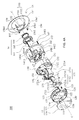
- FIG. 4A is an exploded perspective view of a light fixture in an embodiment of the present disclosure.
- FIG. 4B is another exploded perspective view of a light fixture in an embodiment of the present disclosure.
- FIG. 4C is an exploded side view of a light fixture in an embodiment of the present disclosure.
- FIG. 5A is a side view of a part assembly of a light fixture in an embodiment of the present disclosure.
- FIG. 5B is a side view of a part assembly of a light fixture in an embodiment of the present disclosure.
- FIG. 6A is a perspective view of a light fixture fixed to a carrier in an embodiment of the present disclosure.
- FIG. 6B is a side view of a light fixture fixed to a carrier in an embodiment of the present disclosure.
- FIG. 6C is an enlarged view of a circle A of FIG. 6A
- FIG. 7A is a top view of a second lid in an embodiment of the present disclosure.
- FIG. 7B is a top view of a second lid in an embodiment of the present disclosure.
- FIG. 8 is a perspective view of a carrier plate in an embodiment of the present disclosure.
- FIG. 9 is a cross-sectional view of a light fixture fixed to a carrier in an embodiment of the present disclosure.
- FIG. 10A is a schematic diagram of connection of a plurality of light fixtures in an embodiment of the present disclosure.
- FIG. 10B is a schematic diagram of connection of a plurality of light fixtures in an embodiment of the present disclosure.
- FIG. 10C is a schematic diagram of connection of a plurality of light fixtures in an embodiment of the present disclosure.
- FIG. 11 is an exploded perspective view of a light fixture in an embodiment of the present disclosure.
- FIG. 12 is a perspective view of the second lid comprising elastic components in the disengaged position in accordance with another embodiment of the present disclosure.
- FIG. 13 is a perspective view of the second lid of FIG. 12 with the elastic components in the engaged position.
- FIG. 14 is an exploded perspective view of a light fixture in accordance with another embodiment of the present disclosure.
- FIG. 15 is a cross-sectional view of the light fixture of FIG. 14 comprising the second lid in accordance with another embodiment of the present disclosure.
- FIG. 16 is a detailed cross-sectional view of the light fixture of FIG. 15 taken from Section 1504 shown in FIG. 15 .
- FIG. 17 is a bottom view of the second lid body of FIG. 15 .
- FIG. 18 is a detailed view of a pocket of the second lid body of FIG. 15 taken from Section 1701 shown in FIG. 17 .
- FIG. 1A shows a perspective view of a light fixture 100 in an embodiment of the present disclosure.
- FIG. 1B shows another perspective view of a light fixture 100 in an embodiment of the present disclosure.
- the light fixture 100 includes a first lid 11 , a first lid body 12 , a junction box 13 , a second lid body 14 , a second lid 15 , and a fastener 19 .
- the direction to the first lid 11 is defined as the upper direction
- the direction to the second lid 15 is defined as the lower direction. Therefore the order from top to bottom is the first lid 11 , the first lid body 12 , the junction box 13 , the second lid body 14 and a second lid 15 in FIG. 1A .
- the second lid body 14 has a plurality of first grooves 141 A, a plurality of second grooves 141 B and a plurality of third grooves 141 C.
- the widths of the first groove 141 A and the third groove 141 C are smaller than the width of the second groove 141 B.
- the first groove 141 A may also be greater than or equal to the width of the second groove 141 B in design.
- the depths of the first groove 141 A and the second groove 141 B may be the same or different.
- the depth of the third groove 141 C is greater than the depths of the first groove 141 A and the second groove 141 B.
- the first groove 141 A or/and the second groove 141 B or/and the third groove 141 C may increase the contact area of the second lid body 14 with an external environment (for example, air) to help heat dissipation.
- the fastener 19 has a first portion 191 and a second portion 192 located in the third groove 141 C.
- the second groove 141 B is used for receiving the second portion 192 therein, so that the light fixture 100 can be in the storage state (for example, placed in the package box) to reduce the occupied space or volume.
- the size of the hole in the carrier can be reduced. Details will be described later.
- a space S (referring to FIG. 9 ) is formed between the junction box 13 and the second lid body 14 .
- Air can flow into the space S through the first groove 141 A, the second groove 141 B and the third groove 141 C to form heat convection and increase heat dissipation.
- air can also flow from the space S to the first groove 141 A, the second groove 141 B and the third groove 141 C.
- the second lid 15 (or the light fixture 100 ) defines a central axis (C) and has a ring-shaped surface 151 , a top end 152 (referring to FIG. 4A ) and an inner side surface 153 extending from the ring-shaped surface 151 to the top end 152 .
- the inner side surface 153 is an sloped surface and defines a hole 15 H.
- the aperture (D 1 ) of the hole 15 H is reduced along the ring-shaped surface 151 toward the top end 152 and a light source module 16 passes through the hole 15 H and is surrounded by the inner side surface 153 .
- the inner side surface 153 has a tilt angle ( ⁇ ) with respect to the central axis and the tilt angle affects the far-field light distribution pattern and the light angle of the light fixture. For example, when the tilt angle is larger, the light distribution pattern and the light angle become larger. Conversely, when the tilt angle is smaller, the light distribution pattern and the light angle become smaller. Furthermore, when the light angle gets larger, the illuminance of the light fixture gets smaller and the light fixture will be prone to glare. For example, assuming two light fixtures (light fixture A and light fixture B) produce the same luminous flux.
- the tilt angle can be designed so that the light angle of the light fixture 100 is less than 100 degrees, or less than 60 degrees or less than 40 degrees.
- FIG. 2A shows another perspective view of the light fixture 100 in an embodiment of the present disclosure.
- the first lid 11 has two circular top plates 111 , two pull plates 112 and a plurality of buckles 113 .
- the top plate 111 can be removed so that half-inch or three-quarter inches of metallic flexible conduit or non-metallic conduit pass through the first lid 11 to enter the inside of the junction box 13 and be electrically connected with the connectors 172 A-C (referring to FIG. 3A ) disposed in the junction box 13 .
- the pull plate 112 is rotatable for open so that an external electric cord (wire or cable) (not shown) enters the inside of the junction box 13 and be electrically connected with the connectors 172 A-C (referring to FIG.
- FIG. 2C when the pull plate 112 shows an open state, an external electric cord (not shown) can pass through the first lid 11 to enter the inside of the junction box 13 and be electrically connected with the connectors 172 A-C (referring to FIG. 3A ) disposed in the junction box 13 , the details will be described later.
- FIG. 2B shows the pull plate 112 at a close state.
- the first lid 11 is fixed to the first lid body 12 by the plurality of buckles 113 .
- FIG. 3A shows another perspective view of the light fixture 100 in an embodiment of the present disclosure.
- FIG. 3B shows a top view of FIG. 3A .
- the first lid body 12 is hinged on the junction box 13 so that the first lid body 12 can be pivoted to show a close state (as shown in FIG. 1A ) or an open state (as shown in FIG. 3A ).
- An electronic control module 170 is disposed between the first lid body 12 and the junction box 13 , and includes an electronic control box 171 .
- the plurality of connectors 172 A-C (for example, product model: WAGO 773 or 221 series) are disposed in the junction box 13 .
- the two electric cords 173 A and 173 B pass out from the electronic control box 171 and are respectively connected with the connectors 172 A and 172 B.
- the connectors 172 A-C are not locked on any component (for example, not locked on the electronic control box 171 or the junction box 13 ). In other words, the connectors 172 A-C are freely movable or displaceable within the junction box 13 .
- the electric cords 173 A and 173 B are a flexible cord and can be flexed or bent. When a plurality of cords are to be electrically connected to each other, the cords can be twisted and wound together, and wound with insulating tape around the cords. However, through the connectors, multiple cords only need to be inserted into the connectors to form an electrical connection without winding procedure.
- the junction box 13 has a recess 131 .
- the recess 131 is a protruding portion 132 which protrudes toward the inside of the junction box 13 .
- the electronic control box 171 is fixed in the protruding portion 132 , and the protruding portion 132 can provide a surface so that the electronic control box 171 can be flatly attached on the surface.
- FIG. 4A shows an exploded perspective view of the light fixture 100 in an embodiment of the present disclosure.
- FIG. 4B shows another exploded perspective view of the light fixture 100 in an embodiment of the present disclosure.
- FIG. 4A and FIG. 4B are exploded perspective views of different views.
- FIG. 4C shows an exploded side view of the light fixture 100 in an embodiment of the present disclosure.
- the second lid 15 also includes an outer side surface 154 which extends from the surface 151 to the top end 152 .
- Three protrusions 155 are radially equidistantly disposed on the outer side surface 154 and protrude outwardly and are located adjacent to the top end 152 (referring to FIG. 7A ).
- Three elastic components 156 are respectively fixed to the three protrusions 155 by screws 157 . The disposition of the elastic component 156 helps to tightly fix the second lid 15 to the second lid body 14 or to easily remove it from the second lid body 14 , details will be described later.
- the position and number of the protrusion 155 and the elastic component 156 can be changed according to actual requirements, but not limited thereto.
- a light source assembly 16 includes a carrier 161 , a plurality of light emitting structures 162 disposed on the carrier 161 , a reflective structure 163 and a light source cover 164 .
- the carrier 161 has two positioning openings 161 H formed on the edges to facilitate the assembly of the reflective structure 163 thereon.
- the reflective structure 163 is disposed on the carrier 161 and surrounds the light emitting structure 162 , and has a protrusion 1631 protruding upward.
- the light source cover 164 is fixed to the reflective structure 163 and may be a mist shell or transparent shell, and can diffuse or homogenize the light emitted from the light emitting structure 162 , and prevent the generation of light spots.
- Each connecting port 165 is disposed on the carrier 161 and are electrically connected to the light emitting structure 162 .
- Each connecting port 165 has two metal holes 165 H (referring to FIG. 8 ) for circuit pins 176 to pass through and make electrical connection with the circuit pins 176 . Details will be described later.
- the light emitting structure 162 and the connecting port 165 can be fixed on the carrier 161 by surface bonding technique (SMT).
- the second lid body 14 has a body 142 , a shoulder 143 and a carrier support 144 .
- the shoulder 143 is connected to the body 142 and extends outward from the body 142 .
- the body 142 and the carrier support 144 define an internal space 142 S and an aperture (D 2 ) together.
- the second lid body comprises an inner surface 1421 .
- the first groove 141 A, the second groove 141 B, and the third groove 141 C are formed on an outer surface 1422 of the body 142 and do not penetrate the body 142 and thus are not in communication with the internal space 142 S.
- a first groove 141 A, a second groove 141 B and a third groove 141 C are formed on the outer surface 1422 of the body 142 and do not penetrate the body 142 .
- the grooves 141 A-C are not in communication with the internal space 142 S.
- the first groove 141 A, the second groove 141 B and the third groove 141 C can penetrate the body 142 and communicate with the internal space 142 S to increase heat convection.
- the grooves 141 A-C in FIG. 1A correspond to the protruding parts 146 A-C protruding inward in FIG. 4B .
- the screw 147 is disposed in the third groove 141 C.
- the fixing component 19 is screwed to the screw 147 through a hole 19 H of a first portion 192 (referring to FIG. 6C ).
- the fixing component 19 is used to clamp the light fixture 100 to a carrier (for example, a ceiling or a wall). Details will be described later.
- the junction box 13 has a body 130 .
- the body 130 has a bottom portion 1301 and a side portion 1302 .
- Two protruding elements 134 form the bottom portion 1301 and protrude downward, and respectively have two through holes 13 H for allowing the protruding lumps 1714 to pass through (detailed structure in FIG. 9 ).
- the protruding portion 132 (or the recess 131 ) is formed on the side portion 1302 of the body 130 and has a groove 1322 .
- the electronic control module 170 includes the electronic control box 171 .
- a circuit board 174 is disposed in the electronic control box 171 .
- the electric cords 173 A and 173 B are fixed on the circuit board 174 and are electrically connected with an electronic control component 175 on the circuit board 174 .
- the electronic control component 175 may include a bridge element, a capacitor, a resistor, an inductor, a transformer, or/and an IC to form a Linear circuit or a Switch circuit.
- the wireless receiving/transmitting module can also be fixed on the circuit board 174 .
- Two circuit pins 176 are formed on the circuit board 174 and are electrically connected with the electronic control component 175 , the electric cords 173 A- 173 B and the light emitting structure 162 . The connection of the circuit pin 176 and the light emitting structure 162 will be described later.
- the electronic control box 171 includes a box body 1711 and a box lid 1712 .
- the box lid 1712 has a hole 1712 H.
- the screw 1713 passes through the hole 1712 H to lock the box lid 1712 to the junction box 13 .
- the box lid 1712 has an arc protrusion 1712 A and an extension 1712 B.
- the arc protrusion 1712 A and the extension 1712 B define a space 1712 S together.
- the arc protrusion 1712 A and the groove 1322 form a capacity space for a cylinder 121 of the first lid body 12 to be received and rotated therein.
- the groove 1322 may have a circular cross-section, a non-circular or square cross-section.
- the box body 1711 has two protruding pieces 1714 protruding downwards and has two holes 17 H. Two holes 17 H are respectively formed in the two protruding pieces 1714 and penetrate the two protruding pieces 1714 for the circuit pins 176 passing through the protruding pieces 1714 (detailed structure in FIG. 9 ).
- the first lid body 12 has a body 120 , a cylinder 121 , two slope portions 122 , two recesses 123 , a first opening 124 and a second opening 125 .
- the first opening 124 is defined by the body 120 .
- the body 120 and the cylinder 121 define the second opening 125 together.
- a part of the cylinder 121 is disposed in the groove 1322 of the protrusion portion 132 of the junction box 13 , and the other part is disposed in a space 1712 S, whereby the cylinder 121 can be rotated so that the first lid body 12 can be pivoted relative to the junction box 13 to show a close state ( FIG. 1A ) or an open state ( FIG. 3A ).
- the cylinder 121 can be replaced by two separated circular protrusions.
- the slope portion 122 has a slope 1221 which is sloped from the inside to the outside and sloped from the top to the bottom, and is separated from the recess 123 . Therefore there is a gap 12 S between the slope portion 122 and the recess 123 (see FIG. 2C ).
- the slope portion 122 can be made of a material having elasticity.
- the first lid 11 has an upper plate 114 and a buckle 113 .
- the upper plate 114 has two round holes 11 H.
- the top plate 111 is disposed in the round hole 11 H and the diameter of the top plate 111 substantially matches the aperture of the round hole 11 H, so that the top plate 111 completely fills the round hole 11 H.
- the upper plate 114 completely covers the first opening 124 and the position of the top plate 111 is disposed relative to the first opening 124 . If a metallic flexible conduit or a non-metallic conduit is mounted on the light fixture 100 , the top plate 111 can be removed. Next, a metallic flexible conduit or a non-metallic conduit can pass through the round hole 11 H and the first opening 124 and into the junction box 13 . Since the space inside the junction box 13 is limited and when the diameter of the external cord is large, the external cord cannot be freely moved within the junction box 13 .
- the buckle 113 extends downward from the edge of the upper plate 114 , and engages with the recess 123 of the first lid body 12 during assembling.
- the pull plate 112 is disposed on the upper plate 114 and extends outward to exceed the edge of the upper plate 114 , so that the pull plate 112 can be opened or closed by an external force(for example, a hand or a wrench).
- the position of the pull plate 112 is relative to the slope portion 122 and covers the slope portion 122 .
- the pull plate 112 shows a close state (see FIG. 2B ).
- the pull plate 112 is in an open state (as shown in FIG.
- an external cord (cable or wire) can pass through the gap 12 S from the outside to enter into the junction box 13 and the external cord (cable or wire) can be fixed in the gap 12 S.
- the external cord (cable or wire) can easily enter the junction box 13 along the slope 1221 by the slope design of the two slope portions 122 .
- the slope portion 122 has elasticity, a portion of the slope portion 122 may be bent to catch the external cord so that the external cord is difficult to be pulled out.
- the slope design of the elastic slope portion and the diameter of the external cord is large so that the external cord is not easy to be bent, the external cord cannot be freely moved in the junction box 13 .
- the movement position of the external cord within the junction box 13 is limited due to the limitations of the slope, the space, and the cord diameter. Therefore, the free movement of the connectors 172 A-C and the bendable design of the electric cords 173 A-B allow the connectors 172 A-C and the electric cords 173 A-B to move in accordance with the position of the external cords. As a result, the external cords can be easily connected with the connectors 172 A-C to reduce the difficulty of assembly.
- FIG. 5A and FIG. 5B show a side view of a part assembly of the light fixture 100 in an embodiment of the present disclosure.
- FIG. 5A and FIG. 5B will describe the assembly flow of the light fixture 100 .
- the first lid 11 is engaged to the first lid body 12 .
- the buckle 113 is disposed in the recess 123 and the upper plate 114 completely covers the first opening 124 .
- the position of the top plate 111 is located at the position of the first opening 124 .
- the pull plate 112 is located on the slope portion 122 and the second opening 125 is not covered by the upper plate 114 .
- the circuit board 174 having the electronic control component 175 , the electric cords 173 A-B and the circuit pins 176 is disposed in the box body 1711 .
- the circuit pins 176 penetrate the protruding pieces 1714 and expose a portion thereof.
- Electric cords 173 A and 173 B are respectively connected to two of the connectors 172 A-C.
- the body box 1711 is attached and fixed on the surface of the protrusion portion 132 .
- the circuit pin 176 s also penetrate the hole 13 H of the protruding elements 134 and are exposed (as shown in FIG. 5A ).
- the second opening 125 exposes the arc protrusion 1712 A.
- the cylinder 121 of the first lid body 12 is disposed in the groove 1322 and the box lid 1712 and the box body 1711 is engaged with each other.
- the box lid 1712 is locked on the junction box 13 by the screws 1713 .
- the first lid body 12 and the junction box 13 are locked by the screw 117 to complete the first assembly 40 .
- a spring 118 is provided to sleeve the screw 117 for creating a spring force, so that the screw 117 can be substantially fixed in a position.
- the screw 117 needs to be loosened.
- the carrier 161 having the plurality of light emitting structures 162 is engaged with the carrier support 144 of the second lid body 14 and the connecting port 165 is aligned with the hole 14 H of the second lid body 14 .
- the screw 147 is disposed in the third groove 141 C and the fixing component 19 is screwed onto the screw 147 to complete a second assembly 41 .
- the reflective structure 163 and the light source cover 164 are engaged by using an ultrasonic bonding technique or using an adhesive, a fastener, or the like to complete a third assembly 42 .
- the circuit pins 176 exposed from the lower portion of the junction box 13 are aligned with the connecting ports 165 on the carrier 161 , and the circuit pins 176 are inserted into the connecting port 165 to assemble the first assembly 40 and the second assembly 41 .
- the protrusion 1631 of the reflective structure 163 is aligned with the positioning opening 161 H of the carrier.
- a screw 133 is provided to lock the junction box 13 , the second lid body 14 and the third assembly 42 to complete a fourth assembly 43 .
- the position of the connecting port 165 will be a certain distance from the body 142 .
- the electronic control box 171 (including the circuit board 174 ) needs to be disposed in a distance from the body 130 . Therefore, when the electronic control box 171 is fixed on the junction box 13 , the position of the electronic control box 171 can make the circuit pin 176 aligned with the connecting port 165 by the design of the protruding portion 132 of the junction box 13 .
- the design of the protruding portion 132 (forming the recess 131 ) can also reduce the manufacturing material of the junction box 13 , so as to reduce the manufacturing cost.
- the junction box 13 may not have the protruding portion 132 that means the recess 131 is not formed.
- the electronic control box 171 is fixed to the junction box 13 by the inward extension of the frame or rib, so that the circuit pin 176 is aligned with connecting port 165 .
- FIG. 6A shows a perspective view of the fourth assembly 43 fixed to a carrier 30 (for example, a ceiling) in an embodiment of the present disclosure.
- FIG. 6B shows a side view of the fourth assembly 43 fixed to the carrier 30 in an embodiment of the present disclosure.
- FIG. 6C is an enlarged view of a circle A of FIG. 6A .
- the fourth assembly 43 is passed through the opening of the carrier 30 .
- the first portion 191 of the fixing component 19 is screwed onto the screw 147 and the second portion 192 is located in the second groove 141 B (as shown in FIG. 1A ), and the shoulder 143 is exposed and abutted against the bottom surface 301 of the carrier 30 .
- the carrier 30 is located between the shoulder 143 and the fixing component 19 . If the fixing component 19 is not disposed in the second groove 141 B and is in an open state, the fixing component 19 will be gotten stuck in the opening, and the subsequent installation procedure cannot be continued. If the fixing component 19 is to be opened and can pass through the opening, the opening needs to be enlarged. Therefore, the second portion 192 of the fixing component 19 located in the second groove 141 B can reduce the overall volume and reduce the opening size of the carrier.
- the screw 147 is rotated clockwise (viewed from the bottom to the top), in the meantime the second portion 192 is rotated clockwise and away from the second groove 141 B to touch the third groove wall 1411 .
- the fixing component 19 shows an open state.
- the second portion 192 is not continuously rotated (due to the disposition of the third groove wall 1411 ) but is moved downward (moved in the direction to the carrier 30 ).
- the second portion 192 is lowered to contact the carrier 30 , the rotation can be continued to abut against or fasten the second portion 192 on the carrier 30 .
- the second lid 15 (not shown in FIG. 6A ) is loaded to complete the assembly of the light fixture 100 .
- FIG. 7A is a top view of the second lid 15 .
- a protrusion 155 includes a cylinder 1551 and a baffle 1552 .
- Each of the three baffles 1552 is located on the same side (It can be left or right side of the corresponding cylinder 1551 and be the left side in present embodiment).
- the elastic component 156 is rotated clockwise as shown in FIG. 7B (viewed from top to bottom), the elastic component 156 is blocked by the baffle 1552 and cannot be further rotated.
- the elastic component 156 can be rotated counterclockwise until it touches the outer side surface 154 .
- the degree of freedom for the rotation of the elastic member 156 in the clockwise direction is smaller than the degree of freedom for the rotation in the counterclockwise direction (second rotation direction).
- the elastic component 156 has a top portion 1561 , an extending portion 1562 and a bottom portion 1563 .
- the top portion 1561 is rotated to be fixed to the cylinder 1551 .
- the extending portion 1562 extends obliquely downward from the top portion 1561 .
- the bottom portion 1563 extends outward from the extending portion 1562 .
- the extending direction of the extending portion 1562 is different from the extending direction of the bottom portion 1563 (not perpendicular to each other).
- the bottom portion 1563 comprises one or more teeth 1564 .
- the bottom portion 1563 comprises two teeth 1564 ; in other embodiments, the bottom portion 1563 comprises teeth 1564 greater or fewer than two.
- the three vertices A 1 , A 2 , A 3 of the three elastic components 156 are oriented in different directions rather than toward the hole 15 H.
- Three elastic components 156 are rotated to make the three vertices A 1 , A 2 , A 3 toward the holes 15 H slowly.
- the three vertices A 1 , A 2 , A 3 of the three elastic components 156 are substantially oriented the center of the hole 15 H.
- the elastic component 156 is abutted against on the baffle 1552 first (as shown in FIG. 7B ). Then, the second lid 15 is aligned with the second lid body 14 and the extending portion 1562 is overlapped and contacted with the shoulder 143 . Apply a force to insert the second lid 15 into the second lid body 14 to complete the assembly. At this time, the extending portion 1562 is bent, and the extending portion 1562 and the bottom portion 1563 are in contact with the inner surface 1421 of the second lid body 14 .
- the teeth 1564 of the bottom portion 1563 can engage with the inner surface 1421 and the bottom portion 1563 is locked to the inner surface 1421 (a frictional force is generated) so that the second lid 15 will not drop.
- the second lid 15 can be rotated counterclockwise to rotate the elastic component 156 to a position as shown in FIG. 7A .
- the elastic component 156 is rotated and moved, the extending portion 1562 and the bottom portion 1563 are no longer in contact with the inner surface 1421 (or the contact area between the inner surface 1421 and the extending portion 1562 , the bottom portion 1563 becomes smaller).
- the locking force (friction) between the elastic component 156 and the second lid body 14 is also disappeared accordingly. Therefore the second lid 15 can be easily taken out and removed.
- the assembly of the light fixture 100 is not limited to the above-mentioned.
- the carrier 161 can be assembled on the second lid 14 first. Then, after assembling the junction box 13 on the second lid body 14 , the box body 1711 (including the circuit board 174 having the electronic control component 175 , the electric cords 173 A, 173 B and the circuit pins 176 ) is assembled on the junction box 13 to make the circuit pins 176 plugged in the connecting ports 165 . Finally, the box lid 1712 , the first lid body 12 and the first lid 11 are assembled.
- the first lid 11 may be a metal plate (for example, a low carbon steel plate, a stainless steel plate, a galvanized steel plate or an aluminum plate) or a plastic plate.
- the first lid 11 and the top plate 111 may be formed by the punch method.
- the material of the first lid body 12 may be plastic (for example, PA (Polyamide), PC (Polycarbonate), or ABS (Acrylonitrile Butadiene Styrene).
- the material of the junction box 13 may be metal or plastic (for example, PA (Polyamide), PC (Polycarbonate), or ABS (Acrylonitrile Butadiene Styrene).
- the material of the second lid body 14 may be metal (for example, aluminum, steel, copper, iron) or plastic (for example, PA (Polyamide), PC (Polycarbonate), ABS (Acrylonitrile Butadiene Styrene), PBT (Polybutylene terephthalate) and can be used as a heat sink.
- the material of the second lid 15 may be metal or plastic (for example, PA (Polyamide), PC (Polycarbonate), or ABS (Acrylonitrile Butadiene Styrene).
- the material of the elastic component 156 may be plastic (for example, PA (Polyamide), POM (Polyoxymethylene) or metal (for example, low carbon steel, high carbon steel, stainless steel).
- the material of the reflective structure 163 may be PC (Polycarbonate) or ABS (Acrylonitrile Butadiene Styrene) and may achieve a V0 fire-protection rating in UL94.
- the carrier 161 may be a printed circuit board.
- the material of the light source cover 164 may be PC (Polycarbonate) or ABS (Acrylonitrile Butadiene Styrene).
- the fixing component 19 may be metal (for example, aluminum, steel, copper, iron) or plastic (for example, PA (polyamide), PC (Polycarbonate), or ABS (Acrylonitrile Butadiene Styrene). All the above-mentioned plastic materials can achieve V0 fire-protection rating in UL94.
- thermal materials such as graphite, ceramic powder, and/or carbon nanotubes may be doped into the above-mentioned plastic material to form thermally conductive plastic.
- the screw is used for joint in the present disclosure.
- bolts, studs, nuts, or other suitable fasteners may also be used for joint.
- the light emitting structure 162 includes a first light emitting group 162 A and a second light emitting group 162 B.
- the first light emitting group 162 A includes four light emitting units and the second light emitting group 162 B includes six light emitting units.
- the second light emitting group 162 B is disposed at outside of the first light emitting group 162 A and surrounds the first light emitting group 162 A.
- the number and arrangement of the first light emitting group 162 A and the second light emitting group 162 B can be changed according to the actual requirements, but not limited thereto.
- the first light emitting group 162 A and the second light emitting group 162 B may emit the same color light or different color light.
- the first light emitting group 162 A emits red light and the second light emitting group 162 B emits blue light.
- the first light emitting group 162 A and the second light emitting group 162 B may emit white light and may have the same color temperature (for example, the first light emitting group 162 A and the second light emitting group 162 B emit warm white light (2200 K to 4000 K) or cool white light (4000K ⁇ 6500K) or different color temperature (for example, the first light emitting group 162 A emits warm white light (2200K ⁇ 4000K) and the second light emitting group 162 B emits cool white light (4000K ⁇ 6500K); or the first light emitting group 162 A emits warm white light (2200K to 4000K, for example, 2700K) and the second light emitting group 162 B also emits warm white light (2200K to 4000K, for example, 3000K).
- the light emitting unit may include a package structure.
- a light emitting chip is fixed in the package structure and a transparent glue cover the light emitting chip.
- the transparent glue contains wavelength conversion particles
- the wavelength conversion particles can convert the first light emitted by the light emitting chip into a second light.
- the first light and the second light can be mixed to form a white light.
- the light emitting chip may include a growth substrate, a first type semiconductor layer, an active layer, a second type semiconductor layer and two electrodes.
- two connecting ports 165 are disposed on the carrier plate 161 .
- two circuit pins 176 are disposed on the circuit board 174 and are only electrically connected with one connecting port 165 to provide power to the light emitting structure 162 (another connecting port 165 is not electrically connected with the circuit board).
- the light emitting units can be connected in parallel or in series, and all the light emitting units can emit light at the same time or not at the same time.
- circuit pins can be provided on the circuit board 174 to respectively form electrical connections with two connecting ports 165 (two circuit pins disposed on one connection port), so that the first light emitting group 162 A and the second light emitting group 162 B (dual channel) can be respectively controlled.
- the number of circuit pins and connecting ports can be changed according to actual requirements, but not limited thereto.
- FIG. 9 shows a cross-sectional view of the light fixture 100 in an embodiment of the present disclosure.
- the circuit pin 176 is an L-shape and passes through the electronic control box 171 , the junction box 13 and the second lid body 14 to be inserted into the connecting port 165 on the carrier 161 .
- the protruding piece 1714 surrounds the circuit pin 176 .
- the protruding element 134 surrounds the protruding piece 1714 and the circuit pin 176 .
- the circuit pin 176 and the second lid body 14 can be separated by a sufficient distance to avoid arcing.
- the protruding piece 1714 and the protruding element 134 are made of plastic material and can also avoid flashover.
- the bottom of the protruding piece 1714 has a chamfered inclined structure 1715 to facilitate the assembly with the protruding element 134 .
- Other related descriptions can be referred to other paragraphs.
- the light emitting structure 162 When the light emitting structure 162 emits light, the light emitted from the light emitting structure 162 passes through the light source cover 164 and is emitted outward through the second lid 15 .
- the heat generated by the light emitting structure 162 can be transferred to the carrier 162 , the second lid body 14 , the second lid 15 and heat exchange is performed with the external environment.
- a temperature measurement can be performed to measure the temperature of the carrier 162 .
- the temperature measurement steps are as follows:
- the maximum aperture of the second lid body 14 is 4 inches
- Step 2 The light fixture 100 is passed through the hole and disposed in the wooden box, and only the second lid 15 is exposed to the external environment;
- Step 3 Fill the wooden box with thermal insulation material (fiber, product model GREENFIBER@, INS541LD) to cover the light fixture 100 so that the light fixture 100 is completely buried in the thermal insulation material; and
- Step 4 Provide power to the light fixture 100 to emit light at least two hours (in a thermally stable state). Dig a small hole in the light source cover 164 and use a thermocouple to pass through the light source cover 164 , and measure the temperature the position of the carrier 161 next to the light emitting structure 162 which is located in the center of the carrier 161 (in this embodiment, the temperature of the carrier 161 next to the first light emitting group 162 A is measured and is referred to as a center temperature).
- the center temperature can be measured as 70 to 105 degrees through the above-mentioned thermal measurement step.
- the junction box 13 and the second lid body 14 are not tightly connected.
- a space S is formed between the junction box 13 and the second lid body 14 so that the heat generated by the light emitting structure 162 is not easily transmitted to the junction box 13 .
- Most of the heat is conducted downward and transferred to the second lid 15 via the metal second lid body 14 to exchange heat with the outside environment.
- the electronic control module in the junction box 13 can be prevented from being damaged due to excessive temperature, and the light emitting structure 162 can also be prevented from reducing the efficiency due to excessive temperature.
- the space S makes the second lid body 14 to have a part contacted with the air and without contacted with the heat insulating material.
- the junction box 13 is a plastic material, the manufacturing cost can be reduced.
- the center temperature can be measured that is greater than 105 and less than 130 degrees through the above-mentioned thermal measurement steps.
- the light fixture of the present disclosure can be easily assembled on a carrier (for example, the design of the elastic component 156 , the spring 118 , or the fixing component 19 ).
- the second lid 15 of different colors and shapes can be selected according to the needs of the environment to increase overall appearance.
- the arrangement of the top plate 111 and the pull plate 112 allows external cords inserted or removed, and simplifies the design of external cords.
- one inlet one top plate, inlet
- three outlets two pull plates and one top plate, outlet
- FIG. 10A in a space 800 , when there are a plurality of light fixtures (four) to be disposed, if there is no design of the top plate and the pull plate, each light fixture 100 A ⁇ D must be directly connected to the external power source 801 (commercial power).
- the light fixture itself can be served as a connection relay body through the design of the top plate and the pull plate.
- light fixture 100 A is connected to an external power source; light fixture 100 C is connected to light fixture 100 A; light fixture 100 D is connected to light fixture 100 C; and light fixture 100 B is connected to light fixture 100 D.
- the number and shape of the top plate and pull plate can be changed according to actual requirements, but not limited thereto.
- FIG. 11 shows an exploded perspective view of a light fixture 200 in an embodiment of the present disclosure.
- the light fixture 200 has a similar structure to the light fixture 100 , wherein the same symbols or marks correspond to elements or apparatus that have similar or identical elements or apparatus.
- the second lid body 14 ′ further includes a middle portion 148 connected between the body 142 and the carrier support 144 .
- the first groove 141 A is located in the middle portion 148 .
- the third groove 141 C is located in the body 142 .
- the second lid body 14 ′ does not include the second groove 141 B so that the fixing component 19 is only rested on the middle portion 148 in a stowed state.
- the middle portion 148 By the buffer design of the middle portion 148 , the aperture (D 2 , for example: 6 inches) of the second lid body 14 ′ can be enlarged, and the sizes of the first lid 11 , the first lid body 12 and the junction box 13 do not need to be changed. Furthermore, the middle portion 148 can also increase the heat dissipation area so that the light fixture 200 can be operated at high wattages.
- FIGS. 12 and 13 show perspective views of the second lid 15 of FIGS. 1A and 1B comprising an elastic component 156 in accordance with the present disclosure.
- the elastic component 156 can be in the disengaged position in FIG. 12 and the elastic component 156 can be angled inward in a rotational direction 1202 relative to a radial direction 1201 of the central axis (C).
- the elastic component 156 can be in the engaged position and aligned with the radial direction 1201 of the central axis (C) in FIG. 13 .
- the elastic component 156 can extend outwards in the radial direction 1201 relative to the central axis (C) in the engaged position without extending axially upward or downward with respect to the central axis (C).
- the elastic component 156 can also extend axially upward or downward with respect to the central axis (C).
- a first beveled edge 1203 is formed in the bottom portion 1563 .
- the elastic component 156 can contain a retention tab 1204 disposed proximately to the bottom portion 1563 .
- Each retention tab 1204 can extend outwards from the respective elastic component 156 proximate to the bottom portion 1563 , and each retention tab 1204 has a second beveled edge 1205 .
- the beveled edges 1203 , 1205 can engage with a plurality of grooves or a plurality of ridges defined by the inner surface 1421 , similar to the plurality of grooves 1505 shown in FIGS. 15 and 16 .
- FIG. 14 is an exploded perspective view of a light fixture 100 in accordance with another embodiment of the present disclosure.
- the light fixture 100 can be sized for a 6′′ diameter nominal opening.
- the second lid body 14 comprises protuberances 1401 which can extend outwards from the body 142 of the second lid body 14 and down to the shoulder 143 .
- the protuberances 1401 can correspond to pockets 1501 shown in FIG. 15 which can extend outwards from the second lid body bore 1502 shown in FIG. 15 , and the pockets 1501 can receive the elastic component 156 of the second lid 15 .
- the light fixture 100 of the present embodiment comprises a second lid 15 and elastic component 156 in accordance with another embodiment of the present disclosure.
- the second lid 15 comprises three elastic components 156 which can be equally circumferentially spaced around the second lid 15 .
- the elastic component 156 comprises the first beveled edges 1203 , the retention tabs 1204 , and the second beveled edges 1205 , and in the present embodiment, the elastic component 156 can be attached and rotationally fixed to bases 1403 .
- the bases 1403 can be disposed around the outer side surface 154 of the second lid 15 . In other embodiments, the bases 1403 can be disposed at the top end 152 shown in FIG. 15 .
- a slot 1402 can be defined by the base 1403 and the elastic component 156 can each comprise a locking tab 1503 shown in FIG. 15 at the top portion 1561 .
- the locking tabs 1503 can be received and secured within the slots 1402 to secure each elastic component 156 to the respective base 1403 .
- FIG. 15 is a cross-sectional view of the light fixture 100 of FIG. 14 comprising the second lid 15 and second lid body 14 in accordance with another embodiment of the present disclosure.
- the second lid 15 comprises two elastic components 156 of the embodiment of FIG. 14 secured to two bases 1403 positioned opposite from one another.
- FIG. 16 is a detailed cross-sectional view of the light fixture 100 of FIG. 15 taken from Section 1504 shown in FIG. 15 .
- the inner surface 1421 can define the pockets 1501 which can extend radially outwards from the second lid body bore 1502 within the respective protuberances 1401 .
- the pluralities of grooves 1505 can be defined by the inner surface 1421 within each pocket 1501 .
- the plurality of grooves 1505 can be defined by adjacent ridges of a plurality of raised ridges 1601 . In other embodiments, the grooves 1505 can extend into the inner surface 1421 .
- the bottom portions 1563 of the elastic component 156 can be received by the pockets 1501 which can cause the bottom portions 1563 to deflect radially inward and axially downward with respect to the central axis (C).
- a pocket chamfer 1506 can be defined between a bottom second lid body end 1507 and each of the pockets 1501 . The angled pocket chamfer 1506 can guide the bottom portions 1563 radially inward when the second lid 15 is aligned and inserted into the second lid body bore 1502 .
- Deflection of the bottom portions 1563 can engage the beveled edges 1203 , 1205 with the respective pluralities of grooves 1505 , and the elastic component 156 can exert a residual radially outward force acting against the grooves 1505 to prevent the second lid 15 from being withdrawn from the second lid body bore 1502 .
- FIG. 17 is a bottom view of the second lid body 14 of the light fixture 100 of FIG. 15
- FIG. 18 is a detailed view of one of the pockets 1501 of FIG. 17 taken from Section 1701 shown in FIG. 17 .
- the pockets 1501 can extend outwards from a bottom opening 1702 of the second lid body bore 1502 .
- each pocket 1501 comprises a first pocket sidewall surface 1703 , a second pocket sidewall surface 1704 , and a pocket back wall surface 1705 .
- the pocket back wall surface 1705 can extend between the respective pocket sidewall surfaces 1703 , 1704 , and the pocket back wall surfaces 1705 can be substantially perpendicular to the radial direction 1201 of the central axis (C).
- the inner surface 1421 can define the plurality of grooves 1505 on the pocket back wall surfaces 1705 , and the grooves 1505 can extend between the adjacent pocket sidewall surfaces 1703 , 1704 , substantially perpendicular to the radial direction 1201 of the central axis (C).
- a first angle ⁇ 1 can be defined between the first pocket sidewall surface 1703 and the pocket back wall surface 1705
- a second angle ⁇ 2 can be defined between the second pocket sidewall surface 1704 and the pocket back wall surface 1705 , as shown in FIG. 18
- the first pocket sidewall surface 1703 can be a square pocket sidewall surface which can be substantially perpendicular to the adjacent pocket back wall surface 1705 and parallel to the radial direction 1201 of the central axis (C).
- the first angle ⁇ 1 can be substantially equal to 90-degress.
- the second pocket sidewall surface 1704 can be an angled pocket sidewall surface
- the second angle 74 2 can be an obtuse angle, such as 135-degrees for example and without limitation. Values of the angles are not limiting and are provided for exemplary purposes. In other embodiments, values of the angles ⁇ 1 , ⁇ 2 are larger or smaller than the aforementioned value.
- the second lid 15 shown in FIG. 15 cannot be withdrawn from the second lid body bore 1502 of the second lid body 14 .
- Rotating the second lid 15 relative to the second lid body 14 can make the bottom portions 1563 of the elastic component 156 in contact with the second pocket sidewall surfaces 1704 .
- further rotation of the bottom portions 1563 towards the second pocket sidewall surfaces 1704 can deflect the bottom portions 1563 radially inward with respect to the central axis (C), thereby disengaging the beveled edges 1203 , 1205 (shown in FIG. 15 ) from the grooves 1505 .
- the second pocket sidewall surfaces 1704 can act as ramps which can lift the beveled edges 1203 , 1205 out of the grooves 1505 .
- both of the pocket sidewall surfaces 1703 , 1704 can be angled pocket sidewall surfaces, and the second lid 15 can be rotated in either direction relative to the second lid body 14 to disengage the elastic component 156 and release the second lid 15 from the second lid body 14 .
- the second lid 15 can be re-secured to the second lid body 14 by simply aligning the elastic component 156 with the pockets 1501 and stabbing the top end 152 into the second lid body bore 1502 until a second lid rim 1508 (shown in FIG. 15 ) contacts the shoulder 143 . Stabbing the top end 152 into the second lid body bore 1502 comprises axially translating the second lid 15 along the central axis (C) without rotating the second lid 15 about the central axis (C).
- the grooves 1505 can be defined by the inner surface 1421 within the second lid body bore 1502 rather than within the pockets 1501 .
- the grooves 1505 can be broken into circumferential arc-shaped portions with ungrooved portions of the inner surface 1421 circumferentially spaced between grooved portions of the inner surface 1421 .
- the bottom portions 1563 of the elastic component 156 can be aligned with the grooved portions to secure the second lid 15 to the second lid body 14
- the bottom portions 1563 of the elastic component 156 can be aligned with the ungrooved portions to release the second lid 15 from the second lid body 14 .
- the second lid body 14 comprises metal, such as aluminum, steel, zinc alloy, or any other suitable metal, and the second lid body 14 can act as a heat sink to draw heat away from the light source assembly 16 .
- the second lid body 14 comprises plastic material, such as polycarbonate, acrylonitrile butadiene styrene, or any other suitable plastic.
- the second lid 15 can act as the heat sink, and the second lid 15 comprises heat conductive material such as a metal to draw heat away from the light source assembly 16 .
- the elastic component 156 defining the teeth 1564 can be desirable because the teeth 1564 can cut directly into the second lid body 14 without requiring grooves 1505 to engage. Because metal can be expensive to form and machine, omitting the grooves 1505 can save on manufacturing costs and manufacturing steps.
- the elastic component 156 having the beveled edges 1203 , 1205 can be used with a metallic second lid body 14 having the grooves 1505 .
- grooves 1505 or ridges 1601 can be formed easily and economically, and the elastic component 156 defining teeth 1564 , beveled edges 1203 , 1205 , or a combination thereof can be utilized.
- the second lid 15 can be easily installed and removed from the second lid body 14 by one hand. For example, an installer working on a ladder can hold the ladder with one hand and use the other hand to install or remove the second lid 15 .
- the second lid 15 is simply installed by stabbing the top end 152 into the second lid body bore 1502 so that the elastic component 156 engages with the inner surface 1421 .
- the second lid 15 can be axially stabbed into the second lid body bore 1502 without a twisting or rotational motion as required by a threaded retention mechanism.
- the second lid rim 1508 can be positioned flush with the shoulder 143 each time without the need for adjustment because the shoulder 143 can act as a positive stop for the second lid rim 1508 . This eliminates the need for adjusting the light fixture 100 at height in order to eliminate gaps between the second lid rim 1508 and the ceiling.
Landscapes
- Engineering & Computer Science (AREA)
- General Engineering & Computer Science (AREA)
- Microelectronics & Electronic Packaging (AREA)
- Power Engineering (AREA)
- Physics & Mathematics (AREA)
- Optics & Photonics (AREA)
- Non-Portable Lighting Devices Or Systems Thereof (AREA)
Abstract
Description
Claims (20)
Applications Claiming Priority (3)
| Application Number | Priority Date | Filing Date | Title |
|---|---|---|---|
| CN201710429282 | 2017-06-08 | ||
| CN201710429282.0 | 2017-06-08 | ||
| CN201710429282 | 2017-06-08 |
Publications (2)
| Publication Number | Publication Date |
|---|---|
| US20180356056A1 US20180356056A1 (en) | 2018-12-13 |
| US10386026B2 true US10386026B2 (en) | 2019-08-20 |
Family
ID=64563284
Family Applications (1)
| Application Number | Title | Priority Date | Filing Date |
|---|---|---|---|
| US16/002,423 Active US10386026B2 (en) | 2017-06-08 | 2018-06-07 | Light fixture |
Country Status (2)
| Country | Link |
|---|---|
| US (1) | US10386026B2 (en) |
| CN (1) | CN109027714A (en) |
Cited By (1)
| Publication number | Priority date | Publication date | Assignee | Title |
|---|---|---|---|---|
| US20190203894A1 (en) * | 2018-01-04 | 2019-07-04 | Xiamen Eco Lighting Co. Ltd. | Downlight apparatus |
Families Citing this family (4)
| Publication number | Priority date | Publication date | Assignee | Title |
|---|---|---|---|---|
| US11050230B1 (en) * | 2018-07-09 | 2021-06-29 | Arlington Industries, Inc. | Electrical box for mounting an electrical device or fixture on a suspended ceiling T-bar or intersection of a T-bar grid |
| US11525557B2 (en) * | 2019-04-11 | 2022-12-13 | Xiamen Eco Lighting Co. Ltd. | Downlight apparatus |
| US10851971B1 (en) * | 2020-02-17 | 2020-12-01 | Signify Holding B.V. | Adjustable light fixtures |
| CN116877943B (en) * | 2023-09-06 | 2023-12-01 | 山西星心半导体科技有限公司 | Lamp bead encapsulation processing device |
Citations (4)
| Publication number | Priority date | Publication date | Assignee | Title |
|---|---|---|---|---|
| US20150233537A1 (en) | 2012-03-23 | 2015-08-20 | Cree, Inc. | Direct attach ceiling-mounted solid state downlights |
| US9310038B2 (en) | 2012-03-23 | 2016-04-12 | Cree, Inc. | LED fixture with integrated driver circuitry |
| US9494294B2 (en) | 2012-03-23 | 2016-11-15 | Cree, Inc. | Modular indirect troffer |
| US20170307198A1 (en) * | 2016-04-25 | 2017-10-26 | Ecoled Ventures Limited | Ssl can light fixture with built-in junction box |
Family Cites Families (3)
| Publication number | Priority date | Publication date | Assignee | Title |
|---|---|---|---|---|
| CN102588756B (en) * | 2011-01-13 | 2014-05-07 | 光宝电子(广州)有限公司 | Lighting fixture |
| CN203686647U (en) * | 2013-12-17 | 2014-07-02 | 苏州欧普照明有限公司 | Lamp |
| CN105090766B (en) * | 2014-04-15 | 2017-12-08 | 陈伟东 | Led lamp |
-
2018
- 2018-06-07 US US16/002,423 patent/US10386026B2/en active Active
- 2018-06-08 CN CN201810588870.3A patent/CN109027714A/en active Pending
Patent Citations (4)
| Publication number | Priority date | Publication date | Assignee | Title |
|---|---|---|---|---|
| US20150233537A1 (en) | 2012-03-23 | 2015-08-20 | Cree, Inc. | Direct attach ceiling-mounted solid state downlights |
| US9310038B2 (en) | 2012-03-23 | 2016-04-12 | Cree, Inc. | LED fixture with integrated driver circuitry |
| US9494294B2 (en) | 2012-03-23 | 2016-11-15 | Cree, Inc. | Modular indirect troffer |
| US20170307198A1 (en) * | 2016-04-25 | 2017-10-26 | Ecoled Ventures Limited | Ssl can light fixture with built-in junction box |
Cited By (1)
| Publication number | Priority date | Publication date | Assignee | Title |
|---|---|---|---|---|
| US20190203894A1 (en) * | 2018-01-04 | 2019-07-04 | Xiamen Eco Lighting Co. Ltd. | Downlight apparatus |
Also Published As
| Publication number | Publication date |
|---|---|
| CN109027714A (en) | 2018-12-18 |
| US20180356056A1 (en) | 2018-12-13 |
Similar Documents
| Publication | Publication Date | Title |
|---|---|---|
| US10386026B2 (en) | Light fixture | |
| US8714785B2 (en) | Cap, socket device, and luminaire | |
| EP2270385B1 (en) | Lamp | |
| CN101970932B (en) | Lighting device package and LED component | |
| US9903548B2 (en) | Fixture mounting system | |
| CA2735632C (en) | Multiple led bulb with thermal management features | |
| US20120243230A1 (en) | Heat transfer assembly for led-based light bulb or lamp device | |
| EP2224161A1 (en) | Lighting device and lighting fixture | |
| JP6010116B2 (en) | Socket, lighting module, and lighting fixture | |
| CN101675289A (en) | Led connector assembly with heat sink | |
| US5964516A (en) | Night light with wall outlet shield | |
| EP2466195B1 (en) | Lighting device | |
| JP2015519704A (en) | Solid state light using aligned light guide and integrated vented heat conductor | |
| KR101630999B1 (en) | Light-emitting means and use | |
| JP2011108396A (en) | Lamp with base, and lighting fixture | |
| CN205782424U (en) | Ligthing paraphernalia | |
| WO2012160688A1 (en) | Illuminating apparatus | |
| JP2022173450A (en) | lighting equipment | |
| WO2019042360A1 (en) | Led lamp | |
| WO2014172610A2 (en) | Omni-directional led lamp | |
| JP2014082068A (en) | Lighting device | |
| JP6663663B2 (en) | Compact fluorescent LED lamp | |
| JP7019207B2 (en) | Lighting equipment | |
| CN107110449B (en) | Thin lighting device and attachment member and kit comprising same | |
| JP2021007114A (en) | Lighting fixture |
Legal Events
| Date | Code | Title | Description |
|---|---|---|---|
| AS | Assignment |
Owner name: EPISTAR CORPORATION, TAIWAN Free format text: ASSIGNMENT OF ASSIGNORS INTEREST;ASSIGNORS:PHILLIPS, FREDERIC PERRY;HU, WEI-CHIANG;SIGNING DATES FROM 20180606 TO 20180607;REEL/FRAME:046017/0128 |
|
| FEPP | Fee payment procedure |
Free format text: ENTITY STATUS SET TO UNDISCOUNTED (ORIGINAL EVENT CODE: BIG.); ENTITY STATUS OF PATENT OWNER: LARGE ENTITY |
|
| AS | Assignment |
Owner name: ECOLED VENTURE CO., LIMITED, HONG KONG Free format text: CORRECTIVE ASSIGNMENT TO CORRECT THE RECEIVING'S PARTY TO ADD SECOND ASSIGNEE'S NAME PREVIOUSLY RECORDED AT REEL: 046017 FRAME: 0128. ASSIGNOR(S) HEREBY CONFIRMS THE ASSIGNMENT;ASSIGNORS:PHILLIPS, FREDERIC PERRY;HU, WEI-CHIANG;SIGNING DATES FROM 20180606 TO 20180607;REEL/FRAME:047512/0806 Owner name: EPISTAR CORPORATION, TAIWAN Free format text: CORRECTIVE ASSIGNMENT TO CORRECT THE RECEIVING'S PARTY TO ADD SECOND ASSIGNEE'S NAME PREVIOUSLY RECORDED AT REEL: 046017 FRAME: 0128. ASSIGNOR(S) HEREBY CONFIRMS THE ASSIGNMENT;ASSIGNORS:PHILLIPS, FREDERIC PERRY;HU, WEI-CHIANG;SIGNING DATES FROM 20180606 TO 20180607;REEL/FRAME:047512/0806 |
|
| AS | Assignment |
Owner name: EPISTAR CORPORATION, TAIWAN Free format text: ASSIGNMENT OF ASSIGNORS INTEREST;ASSIGNOR:ECOLED VENTURE CO., LIMITED;REEL/FRAME:048060/0716 Effective date: 20190118 |
|
| STPP | Information on status: patent application and granting procedure in general |
Free format text: RESPONSE TO EX PARTE QUAYLE ACTION ENTERED AND FORWARDED TO EXAMINER |
|
| STPP | Information on status: patent application and granting procedure in general |
Free format text: NOTICE OF ALLOWANCE MAILED -- APPLICATION RECEIVED IN OFFICE OF PUBLICATIONS |
|
| STPP | Information on status: patent application and granting procedure in general |
Free format text: PUBLICATIONS -- ISSUE FEE PAYMENT VERIFIED |
|
| STCF | Information on status: patent grant |
Free format text: PATENTED CASE |
|
| MAFP | Maintenance fee payment |
Free format text: PAYMENT OF MAINTENANCE FEE, 4TH YEAR, LARGE ENTITY (ORIGINAL EVENT CODE: M1551); ENTITY STATUS OF PATENT OWNER: LARGE ENTITY Year of fee payment: 4 |