US10378646B2 - Shift control system for vehicle and shift control method for vehicle - Google Patents
Shift control system for vehicle and shift control method for vehicle Download PDFInfo
- Publication number
- US10378646B2 US10378646B2 US15/794,777 US201715794777A US10378646B2 US 10378646 B2 US10378646 B2 US 10378646B2 US 201715794777 A US201715794777 A US 201715794777A US 10378646 B2 US10378646 B2 US 10378646B2
- Authority
- US
- United States
- Prior art keywords
- shift
- vehicle
- vehicle speed
- sensors
- electronic control
- Prior art date
- Legal status (The legal status is an assumption and is not a legal conclusion. Google has not performed a legal analysis and makes no representation as to the accuracy of the status listed.)
- Expired - Fee Related, expires
Links
- 238000000034 method Methods 0.000 title claims description 10
- 230000001133 acceleration Effects 0.000 claims abstract description 27
- 230000007935 neutral effect Effects 0.000 claims abstract description 22
- 230000007257 malfunction Effects 0.000 abstract description 36
- 230000008859 change Effects 0.000 abstract description 6
- 230000002159 abnormal effect Effects 0.000 description 2
- 230000000994 depressogenic effect Effects 0.000 description 2
- 230000005540 biological transmission Effects 0.000 description 1
- 230000007423 decrease Effects 0.000 description 1
- 238000001514 detection method Methods 0.000 description 1
- 238000010348 incorporation Methods 0.000 description 1
- 238000012986 modification Methods 0.000 description 1
- 230000004048 modification Effects 0.000 description 1
- 239000000758 substrate Substances 0.000 description 1
Images


Classifications
-
- F—MECHANICAL ENGINEERING; LIGHTING; HEATING; WEAPONS; BLASTING
- F16—ENGINEERING ELEMENTS AND UNITS; GENERAL MEASURES FOR PRODUCING AND MAINTAINING EFFECTIVE FUNCTIONING OF MACHINES OR INSTALLATIONS; THERMAL INSULATION IN GENERAL
- F16H—GEARING
- F16H61/00—Control functions within control units of change-speed- or reversing-gearings for conveying rotary motion ; Control of exclusively fluid gearing, friction gearing, gearings with endless flexible members or other particular types of gearing
- F16H61/12—Detecting malfunction or potential malfunction, e.g. fail safe; Circumventing or fixing failures
-
- F—MECHANICAL ENGINEERING; LIGHTING; HEATING; WEAPONS; BLASTING
- F16—ENGINEERING ELEMENTS AND UNITS; GENERAL MEASURES FOR PRODUCING AND MAINTAINING EFFECTIVE FUNCTIONING OF MACHINES OR INSTALLATIONS; THERMAL INSULATION IN GENERAL
- F16H—GEARING
- F16H59/00—Control inputs to control units of change-speed-, or reversing-gearings for conveying rotary motion
- F16H59/02—Selector apparatus
- F16H59/04—Ratio selector apparatus
- F16H59/044—Ratio selector apparatus consisting of electrical switches or sensors
-
- B—PERFORMING OPERATIONS; TRANSPORTING
- B60—VEHICLES IN GENERAL
- B60W—CONJOINT CONTROL OF VEHICLE SUB-UNITS OF DIFFERENT TYPE OR DIFFERENT FUNCTION; CONTROL SYSTEMS SPECIALLY ADAPTED FOR HYBRID VEHICLES; ROAD VEHICLE DRIVE CONTROL SYSTEMS FOR PURPOSES NOT RELATED TO THE CONTROL OF A PARTICULAR SUB-UNIT
- B60W10/00—Conjoint control of vehicle sub-units of different type or different function
- B60W10/04—Conjoint control of vehicle sub-units of different type or different function including control of propulsion units
-
- B—PERFORMING OPERATIONS; TRANSPORTING
- B60—VEHICLES IN GENERAL
- B60W—CONJOINT CONTROL OF VEHICLE SUB-UNITS OF DIFFERENT TYPE OR DIFFERENT FUNCTION; CONTROL SYSTEMS SPECIALLY ADAPTED FOR HYBRID VEHICLES; ROAD VEHICLE DRIVE CONTROL SYSTEMS FOR PURPOSES NOT RELATED TO THE CONTROL OF A PARTICULAR SUB-UNIT
- B60W10/00—Conjoint control of vehicle sub-units of different type or different function
- B60W10/10—Conjoint control of vehicle sub-units of different type or different function including control of change-speed gearings
- B60W10/11—Stepped gearings
-
- B—PERFORMING OPERATIONS; TRANSPORTING
- B60—VEHICLES IN GENERAL
- B60W—CONJOINT CONTROL OF VEHICLE SUB-UNITS OF DIFFERENT TYPE OR DIFFERENT FUNCTION; CONTROL SYSTEMS SPECIALLY ADAPTED FOR HYBRID VEHICLES; ROAD VEHICLE DRIVE CONTROL SYSTEMS FOR PURPOSES NOT RELATED TO THE CONTROL OF A PARTICULAR SUB-UNIT
- B60W30/00—Purposes of road vehicle drive control systems not related to the control of a particular sub-unit, e.g. of systems using conjoint control of vehicle sub-units
- B60W30/18—Propelling the vehicle
-
- F—MECHANICAL ENGINEERING; LIGHTING; HEATING; WEAPONS; BLASTING
- F16—ENGINEERING ELEMENTS AND UNITS; GENERAL MEASURES FOR PRODUCING AND MAINTAINING EFFECTIVE FUNCTIONING OF MACHINES OR INSTALLATIONS; THERMAL INSULATION IN GENERAL
- F16H—GEARING
- F16H59/00—Control inputs to control units of change-speed-, or reversing-gearings for conveying rotary motion
- F16H59/02—Selector apparatus
- F16H59/08—Range selector apparatus
- F16H59/10—Range selector apparatus comprising levers
- F16H59/105—Range selector apparatus comprising levers consisting of electrical switches or sensors
-
- F—MECHANICAL ENGINEERING; LIGHTING; HEATING; WEAPONS; BLASTING
- F16—ENGINEERING ELEMENTS AND UNITS; GENERAL MEASURES FOR PRODUCING AND MAINTAINING EFFECTIVE FUNCTIONING OF MACHINES OR INSTALLATIONS; THERMAL INSULATION IN GENERAL
- F16H—GEARING
- F16H59/00—Control inputs to control units of change-speed-, or reversing-gearings for conveying rotary motion
- F16H59/68—Inputs being a function of gearing status
- F16H59/70—Inputs being a function of gearing status dependent on the ratio established
-
- F—MECHANICAL ENGINEERING; LIGHTING; HEATING; WEAPONS; BLASTING
- F16—ENGINEERING ELEMENTS AND UNITS; GENERAL MEASURES FOR PRODUCING AND MAINTAINING EFFECTIVE FUNCTIONING OF MACHINES OR INSTALLATIONS; THERMAL INSULATION IN GENERAL
- F16H—GEARING
- F16H61/00—Control functions within control units of change-speed- or reversing-gearings for conveying rotary motion ; Control of exclusively fluid gearing, friction gearing, gearings with endless flexible members or other particular types of gearing
- F16H61/02—Control functions within control units of change-speed- or reversing-gearings for conveying rotary motion ; Control of exclusively fluid gearing, friction gearing, gearings with endless flexible members or other particular types of gearing characterised by the signals used
- F16H61/0202—Control functions within control units of change-speed- or reversing-gearings for conveying rotary motion ; Control of exclusively fluid gearing, friction gearing, gearings with endless flexible members or other particular types of gearing characterised by the signals used the signals being electric
- F16H61/0204—Control functions within control units of change-speed- or reversing-gearings for conveying rotary motion ; Control of exclusively fluid gearing, friction gearing, gearings with endless flexible members or other particular types of gearing characterised by the signals used the signals being electric for gearshift control, e.g. control functions for performing shifting or generation of shift signal
- F16H61/0213—Control functions within control units of change-speed- or reversing-gearings for conveying rotary motion ; Control of exclusively fluid gearing, friction gearing, gearings with endless flexible members or other particular types of gearing characterised by the signals used the signals being electric for gearshift control, e.g. control functions for performing shifting or generation of shift signal characterised by the method for generating shift signals
-
- B—PERFORMING OPERATIONS; TRANSPORTING
- B60—VEHICLES IN GENERAL
- B60W—CONJOINT CONTROL OF VEHICLE SUB-UNITS OF DIFFERENT TYPE OR DIFFERENT FUNCTION; CONTROL SYSTEMS SPECIALLY ADAPTED FOR HYBRID VEHICLES; ROAD VEHICLE DRIVE CONTROL SYSTEMS FOR PURPOSES NOT RELATED TO THE CONTROL OF A PARTICULAR SUB-UNIT
- B60W2520/00—Input parameters relating to overall vehicle dynamics
- B60W2520/10—Longitudinal speed
-
- B—PERFORMING OPERATIONS; TRANSPORTING
- B60—VEHICLES IN GENERAL
- B60W—CONJOINT CONTROL OF VEHICLE SUB-UNITS OF DIFFERENT TYPE OR DIFFERENT FUNCTION; CONTROL SYSTEMS SPECIALLY ADAPTED FOR HYBRID VEHICLES; ROAD VEHICLE DRIVE CONTROL SYSTEMS FOR PURPOSES NOT RELATED TO THE CONTROL OF A PARTICULAR SUB-UNIT
- B60W2540/00—Input parameters relating to occupants
- B60W2540/16—Ratio selector position
-
- B—PERFORMING OPERATIONS; TRANSPORTING
- B60—VEHICLES IN GENERAL
- B60W—CONJOINT CONTROL OF VEHICLE SUB-UNITS OF DIFFERENT TYPE OR DIFFERENT FUNCTION; CONTROL SYSTEMS SPECIALLY ADAPTED FOR HYBRID VEHICLES; ROAD VEHICLE DRIVE CONTROL SYSTEMS FOR PURPOSES NOT RELATED TO THE CONTROL OF A PARTICULAR SUB-UNIT
- B60W2710/00—Output or target parameters relating to a particular sub-units
- B60W2710/10—Change speed gearings
- B60W2710/1005—Transmission ratio engaged
-
- B—PERFORMING OPERATIONS; TRANSPORTING
- B60—VEHICLES IN GENERAL
- B60W—CONJOINT CONTROL OF VEHICLE SUB-UNITS OF DIFFERENT TYPE OR DIFFERENT FUNCTION; CONTROL SYSTEMS SPECIALLY ADAPTED FOR HYBRID VEHICLES; ROAD VEHICLE DRIVE CONTROL SYSTEMS FOR PURPOSES NOT RELATED TO THE CONTROL OF A PARTICULAR SUB-UNIT
- B60W2710/00—Output or target parameters relating to a particular sub-units
- B60W2710/18—Braking system
- B60W2710/188—Parking lock mechanisms
-
- F—MECHANICAL ENGINEERING; LIGHTING; HEATING; WEAPONS; BLASTING
- F16—ENGINEERING ELEMENTS AND UNITS; GENERAL MEASURES FOR PRODUCING AND MAINTAINING EFFECTIVE FUNCTIONING OF MACHINES OR INSTALLATIONS; THERMAL INSULATION IN GENERAL
- F16H—GEARING
- F16H61/00—Control functions within control units of change-speed- or reversing-gearings for conveying rotary motion ; Control of exclusively fluid gearing, friction gearing, gearings with endless flexible members or other particular types of gearing
- F16H61/02—Control functions within control units of change-speed- or reversing-gearings for conveying rotary motion ; Control of exclusively fluid gearing, friction gearing, gearings with endless flexible members or other particular types of gearing characterised by the signals used
- F16H61/0202—Control functions within control units of change-speed- or reversing-gearings for conveying rotary motion ; Control of exclusively fluid gearing, friction gearing, gearings with endless flexible members or other particular types of gearing characterised by the signals used the signals being electric
- F16H61/0204—Control functions within control units of change-speed- or reversing-gearings for conveying rotary motion ; Control of exclusively fluid gearing, friction gearing, gearings with endless flexible members or other particular types of gearing characterised by the signals used the signals being electric for gearshift control, e.g. control functions for performing shifting or generation of shift signal
- F16H61/0213—Control functions within control units of change-speed- or reversing-gearings for conveying rotary motion ; Control of exclusively fluid gearing, friction gearing, gearings with endless flexible members or other particular types of gearing characterised by the signals used the signals being electric for gearshift control, e.g. control functions for performing shifting or generation of shift signal characterised by the method for generating shift signals
- F16H2061/0234—Adapting the ratios to special vehicle conditions
-
- F—MECHANICAL ENGINEERING; LIGHTING; HEATING; WEAPONS; BLASTING
- F16—ENGINEERING ELEMENTS AND UNITS; GENERAL MEASURES FOR PRODUCING AND MAINTAINING EFFECTIVE FUNCTIONING OF MACHINES OR INSTALLATIONS; THERMAL INSULATION IN GENERAL
- F16H—GEARING
- F16H61/00—Control functions within control units of change-speed- or reversing-gearings for conveying rotary motion ; Control of exclusively fluid gearing, friction gearing, gearings with endless flexible members or other particular types of gearing
- F16H61/12—Detecting malfunction or potential malfunction, e.g. fail safe; Circumventing or fixing failures
- F16H2061/1208—Detecting malfunction or potential malfunction, e.g. fail safe; Circumventing or fixing failures with diagnostic check cycles; Monitoring of failures
-
- F—MECHANICAL ENGINEERING; LIGHTING; HEATING; WEAPONS; BLASTING
- F16—ENGINEERING ELEMENTS AND UNITS; GENERAL MEASURES FOR PRODUCING AND MAINTAINING EFFECTIVE FUNCTIONING OF MACHINES OR INSTALLATIONS; THERMAL INSULATION IN GENERAL
- F16H—GEARING
- F16H61/00—Control functions within control units of change-speed- or reversing-gearings for conveying rotary motion ; Control of exclusively fluid gearing, friction gearing, gearings with endless flexible members or other particular types of gearing
- F16H61/12—Detecting malfunction or potential malfunction, e.g. fail safe; Circumventing or fixing failures
- F16H2061/1232—Bringing the control into a predefined state, e.g. giving priority to particular actuators or gear ratios
-
- F—MECHANICAL ENGINEERING; LIGHTING; HEATING; WEAPONS; BLASTING
- F16—ENGINEERING ELEMENTS AND UNITS; GENERAL MEASURES FOR PRODUCING AND MAINTAINING EFFECTIVE FUNCTIONING OF MACHINES OR INSTALLATIONS; THERMAL INSULATION IN GENERAL
- F16H—GEARING
- F16H61/00—Control functions within control units of change-speed- or reversing-gearings for conveying rotary motion ; Control of exclusively fluid gearing, friction gearing, gearings with endless flexible members or other particular types of gearing
- F16H61/12—Detecting malfunction or potential malfunction, e.g. fail safe; Circumventing or fixing failures
- F16H2061/124—Limiting the input power, torque or speed
-
- F—MECHANICAL ENGINEERING; LIGHTING; HEATING; WEAPONS; BLASTING
- F16—ENGINEERING ELEMENTS AND UNITS; GENERAL MEASURES FOR PRODUCING AND MAINTAINING EFFECTIVE FUNCTIONING OF MACHINES OR INSTALLATIONS; THERMAL INSULATION IN GENERAL
- F16H—GEARING
- F16H61/00—Control functions within control units of change-speed- or reversing-gearings for conveying rotary motion ; Control of exclusively fluid gearing, friction gearing, gearings with endless flexible members or other particular types of gearing
- F16H61/12—Detecting malfunction or potential malfunction, e.g. fail safe; Circumventing or fixing failures
- F16H2061/1244—Keeping the current state
-
- F—MECHANICAL ENGINEERING; LIGHTING; HEATING; WEAPONS; BLASTING
- F16—ENGINEERING ELEMENTS AND UNITS; GENERAL MEASURES FOR PRODUCING AND MAINTAINING EFFECTIVE FUNCTIONING OF MACHINES OR INSTALLATIONS; THERMAL INSULATION IN GENERAL
- F16H—GEARING
- F16H61/00—Control functions within control units of change-speed- or reversing-gearings for conveying rotary motion ; Control of exclusively fluid gearing, friction gearing, gearings with endless flexible members or other particular types of gearing
- F16H61/12—Detecting malfunction or potential malfunction, e.g. fail safe; Circumventing or fixing failures
- F16H2061/1256—Detecting malfunction or potential malfunction, e.g. fail safe; Circumventing or fixing failures characterised by the parts or units where malfunctioning was assumed or detected
- F16H2061/1284—Detecting malfunction or potential malfunction, e.g. fail safe; Circumventing or fixing failures characterised by the parts or units where malfunctioning was assumed or detected the failing part is a sensor
-
- F—MECHANICAL ENGINEERING; LIGHTING; HEATING; WEAPONS; BLASTING
- F16—ENGINEERING ELEMENTS AND UNITS; GENERAL MEASURES FOR PRODUCING AND MAINTAINING EFFECTIVE FUNCTIONING OF MACHINES OR INSTALLATIONS; THERMAL INSULATION IN GENERAL
- F16H—GEARING
- F16H59/00—Control inputs to control units of change-speed-, or reversing-gearings for conveying rotary motion
- F16H59/36—Inputs being a function of speed
- F16H59/44—Inputs being a function of speed dependent on machine speed of the machine, e.g. the vehicle
-
- F—MECHANICAL ENGINEERING; LIGHTING; HEATING; WEAPONS; BLASTING
- F16—ENGINEERING ELEMENTS AND UNITS; GENERAL MEASURES FOR PRODUCING AND MAINTAINING EFFECTIVE FUNCTIONING OF MACHINES OR INSTALLATIONS; THERMAL INSULATION IN GENERAL
- F16H—GEARING
- F16H63/00—Control outputs from the control unit to change-speed- or reversing-gearings for conveying rotary motion or to other devices than the final output mechanism
- F16H63/02—Final output mechanisms therefor; Actuating means for the final output mechanisms
- F16H63/30—Constructional features of the final output mechanisms
- F16H63/34—Locking or disabling mechanisms
- F16H63/3416—Parking lock mechanisms or brakes in the transmission
- F16H63/3458—Parking lock mechanisms or brakes in the transmission with electric actuating means, e.g. shift by wire
-
- Y10T477/675—
Definitions
- the disclosure relates to malfunction determination in shift position detection with a shift control system and a shift control method for a vehicle, which has the function of detecting a shift operating position of a shift operating unit.
- JP 2016-038002 A Japanese Patent Application Publication No. 2016-038002
- JP 2016-038002 A even when there occurs a malfunction in one of the four sensors, control is executed such that limp home running is enabled by detecting the shift operating position of the shift operating unit with the remaining three sensors.
- any two of these three sensors output signals for a shift operating position in which a vehicle travels in a direction opposite to the direction in which the vehicle is traveling, it is determined that there is a malfunction, and control is executed such that erroneous forward or reverse traveling is prevented by changing a drive unit to a neutral range.
- JP 2016-038002 A while the vehicle is traveling with the use of the three normal sensors, when any two of the three sensors output signals to a shift position in which the vehicle travels in a direction opposite to the direction in which the vehicle is traveling in a current shift range, a fail-safe operation is executed by setting the drive unit to the neutral range in order to reliably prevent traveling in the opposite direction due to an erroneous forward/reverse switching operation.
- the drive unit is uniformly changed into the neutral range in the event of occurrence of sensor failure, the vehicle is disabled to be propelled by itself, with the result that it may be difficult to ensure limp home running from a failure occurrence place to a remote vehicle stopping place.
- the disclosure provides a shift control system and a shift control method for a vehicle, which is able to ensure limp home running from a failure occurrence place to a remote vehicle stopping place even when it is determined that the number of normal sensors is two or less while the vehicle including the shift control system that determines a shift position of a shift operating unit on the basis of signals that are respectively output from at least three sensors is traveling.
- An aspect of the disclosure provides a shift control system for a vehicle.
- the shift control system includes at least three sensors, a shift operating unit, and an electronic control unit.
- the electronic control unit is configured to determine a shift position of the shift operating unit based on signals that are respectively output from the at least three sensors.
- the electronic control unit determines that the number of normal sensors is two or less among the sensors and a vehicle speed of the vehicle is higher than or equal to a preset vehicle speed threshold
- the electronic control unit is configured to select a shift position kept at the time of the determination.
- the electronic control unit determines that the number of normal sensors is two or less among the sensors and the vehicle speed of the vehicle is lower than the vehicle speed threshold, the electronic control unit is configured to select a neutral position.
- the shift control system determines the shift position of the shift operating unit on the basis of signals that are respectively output from the at least three sensors, when it is determined that the number of normal sensors is two or less among the sensors, and when a vehicle speed of the vehicle is higher than or equal to the preset vehicle speed threshold, the shift position kept at the time of the determination is selected.
- the neutral position is selected.
- the neutral position is selected, so it is possible to safely stop with the neutral range.
- the electronic control unit may be configured to keep a parking position when the shift position kept at the time of the determination is the parking position.
- the shift position kept at the time of the determination is the parking position, it is possible to prevent a change into an unnecessary shift position by keeping the parking position.
- the electronic control unit when the shift position is other than a parking position or the neutral position, the electronic control unit may be configured to limit a driving force such that an acceleration of the vehicle becomes lower than a preset acceleration threshold.
- a driving force is limited such that the acceleration of the vehicle becomes lower than the preset acceleration threshold.
- the vehicle includes at least three sensors, and a shift operating unit.
- the shift control method includes: determining a shift position of the shift operating unit based on signals that are respectively output from the at least three sensors; when the electronic control unit determines that the number of normal sensors is two or less among the sensors and a vehicle speed of the vehicle is higher than or equal to a preset vehicle speed threshold, selecting a shift position kept at the time of the determination; and when the electronic control unit determines that the number of normal sensors is two or less among the sensors and the vehicle speed of the vehicle is lower than the vehicle speed threshold, selecting a neutral position.
- FIG. 1 is a view that illustrates the schematic configuration of a shift control system for a vehicle according to an embodiment of the disclosure
- FIG. 2 is a view that shows the outline of a shift operating device that is operated by a shift lever shown in FIG. 1 ;
- FIG. 3 is a view that shows a basic configuration of a shift position detector that detects a shift operating position of the shift lever that is operated by the shift operating device shown in FIG. 2 ;
- FIG. 4 is a view that shows voltages that are respectively output from sensors when the shift lever is operated to shift between a B position and an M position in FIG. 3 ;
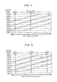
- FIG. 5 is a view that shows voltages that are respectively output from the sensors when the shift lever is operated to shift between an R position and a D position in FIG. 3 ;
- FIG. 6 is a view that shows voltages that are respectively output from the sensors when the shift lever is operated to shift between an N position and the M position in FIG. 3 ;
- FIG. 7 is a relational map that summarizes the relationships between shift positions and voltage values, shown in FIG. 4 to FIG. 6 ;
- FIG. 8 is a flowchart that illustrates a relevant portion of control operations of an electronic control unit shown in FIG. 1 , that is, control operations that enable limp home running on the basis of a shift range and a vehicle speed when two sensors output abnormal values;
- FIG. 9 is a timing chart that illustrates the control operations of the flowchart shown in FIG. 8 ;
- FIG. 10 is a flowchart that illustrates a relevant portion of control operations of the electronic control unit shown in FIG. 1 , that is, control operations that enable limp home running by limiting a driving force when two sensors output abnormal values;
- FIG. 11 is a timing chart that illustrates the control operations of the flowchart shown in FIG. 10 .
- FIG. 1 is a view that illustrates the schematic configuration of a shift control system 10 for a vehicle according to the embodiment.
- the shift control system 10 includes an electronic control unit 20 , a shift operating device 30 , a drive unit 40 , and the like.
- the shift control system 10 functions as the shift-by-wire shift control system 10 that electrically changes the shift range of the drive unit 40 .
- the shift control system 10 according to the aspect of the disclosure is applied to a hybrid vehicle including an engine and an electric motor as driving force sources will be described.
- the shift control system 10 according to the aspect of the disclosure may be applied to a vehicle of another type, such as an engine vehicle and an electric vehicle.
- the electronic control unit 20 corresponds to the electronic control unit according to the aspect of the disclosure.
- the electronic control unit 20 includes a plurality of so-called microcomputers each consisting of a CPU, a ROM, a RAM, input/output interfaces, and the like. Each CPU executes signal processing in accordance with programs prestored in the ROM while utilizing the temporary storage function of the RAM. Thus, the electronic control unit 20 executes drive control, such as hybrid drive control associated with an engine (not shown) or a motor MG provided in the drive unit 40 , control for changing the shift range of the drive unit 40 by using a shift-by-wire system, and the like.
- drive control such as hybrid drive control associated with an engine (not shown) or a motor MG provided in the drive unit 40 , control for changing the shift range of the drive unit 40 by using a shift-by-wire system, and the like.
- a plurality of signals including a shift position signal Pss (shift operating position signal) and a P switch signal Pon, that is, for example, an accelerator operation amount ⁇ acc (%), an output shaft rotation speed Nout (rpm), and the like, are supplied to the electronic control unit 20 .
- the shift position signal Pss is supplied from a position sensor (hereinafter, a Hall IC is the position sensor) for detecting a shift position (shift operating position) of a shift lever 32 (which corresponds to the shift operating unit according to the aspect of the disclosure; hereinafter, the shift operating unit is the shift lever).
- the P switch signal Pon is supplied from a P switch 34 for changing the shift position of the drive unit 40 between a parking position (P range) and a non-P position other than the parking position when operated by a driver.
- the accelerator operation amount ⁇ acc (%) is detected by an accelerator operation amount sensor 52 .
- the output shaft rotation speed Nout (rpm) corresponds to a vehicle speed V (Km/h), and is detected by an output shaft rotation sensor 54 .
- a driving force command signal Se for example, a driving force command signal Se, a shift range signal Psh, a P change control command signal Sp, and the like, are output from the electronic control unit 20 .
- the driving force command signal Se is used to issue a command to operate the engine and the electric motor in the drive unit 40 .
- the shift range signal Psh is used to change the shift range of the drive unit 40 .
- the P change control command signal Sp is used to issue a command to operate a parking lock device 50 .
- FIG. 2 shows an example of the outline of the shift operating device 30 that is operated with the use of the shift lever 32 shown in FIG. 1 .
- the P switch 34 is not shown.
- the shift operating device 30 is, for example, arranged near a driver seat, and includes the momentary shift lever 32 that is operated to a plurality of the shift positions Ps.
- the momentary type is such a type that, when driver's operation of the shift lever 32 is cancelled, the shift lever 32 automatically returns to a middle position (M position) set in advance.
- the shift lever 32 is allowed to be moved in a shift direction parallel to a vehicle longitudinal direction and a select direction parallel to a vehicle width direction along a shift gate 36 .
- the shift lever 32 is allowed to be operated in the shift direction along a first line L 1 and be operated in the shift direction along a second line L 2 parallel to the first line L 1 .
- Three shift positions Ps that is, an R position (R position), a neutral position (N position) and a D position (D position), are set in the first line L 1 .
- R position the shift range is changed to a reverse traveling range.
- N position neutral position
- power transmission is interrupted.
- the shift range is changed to a forward traveling range.
- Two operating positions that is, a middle position (M position) and a B position (B position), are set in the second line L 2 .
- the shift lever 32 is automatically returned to the middle position (M position) after being operated.
- engine brake is generated.
- a select operation of the shift lever 32 is allowed between the M position and the N position.
- a neutral range, a drive range, a reverse range and an engine brake range are control modes of the drive unit 40 , and are respectively established on the basis of a determination as to whether the shift position Ps is the N position, the D position, R position or the B position. Therefore, the neutral range, the drive range, the reverse range and the engine brake range substantially respectively indicate the N position, the D position, the R position and the B position.
- FIG. 3 illustrates the basic hardware configuration of a shift position detector 60 that detects the shift position Ps of the shift lever 32 that is operated in the shift operating device 30 shown in FIG. 2 .
- the shift position detector 60 includes a single magnet 62 and four Hall ICs 64 (hereinafter, IC 1 ), Hall IC 66 (hereinafter, IC 2 ), Hall IC 68 (hereinafter, IC 3 ) and Hall IC 70 (hereinafter, IC 4 ).
- the magnet 62 is provided integrally at the lower end of the shift lever 32 .
- the magnet 62 moves integrally with the shift lever 32 as the shift lever 32 is operated.
- the four Hall ICs 64 , 66 , 68 , 70 are immovably arranged on a substrate (not shown) so as to face the lower face of the magnet 62 . Because the four Hall ICs are arranged below the magnet 62 and are difficult to be visually recognized, the four Hall ICs are shown in FIG. 3 for the sake of convenience such that the relative position of each of the four Hall ICs with respect to the magnet 62 is seen.
- the shift position detector 60 includes the magnet 62 , the Hall IC 64 , the Hall IC 66 , the Hall IC 68 , the Hall IC 70 and the electronic control unit 20 (described later).
- FIG. 3 shows the relative position between the magnet 62 and each Hall IC when the shift lever 32 is operated to one of the shift positions Ps corresponding to FIG. 3 . Therefore, it appears from FIG. 3 that the magnet 62 and the Hall ICs are provided for each shift position Ps. However, actually, the shift operating device 30 is formed of the single magnet 62 and the four Hall ICs, and the magnet 62 is displaced relative to the four Hall ICs as the shift lever 32 is operated.
- the Hall ICs are arranged in line along the shift direction at equal intervals. Therefore, the shift lever 32 is configured to be operable in the shift direction and the select direction. In the shift direction, the shift lever 32 is operated along the direction in which the Hall ICs are arranged. The select direction is perpendicular to the shift direction.
- the magnet 62 provided integrally with the shift lever 32 is formed in a rectangular shape, and is magnetized such that an N pole and an S pole are adjacent to each other in the vertical direction and in the horizontal direction. As a result, the magnet 62 is divided into four magnetic pole areas indicated by the dashed lines in FIG. 3 .
- the top left side and bottom right side of the magnet 62 are N poles
- the top right side and bottom left side of the magnet 62 are S poles.
- the top right area of the magnet 62 is defined as an area A 1 (S pole)
- the top left area of the magnet 62 is defined as an area A 2 (N pole)
- the bottom left area of the magnet 62 is defined as an area A 3 (S pole)
- the bottom right area of the magnet 62 is defined as an area A 4 (N pole).
- the relative position between the magnet 62 and the Hall ICs is the state shown in FIG. 4 .
- the shift lever 32 is placed in the M position (neutral)
- the area A 1 of the magnet 62 faces IC 1 and IC 2
- the area A 4 faces IC 3 and IC 4 .
- the shift lever 32 is shifted from the M position to the B position
- the area A 1 of the magnet 62 faces IC 1 to IC 3
- the area A 4 faces IC 4 as the magnet 62 is relatively moved to the lower side in FIG. 3 with respect to the Hall ICs.
- the area A 2 of the magnet 62 faces IC and the area A 3 faces IC 2 to IC 4 as the magnet 62 is relatively moved to the top right side in FIG. 3 with respect to the Hall ICs.
- the shift lever 32 is operated in the select direction from the M position toward the N position, the area A 2 of the magnet 62 faces IC and IC 2 and the area A 3 faces IC 3 and IC 4 as the magnet 62 is relatively moved to the right side in FIG. 3 with respect to the Hall ICs.
- the area A 2 of the magnet 62 faces IC 1 to IC 3 and the area A 3 faces IC 4 as the magnet 62 is relatively moved to the bottom right side in FIG. 3 with respect to the Hall ICs.
- FIG. 4 shows voltages that are respectively output from the Hall ICs when the shift lever 32 is shifted between the B position and the M position in FIG. 3 .
- the electronic control unit 20 includes an A/D converter that converts an analog voltage that is output from each Hall IC to a digital signal that can be handled by a computer.
- FIG. 5 and the following drawings show voltages converted to digital signals.
- the abscissa axis represents the position of the shift lever 32 when the shift lever 32 is moved in the shift direction along the second line L 2
- the ordinate axis represents voltages that are respectively output from the Hall ICs in the corresponding position.
- voltages that are respectively output from the Hall ICs are positively proportional as the shift lever 32 moves from the B position toward the M position along the second line L 2 .
- a voltage that is output from IC 1 is lower than a voltage that is output from IC 2
- a voltage that is output from IC 2 is lower than a voltage that is output from IC 3
- a voltage that is output from IC 3 is lower than a voltage that is output from IC 4 (IC 1 ⁇ IC 2 ⁇ IC 3 ⁇ IC 4 ).
- the Hall ICs output signal voltages (voltages) based on a relative position (relative distance) to the magnet 62 , and respectively output different voltages for each position of the shift lever 32 .
- a voltage of about 1.00 V is output from IC 1
- a voltage of about 2.00 V is output from IC 2
- a voltage of about 3.00 V is output from IC 3
- a voltage of about 4.00 V is output from IC 4 .
- a voltage of about 0.5 V is output from IC 1
- a voltage of about 1.00 V is output from IC 2
- a voltage of about 2.00 V is output from IC 3
- a voltage of about 3.00 V is output from IC 4 .
- FIG. 5 shows voltage values that are respectively output from the Hall ICs when the shift lever 32 is shifted between the R position and the D position in FIG. 3 .
- voltage values that are respectively output from the Hall ICs are positively proportional as the shift lever 32 moves from the R position toward the D position along the first line L 1 .
- a voltage value that is output from IC 4 is lower than a voltage value that is output from IC 3
- a voltage value that is output from IC 3 is lower than a voltage value that is output from IC 2
- a voltage value that is output from IC 2 is lower than a voltage value that is output from IC 1 (IC 4 ⁇ IC 3 ⁇ IC 2 ⁇ IC 1 ).
- the Hall ICs respectively output different voltage values.
- a voltage of 0.5 V is output from IC 4
- a voltage of about 1.00 V is output from IC 3
- a voltage of about 2.00 V is output from IC 2
- a voltage of about 3.00 V is output from IC 1 .
- a voltage of about 1.00 V is output from IC 4
- a voltage of about 2.00 V is output from IC 3
- a voltage of about 3.00 V is output from IC 2
- a voltage of about 4.00 V is output from IC 1 .
- a voltage of about 2.00 V is output from IC 4
- a voltage of about 3.00 V is output from IC 3
- a voltage of about 4.00 V is output from IC 2
- a voltage of about 4.50 V is output from IC 1 .
- FIG. 6 shows voltages that are respectively output from the Hall ICs when the shift lever 32 is moved in the select direction between the M position and the N position.
- the polarities of the magnet 62 facing the Hall ICs, are inverted, so the relative relation (magnitude relation) among the output voltages of the Hall ICs are inverted due to the inversion of the polarities.
- FIG. 7 is a map of the correspondence relationship between each shift position Ps and voltage values (shift sensor voltages) that are respectively output from the Hall ICs, and corresponds to the relationships between the shift positions Ps and voltage values, shown in FIG. 4 to FIG. 6 .
- the map of FIG. 7 is set and stored in advance.
- the shift position Ps of the shift lever 32 is determined on the basis of the voltage values that are actually respectively output from the Hall ICs by consulting the map.
- the reason why each voltage value has a range for each shift position Ps is that variations in voltage values that are respectively output from the Hall ICs are taken into consideration.
- different voltages are respectively output from the Hall ICs in correspondence with the shift position Ps of the shift lever 32 .
- the shift position Ps is the M position.
- the output of IC 2 falls within the range of a voltage of about 1.6 V to 2.7 V or when the output of IC 3 falls within the range of a voltage of about 2.5 V to 3.6 V or when the output of IC 4 falls within the range of a voltage of about 3.6 V to 4.6 V, it is determined that the shift position Ps is the M position.
- the shift position Ps is a position other than the M position, that is, the B position, the R position, the N position or the D position
- voltages corresponding to the B position, the R position, the N position or the D position are respectively output from IC 1 to IC 4 . Therefore, it is determined whether the shift position Ps is the B position, the R position, the N position or the D position on the basis of voltages that are respectively output from IC 1 to IC 4 .
- the shift position Ps is any one of the M position and the D position on the basis of IC 3
- the shift position Ps is determined as the D position.
- the shift position Ps may also be determined with the shift position detector 60 formed of three Hall ICs by using a method similar to that of the shift position detector 60 including the four Hall ICs according to the present embodiment, that is, on the basis of output voltages of the Hall ICs.
- the shift position Ps is determined on the basis of the remaining three Hall ICs, and limp home running is enabled on the basis of the shift position Ps.
- any one or more of the other Hall ICs are also malfunctioning (hereinafter, referred to as double-sensor malfunction)
- limp home running is enabled by selecting a shift position on the basis of the vehicle speed V of the vehicle and the shift range kept by the drive unit 40 at the time when double-sensor malfunction is determined.
- the electronic control unit 20 includes a first shift position malfunction determination unit 90 , a shift position determination unit 92 and a driving force output command unit 96 as major units.
- the first shift position malfunction determination unit 90 determines whether there is a malfunction in the Hall ICs on the basis of the shift position signals Pss that are output from the shift position detector 60 . Specifically, when there occurs a break or a short circuit, the Hall IC is identified on the basis of the fact that a voltage value that is output from the corresponding Hall IC is 0 V or higher than or equal to 5 V.
- the first shift position malfunction determination unit 90 constantly calculates a differential value (deviation) among the voltages (voltage signals) of the Hall ICs, and determines whether there is a malfunction in the Hall ICs on the basis of whether the difference exceeds a preset allowable value (malfunction deviation).
- the first shift position malfunction determination unit 90 determines the shift position Ps that is the operating position of the shift lever 32 from the Hall ICs, indicates that one malfunctioning Hall IC, and continues limp home running that is normal traveling with notification.
- the shift position determination unit 92 investigates whether the shift position is other than the P position.
- the driving force output command unit 96 keeps the shift position in the P position.
- the driving force output command unit 96 determines whether the output shaft rotation speed Nout, that is, the vehicle speed V, is higher than or equal to a vehicle speed threshold Va set in advance to, for example, about 10 Km/h.
- the vehicle speed threshold Va is, for example, a lower limit value of the vehicle speed at or above which an operation of the shift position to the R position is not accepted during forward traveling.
- the driving force output command unit 96 sets the shift position to the N position since the vehicle speed V has reached a low speed lower than the vehicle speed threshold Va.
- the shift position is kept.
- limp home running is enabled in the case of single-sensor malfunction.
- control operations that hold the shift position or set the shift position to the N position on the basis of the shift position and the vehicle speed at the time when sensor malfunction is determined and that keep the P range when the shift position is the P position are also applicable to the shift position detector 60 formed of three Hall ICs.
- FIG. 8 is a flowchart that illustrates a relevant portion of control operations of the electronic control unit 20 , that is, control operations that enable limp home running even when two or more Hall ICs are malfunctioning. This flowchart is repeatedly executed at an extremely short cycle time of about, for example, several milliseconds to several tens of milliseconds.
- step S 10 (hereinafter, step is omitted) corresponding to the function of the first shift position malfunction determination unit 90 , it is determined whether there is a sensor malfunction, that is, whether there is a malfunction in the Hall ICs.
- the routine is ended.
- affirmative determination is made in S 10 , it is determined in S 20 corresponding to the function of the first shift position malfunction determination unit 90 whether the number of malfunctioning sensors, that is, malfunctioning Hall ICs, is two or more, that is, the number of normal Hall ICs that are not determined to be malfunctioning is two or less.
- the malfunctioning sensors are, for example, determined on the basis of the fact that a voltage difference among the Hall ICs becomes smaller than a lower limit value of a preset normal range or larger than an upper limit value of the preset normal range (malfunction deviation) or the fact that a Hall IC of which the output voltage becomes higher than an intermediate value (2.5 V) of an output voltage range of the Hall ICs in a predetermined shift signal and a Hall IC of which the output voltage becomes lower than the intermediate value (2.5 V) of the output voltage range are not the preset Hall ICs (second malfunction deviation).
- FIG. 9 shows an example of a timing chart in the case where there occurs a malfunction in two Hall ICs and the number of normal Hall ICs that are not determined to be malfunctioning is two.
- the shift lever 32 is operated to the N position while the vehicle is traveling at substantially a constant vehicle speed V (50 Km/h), there occurs a malfunction in shift sensor 1 , that is, IC 1 , at time t 1 after the shift position is changed from the D position to the N position, the shift lever 32 is then immediately operated to the D position, and the shift position is changed from the N position to the D position.
- V 50 Km/h
- the shift position is changed from the D position to the N position.
- the shift lever 32 is operated to the D position; however, the shift position is held in the N position.
- the P switch 34 is operated, and the shift position is changed from the N position to the P position.
- the shift lever 32 is operated to the N position; however, the shift position is held in the P position.
- the shift control system 10 determines the shift position Ps of the shift lever 32 on the basis of output signals from at least three Hall ICs
- the shift range is selected on the basis of the already kept shift position and the vehicle speed V.
- appropriate limp home running is enabled. Specifically, the shift position is held as it is until the vehicle speed V reaches the vehicle speed threshold Va during limp home running, the shift position is changed to the N position at the time when the vehicle speed V becomes lower than the vehicle speed threshold Va.
- the number of normal Hall ICs is two or less, limp home running is ensured until the vehicle speed V reaches the vehicle speed threshold Va.
- the first shift position malfunction determination unit 90 shown in FIG. 1 determines whether there is a double-sensor malfunction, that is, whether two or more Hall ICs are malfunctioning, that is, the number of normal Hall ICs that are not determined to be malfunctioning is two or less.
- the shift position determination unit 92 investigates whether the shift position is other than the P position.
- the driving force output command unit 96 keeps the shift position in the P position.
- the driving force output command unit 96 determines whether the output shaft rotation speed Nout, that is, the vehicle speed V, is higher than or equal to the vehicle speed threshold Va set in advance to, for example, about 10 Km/h. When negative determination is made, the driving force output command unit 96 sets the shift position to the N position on the basis of the fact that the vehicle speed V has reached a low speed lower than the vehicle speed threshold Va. When the vehicle speed V is higher than or equal to the vehicle speed threshold Va, the shift position is kept. These control operations are the same as those of the first embodiment.
- the shift position determination unit 92 determines whether the shift position is other than the N position or the P position.
- the driving force output command unit 96 holds the shift position, and causes the vehicle to perform limp home running with a limited driving force by executing control such that an acceleration ⁇ becomes lower than a preset constant acceleration threshold ⁇ a.
- the acceleration ⁇ is, for example, calculated by differentiating the output shaft rotation speed Nout with respect to time.
- the shift position is a non-drive (non-traveling) position, such as the P position and the N position
- the driving force output command unit 96 holds the shift range.
- control operations that use a method similar to that during traveling when there is a malfunction in one Hall IC while the vehicle is traveling with the four Hall ICs are also applicable to the shift position detector 60 formed of three Hall ICs.
- FIG. 10 is a flowchart that illustrates a relevant portion of control operations of the electronic control unit 20 , that is, alternative control operations that enable limp home running even when two or more Hall ICs are malfunctioning, that is, even when the number of normal Hall ICs that are not determined to be malfunctioning is two or less.
- This flowchart is repeatedly executed at an extremely short cycle time of about, for example, several milliseconds to several tens of milliseconds.
- the flowchart according to the present embodiment in FIG. 10 includes the same steps as S 10 to S 80 of FIG. 8 , but S 10 to S 40 and S 80 are omitted from the flowchart of FIG. 10 .
- S 110 corresponding to the function of the shift position determination unit 92 , it is determined whether the shift position is other than the N position or the P position, that is, other than the non-drive position.
- FIG. 11 shows an example of a timing chart in the case where there occurs a malfunction in two Hall ICs.
- the shift lever 32 is operated to the N position while the vehicle is traveling at substantially a constant vehicle speed V (20 Km/h), there occurs a malfunction in shift sensor 1 , that is, IC 1 , at time t 11 after the shift position is changed from the D position to the N position, the shift lever 32 is then immediately operated to the D position, and the shift position is changed from the N position to the D position.
- the accelerator operation amount becomes 50% as a result of depression of an accelerator pedal for a short time, the acceleration ⁇ also increases in a short time, and the vehicle speed V increases from 20 Km/h to 50 Km/h.
- the accelerator operation amount becomes substantially zero and is gently reducing.
- a double-sensor malfunction that is, there occurs a malfunction also in shift sensor 2 , that is, IC 2
- control that sets the acceleration ⁇ to a value lower than the acceleration threshold ⁇ a is started.
- the accelerator pedal is depressed at an accelerator operation amount of 50%, and the acceleration is kept below the acceleration threshold as that is an upper limit value. Depression of the accelerator pedal at an accelerator operation amount of 50% is kept until time t 14 , and the acceleration ⁇ is kept below the acceleration threshold as through control for limiting the acceleration.
- depression of the accelerator pedal is released, and the vehicle speed V reduces and then indicates a constant low speed.
- the accelerator pedal is depressed again at an accelerator operation amount of 50%; however, the acceleration is limited to a value lower than the acceleration threshold as that is the upper limit value, so just a gentle increase in the vehicle speed V is indicated.
- the shift control system 10 that determines the shift position of the shift lever 32 on the basis of output signals from at least three Hall ICs, when it is determined that the number of normal Hall ICs is two or less, and when the shift position is the N position or the P position, that is, the non-drive position, the shift position is held.
- driving force control is executed such that the acceleration ⁇ becomes lower than the predetermined constant acceleration threshold ⁇ a while the shift position is held.
- the shift operating device 30 has no manual shift mode; however, the disclosure is not limited to this configuration.
- the shift operating device 30 may include an M position or S position in which a manual shift mode for executing manual shift control on the basis of a manual operation of the shift lever 32 is selected.
- the shift lever 32 is of a momentary type; however, the shift lever 32 is not always limited to a momentary type.
- the shift position is set to the N position when the vehicle speed V is lower than the vehicle speed threshold Va, and the shift position is held when the vehicle speed is higher than or equal to the vehicle speed threshold Va.
- the shift position is the P position
- the shift position is held.
- a driving force that is, the acceleration ⁇
- the acceleration ⁇ is limited to a value lower than the acceleration threshold ⁇ a.
- any one of the above-described measures may be used solely or may be used in combination or all the measures may be used.
Landscapes
- Engineering & Computer Science (AREA)
- General Engineering & Computer Science (AREA)
- Mechanical Engineering (AREA)
- Transportation (AREA)
- Chemical & Material Sciences (AREA)
- Combustion & Propulsion (AREA)
- Automation & Control Theory (AREA)
- Control Of Transmission Device (AREA)
- Arrangement Or Mounting Of Control Devices For Change-Speed Gearing (AREA)
Abstract
Description
Claims (4)
Applications Claiming Priority (2)
| Application Number | Priority Date | Filing Date | Title |
|---|---|---|---|
| JP2016244788A JP2018096528A (en) | 2016-12-16 | 2016-12-16 | Shift control device of vehicle |
| JP2016-244788 | 2016-12-16 |
Publications (2)
| Publication Number | Publication Date |
|---|---|
| US20180172144A1 US20180172144A1 (en) | 2018-06-21 |
| US10378646B2 true US10378646B2 (en) | 2019-08-13 |
Family
ID=60327056
Family Applications (1)
| Application Number | Title | Priority Date | Filing Date |
|---|---|---|---|
| US15/794,777 Expired - Fee Related US10378646B2 (en) | 2016-12-16 | 2017-10-26 | Shift control system for vehicle and shift control method for vehicle |
Country Status (4)
| Country | Link |
|---|---|
| US (1) | US10378646B2 (en) |
| EP (1) | EP3336386B1 (en) |
| JP (1) | JP2018096528A (en) |
| CN (1) | CN108204448A (en) |
Families Citing this family (10)
| Publication number | Priority date | Publication date | Assignee | Title |
|---|---|---|---|---|
| CN109185450A (en) * | 2018-08-29 | 2019-01-11 | 汽解放汽车有限公司 | A kind of automatic mechanical transmission shift fault handling method |
| CN110388454A (en) * | 2019-08-12 | 2019-10-29 | 合肥华骏汽车部件有限公司 | A kind of handball assembly transmitted with high and low shift air valve and electronic signal |
| CN112092624B (en) * | 2019-12-27 | 2022-06-14 | 长城汽车股份有限公司 | Monitoring method and device for gear lever position judgment, vehicle control unit and vehicle |
| CN111927946B (en) * | 2020-08-14 | 2022-07-26 | 东风汽车有限公司 | Automobile electronic gear shifter, control method and controller |
| CN111706671B (en) * | 2020-08-18 | 2020-12-11 | 北京航空航天大学 | Vehicle gear shifting driving control method under no speed signal |
| DE102020211371A1 (en) | 2020-09-10 | 2022-03-10 | Ford Global Technologies, Llc | Method of operating a motor vehicle with an e-clutch |
| DE102020126169A1 (en) * | 2020-10-07 | 2022-04-07 | Zf Cv Systems Global Gmbh | Sensor arrangement of an automated manual transmission and method for determining a magnetic interference field |
| CN114508589A (en) * | 2022-04-15 | 2022-05-17 | 盛瑞传动股份有限公司 | Normally-closed fault processing method, device, equipment, medium and vehicle |
| CN115306892A (en) * | 2022-07-15 | 2022-11-08 | 合肥工业大学 | Gear-engaging fault judging system of double-flow transmission vehicle |
| CN115750768A (en) * | 2022-10-31 | 2023-03-07 | 重庆长安汽车股份有限公司 | Vehicle gear shifting control method, vehicle control method, system, device and medium |
Citations (10)
| Publication number | Priority date | Publication date | Assignee | Title |
|---|---|---|---|---|
| JP2001289084A (en) | 2000-03-16 | 2001-10-19 | Bayerische Motoren Werke Ag | Motor vehicle with transmission controlled by electronic transmission unit |
| US20040162661A1 (en) | 2003-02-18 | 2004-08-19 | Nissan Motor Co., Ltd | Range selection control device of automatic transmission |
| US20050126322A1 (en) * | 2003-12-10 | 2005-06-16 | Denso Corporation | Automatic transmission control system with shift lever position sensor |
| JP2010120394A (en) | 2008-11-17 | 2010-06-03 | Mannoh Co Ltd | Shift position detection device |
| JP2010151302A (en) | 2008-11-28 | 2010-07-08 | Aisin Aw Co Ltd | Power transmission device |
| US20110202231A1 (en) * | 2009-02-27 | 2011-08-18 | Toyota Jidosha Kabushiki Kaisha | Vehicle control device |
| JP2011163782A (en) | 2010-02-04 | 2011-08-25 | Tokai Rika Co Ltd | Device for detection of operating position |
| WO2013179997A1 (en) | 2012-05-30 | 2013-12-05 | アルプス電気株式会社 | Position detection device and shift position detection device |
| WO2016020739A1 (en) | 2014-08-06 | 2016-02-11 | Toyota Jidosha Kabushiki Kaisha | Shift position detecting device for vehicle and shift control device for vehicle |
| US9410616B2 (en) * | 2014-12-02 | 2016-08-09 | Toyota Jidosha Kabushiki Kaisha | Shift lever position determination device for vehicle |
Family Cites Families (1)
| Publication number | Priority date | Publication date | Assignee | Title |
|---|---|---|---|---|
| WO2013005294A1 (en) * | 2011-07-05 | 2013-01-10 | トヨタ自動車株式会社 | Shift sensor and vehicle provided with said shift sensor |
-
2016
- 2016-12-16 JP JP2016244788A patent/JP2018096528A/en active Pending
-
2017
- 2017-10-26 US US15/794,777 patent/US10378646B2/en not_active Expired - Fee Related
- 2017-11-02 EP EP17199783.6A patent/EP3336386B1/en not_active Not-in-force
- 2017-11-07 CN CN201711086143.9A patent/CN108204448A/en active Pending
Patent Citations (15)
| Publication number | Priority date | Publication date | Assignee | Title |
|---|---|---|---|---|
| JP2001289084A (en) | 2000-03-16 | 2001-10-19 | Bayerische Motoren Werke Ag | Motor vehicle with transmission controlled by electronic transmission unit |
| US20010039232A1 (en) | 2000-03-16 | 2001-11-08 | Rudolf Ehrmaier | Motor vehicle having a transmission controlled by an electronic transmission unit |
| US20040162661A1 (en) | 2003-02-18 | 2004-08-19 | Nissan Motor Co., Ltd | Range selection control device of automatic transmission |
| CN1530571A (en) | 2003-02-18 | 2004-09-22 | �ղ��Զ�����ʽ���� | Gearing controller of automatic gear |
| US20050126322A1 (en) * | 2003-12-10 | 2005-06-16 | Denso Corporation | Automatic transmission control system with shift lever position sensor |
| US7584681B2 (en) * | 2003-12-10 | 2009-09-08 | Denso Corporation | Automatic transmission control system |
| JP2010120394A (en) | 2008-11-17 | 2010-06-03 | Mannoh Co Ltd | Shift position detection device |
| JP2010151302A (en) | 2008-11-28 | 2010-07-08 | Aisin Aw Co Ltd | Power transmission device |
| US20110202231A1 (en) * | 2009-02-27 | 2011-08-18 | Toyota Jidosha Kabushiki Kaisha | Vehicle control device |
| JP2011163782A (en) | 2010-02-04 | 2011-08-25 | Tokai Rika Co Ltd | Device for detection of operating position |
| WO2013179997A1 (en) | 2012-05-30 | 2013-12-05 | アルプス電気株式会社 | Position detection device and shift position detection device |
| WO2016020739A1 (en) | 2014-08-06 | 2016-02-11 | Toyota Jidosha Kabushiki Kaisha | Shift position detecting device for vehicle and shift control device for vehicle |
| JP2016038002A (en) | 2014-08-06 | 2016-03-22 | トヨタ自動車株式会社 | Vehicle shift position detection device and vehicle shift control device |
| US10180184B2 (en) * | 2014-08-06 | 2019-01-15 | Toyota Jidosha Kabushiki Kaisha | Shift position detecting device for vehicle and shift control device for vehicle |
| US9410616B2 (en) * | 2014-12-02 | 2016-08-09 | Toyota Jidosha Kabushiki Kaisha | Shift lever position determination device for vehicle |
Also Published As
| Publication number | Publication date |
|---|---|
| EP3336386A1 (en) | 2018-06-20 |
| EP3336386B1 (en) | 2019-08-07 |
| JP2018096528A (en) | 2018-06-21 |
| CN108204448A (en) | 2018-06-26 |
| US20180172144A1 (en) | 2018-06-21 |
Similar Documents
| Publication | Publication Date | Title |
|---|---|---|
| US10378646B2 (en) | Shift control system for vehicle and shift control method for vehicle | |
| US8914185B2 (en) | Vehicle control device | |
| US10180184B2 (en) | Shift position detecting device for vehicle and shift control device for vehicle | |
| CN108331917B (en) | Shift control device for vehicle | |
| EP3372440A1 (en) | Regenerative braking control device for electric vehicle | |
| US8862303B2 (en) | Industrial vehicle | |
| JP5071422B2 (en) | Vehicle shift control device | |
| US10458356B2 (en) | Vehicle control apparatus | |
| US10571019B2 (en) | Control system for vehicle | |
| JP2014156140A (en) | Mis-operation controller for accelerator pedal | |
| JP5713113B2 (en) | Vehicle control device | |
| KR100836296B1 (en) | trouble management method for shift position sensors of a vehicle | |
| JP2017153188A (en) | Vehicle control system | |
| CN114126911B (en) | Control device and control method for vehicle | |
| JP6627649B2 (en) | Control device for vehicle shift position detection device | |
| SE505276C2 (en) | Arrangement for eliminating the rest position of a manually actuated actuator of a motor vehicle | |
| JP2005113830A (en) | Power system | |
| CN117955366A (en) | Method for preventing accidental start of work machine | |
| JP2004175220A (en) | Engine control device |
Legal Events
| Date | Code | Title | Description |
|---|---|---|---|
| AS | Assignment |
Owner name: TOYOTA JIDOSHA KABUSHIKI KAISHA, JAPAN Free format text: ASSIGNMENT OF ASSIGNORS INTEREST;ASSIGNORS:YUMA, TAKASHI;UENO, KOKI;TATENO, MASATO;AND OTHERS;SIGNING DATES FROM 20171003 TO 20171004;REEL/FRAME:044636/0552 |
|
| FEPP | Fee payment procedure |
Free format text: ENTITY STATUS SET TO UNDISCOUNTED (ORIGINAL EVENT CODE: BIG.); ENTITY STATUS OF PATENT OWNER: LARGE ENTITY |
|
| STPP | Information on status: patent application and granting procedure in general |
Free format text: NON FINAL ACTION MAILED |
|
| STPP | Information on status: patent application and granting procedure in general |
Free format text: NOTICE OF ALLOWANCE MAILED -- APPLICATION RECEIVED IN OFFICE OF PUBLICATIONS |
|
| ZAAA | Notice of allowance and fees due |
Free format text: ORIGINAL CODE: NOA |
|
| ZAAB | Notice of allowance mailed |
Free format text: ORIGINAL CODE: MN/=. |
|
| STCF | Information on status: patent grant |
Free format text: PATENTED CASE |
|
| FEPP | Fee payment procedure |
Free format text: MAINTENANCE FEE REMINDER MAILED (ORIGINAL EVENT CODE: REM.); ENTITY STATUS OF PATENT OWNER: LARGE ENTITY |
|
| LAPS | Lapse for failure to pay maintenance fees |
Free format text: PATENT EXPIRED FOR FAILURE TO PAY MAINTENANCE FEES (ORIGINAL EVENT CODE: EXP.); ENTITY STATUS OF PATENT OWNER: LARGE ENTITY |
|
| STCH | Information on status: patent discontinuation |
Free format text: PATENT EXPIRED DUE TO NONPAYMENT OF MAINTENANCE FEES UNDER 37 CFR 1.362 |
|
| FP | Lapsed due to failure to pay maintenance fee |
Effective date: 20230813 |