US10356287B2 - Optical scanning apparatus and method of controlling optical scanning apparatus - Google Patents
Optical scanning apparatus and method of controlling optical scanning apparatus Download PDFInfo
- Publication number
- US10356287B2 US10356287B2 US15/910,088 US201815910088A US10356287B2 US 10356287 B2 US10356287 B2 US 10356287B2 US 201815910088 A US201815910088 A US 201815910088A US 10356287 B2 US10356287 B2 US 10356287B2
- Authority
- US
- United States
- Prior art keywords
- optical fiber
- actuator
- distal end
- subject
- illumination light
- Prior art date
- Legal status (The legal status is an assumption and is not a legal conclusion. Google has not performed a legal analysis and makes no representation as to the accuracy of the status listed.)
- Active
Links
Images


Classifications
-
- H—ELECTRICITY
- H04—ELECTRIC COMMUNICATION TECHNIQUE
- H04N—PICTORIAL COMMUNICATION, e.g. TELEVISION
- H04N3/00—Scanning details of television systems; Combination thereof with generation of supply voltages
- H04N3/10—Scanning details of television systems; Combination thereof with generation of supply voltages by means not exclusively optical-mechanical
- H04N3/30—Scanning details of television systems; Combination thereof with generation of supply voltages by means not exclusively optical-mechanical otherwise than with constant velocity or otherwise than in pattern formed by unidirectional, straight, substantially horizontal or vertical lines
- H04N3/34—Elemental scanning area oscillated rapidly in direction transverse to main scanning direction
-
- A—HUMAN NECESSITIES
- A61—MEDICAL OR VETERINARY SCIENCE; HYGIENE
- A61B—DIAGNOSIS; SURGERY; IDENTIFICATION
- A61B1/00—Instruments for performing medical examinations of the interior of cavities or tubes of the body by visual or photographical inspection, e.g. endoscopes; Illuminating arrangements therefor
- A61B1/00002—Operational features of endoscopes
- A61B1/00004—Operational features of endoscopes characterised by electronic signal processing
- A61B1/00006—Operational features of endoscopes characterised by electronic signal processing of control signals
-
- A—HUMAN NECESSITIES
- A61—MEDICAL OR VETERINARY SCIENCE; HYGIENE
- A61B—DIAGNOSIS; SURGERY; IDENTIFICATION
- A61B1/00—Instruments for performing medical examinations of the interior of cavities or tubes of the body by visual or photographical inspection, e.g. endoscopes; Illuminating arrangements therefor
- A61B1/00163—Optical arrangements
- A61B1/00172—Optical arrangements with means for scanning
-
- A—HUMAN NECESSITIES
- A61—MEDICAL OR VETERINARY SCIENCE; HYGIENE
- A61B—DIAGNOSIS; SURGERY; IDENTIFICATION
- A61B1/00—Instruments for performing medical examinations of the interior of cavities or tubes of the body by visual or photographical inspection, e.g. endoscopes; Illuminating arrangements therefor
- A61B1/04—Instruments for performing medical examinations of the interior of cavities or tubes of the body by visual or photographical inspection, e.g. endoscopes; Illuminating arrangements therefor combined with photographic or television appliances
- A61B1/043—Instruments for performing medical examinations of the interior of cavities or tubes of the body by visual or photographical inspection, e.g. endoscopes; Illuminating arrangements therefor combined with photographic or television appliances for fluorescence imaging
-
- A—HUMAN NECESSITIES
- A61—MEDICAL OR VETERINARY SCIENCE; HYGIENE
- A61B—DIAGNOSIS; SURGERY; IDENTIFICATION
- A61B1/00—Instruments for performing medical examinations of the interior of cavities or tubes of the body by visual or photographical inspection, e.g. endoscopes; Illuminating arrangements therefor
- A61B1/06—Instruments for performing medical examinations of the interior of cavities or tubes of the body by visual or photographical inspection, e.g. endoscopes; Illuminating arrangements therefor with illuminating arrangements
- A61B1/07—Instruments for performing medical examinations of the interior of cavities or tubes of the body by visual or photographical inspection, e.g. endoscopes; Illuminating arrangements therefor with illuminating arrangements using light-conductive means, e.g. optical fibres
-
- G—PHYSICS
- G02—OPTICS
- G02B—OPTICAL ELEMENTS, SYSTEMS OR APPARATUS
- G02B23/00—Telescopes, e.g. binoculars; Periscopes; Instruments for viewing the inside of hollow bodies; Viewfinders; Optical aiming or sighting devices
- G02B23/24—Instruments or systems for viewing the inside of hollow bodies, e.g. fibrescopes
- G02B23/2407—Optical details
- G02B23/2461—Illumination
- G02B23/2469—Illumination using optical fibres
-
- G—PHYSICS
- G02—OPTICS
- G02B—OPTICAL ELEMENTS, SYSTEMS OR APPARATUS
- G02B23/00—Telescopes, e.g. binoculars; Periscopes; Instruments for viewing the inside of hollow bodies; Viewfinders; Optical aiming or sighting devices
- G02B23/24—Instruments or systems for viewing the inside of hollow bodies, e.g. fibrescopes
- G02B23/26—Instruments or systems for viewing the inside of hollow bodies, e.g. fibrescopes using light guides
-
- G—PHYSICS
- G02—OPTICS
- G02B—OPTICAL ELEMENTS, SYSTEMS OR APPARATUS
- G02B26/00—Optical devices or arrangements for the control of light using movable or deformable optical elements
- G02B26/08—Optical devices or arrangements for the control of light using movable or deformable optical elements for controlling the direction of light
- G02B26/10—Scanning systems
- G02B26/103—Scanning systems having movable or deformable optical fibres, light guides or waveguides as scanning elements
-
- H—ELECTRICITY
- H04—ELECTRIC COMMUNICATION TECHNIQUE
- H04N—PICTORIAL COMMUNICATION, e.g. TELEVISION
- H04N23/00—Cameras or camera modules comprising electronic image sensors; Control thereof
- H04N23/50—Constructional details
- H04N23/555—Constructional details for picking-up images in sites, inaccessible due to their dimensions or hazardous conditions, e.g. endoscopes or borescopes
Definitions
- the present invention relates to an optical scanning apparatus and a method of controlling the optical scanning apparatus.
- a known scanning endoscope apparatus in the related art scans a laser beam along a spiral path (for example, see Patent Literature 1).
- the resolution of images captured by the scanning endoscope apparatus depends on the distance between scanning lines of the laser beam (the scanning-line pitch).
- the resolution of the images is increased by doubling the spiral number (number of circulations) of the laser beam to halve the scanning-line pitch.
- An optical scanning apparatus includes: an optical fiber that emits illumination light from a distal end thereof toward a subject; an actuator that oscillates the distal end of the optical fiber; and a controller that controls the actuator so as to two-dimensionally scan the illumination light emitted from the distal end of the optical fiber on the subject.
- the controller controls the actuator so as to satisfy Conditional Expression (1) below: P 1 ⁇ 0.5 ⁇ D, (1) where D is a spot diameter of the illumination light on the subject, and P1 is a scanning-line pitch of the illumination light on the subject.
- An optical scanning apparatus includes: an optical fiber that emits illumination light from a distal end thereof toward a subject; an actuator that oscillates the distal end of the optical fiber; a controller that controls the actuator so as to two-dimensionally scan the illumination light emitted from the distal end of the optical fiber on the subject; and a light detecting unit that detects observation light generated in the subject as a result of the subject being irradiated with the illumination light.
- the controller controls the light detecting unit so as to satisfy Conditional Expression (2) below: P 2 ⁇ 0.5 ⁇ D, (2) where D is a spot diameter of the illumination light on the subject, and P2 is a sampling pitch of the observation light on the subject.
- a third aspect of the present invention provides a method of controlling an optical scanning apparatus that spirally scans light emitted from a distal end of an optical fiber on a subject, wherein, in a control step in which an actuator that oscillates the distal end of the optical fiber so as to two-dimensionally scan the illumination light emitted from the distal end of the optical fiber on the subject is controlled, the actuator is controlled so as to satisfy Conditional Expression (1) below: P 1 ⁇ 0.5 ⁇ D, (1) where D is a spot diameter of the illumination light on the subject, and P1 is a scanning-line pitch of the illumination light on the subject.
- FIG. 1 shows the overall configuration of an optical scanning apparatus and a scanning endoscope system according to an embodiment of the present invention.
- FIG. 2 is a diagram showing a scanning path, on a subject, of illumination light scanned by the optical scanning apparatus in FIG. 1 .
- FIG. 3A is a diagram for explaining the relationship between the spot diameter of the illumination light and the resolution.
- FIG. 3B is a diagram showing the distribution of the intensity of reflected light obtained when the spot diameter of the illumination light and the pitch of a stripe pattern in a chart are equal.
- FIG. 4 is a diagram showing the change in the intensity of the illumination light at a cross section of the beam.
- FIG. 5 is a graph showing the relationship between the ratio of the pitch of the chart and the spot diameter of the illumination light (horizontal axis), and the contrast of the intensity of the reflected light (vertical axis).
- FIG. 6 is a diagram for explaining Conditional Expression (3).
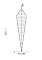
- FIG. 7 is a diagram showing a time-series change of the amplitude of the distal end of an optical fiber, the change occurring along a linear envelope.
- FIG. 8 is a diagram showing a time-series change of the amplitude of the distal end of the optical fiber, the change occurring along a sinusoidal envelope.
- FIG. 9 is a diagram for explaining Conditional Expression (9).
- FIG. 10 is a diagram showing a double telecentric scanning lens system, serving as a modification of the scanning lens system of the optical scanning apparatus in FIG. 1 .
- FIG. 11 is a graph showing a function g(Z) for explaining Conditional Expressions (3) and (4).
- the optical scanning apparatus 1 As shown in FIG. 1 , the optical scanning apparatus 1 according to this embodiment is equipped in a scanning endoscope system 100 .
- the scanning endoscope system 100 includes a light source 2 , the optical scanning apparatus 1 that scans illumination light L output from the light source 2 over a subject A and detects observation light L′ generated in the subject A, an image generating unit 3 that generates a two-dimensional image of the subject A based on the intensity of the observation light L′ detected by the optical scanning apparatus 1 , and a display 4 that displays the image generated by the image generating unit 3 .
- the observation light L′ is reflected light, scattered light, or fluorescence from the subject A.
- Denoted by reference sign 20 is an elongated insertion section insertable into the body
- denoted by reference sign 30 is a control unit body connected to the proximal end of the insertion section 20 .
- the light source 2 is a laser light source that outputs a laser beam, serving as the illumination light L.
- the optical scanning apparatus 1 includes an optical scanning unit 5 that scans the illumination light L from the light source 2 , a signal generating unit 6 that generates a driving signal for driving the optical scanning unit 5 , a light detecting unit 7 that detects the observation light L′ generated in the subject A irradiated with the illumination light L, and a controller 8 for controlling the optical scanning unit 5 , the signal generating unit 6 , and the light detecting unit 7 .
- the optical scanning unit 5 includes: an optical fiber 9 that guides the illumination light L emitted from the light source 2 and entering from the proximal end thereof and emits the light from a distal end 9 a thereof; an actuator 10 that oscillates the distal end 9 a of the optical fiber 9 in the radial direction of the optical fiber 9 ; and a scanning lens system 11 .
- the optical fiber 9 is disposed in the insertion section 20 along the longitudinal direction thereof.
- the actuator 10 is of a piezoelectric type and is provided on the outer circumferential surface of the optical fiber 9 , at a position away from the distal end 9 a toward the proximal end.
- the actuator 10 supports one end of the distal end portion of the optical fiber 9 .
- the actuator 10 excites an oscillation in the distal end portion of the optical fiber 9 based on a driving signal supplied from the signal generating unit 6 to spirally oscillate the distal end 9 a along a spiral path.
- the illumination light L emitted from the distal end 9 a of the optical fiber 9 is spirally scanned along a spiral scanning path B over the subject A, which is opposite the distal end of the insertion section 20 .
- the actuator 10 includes an X-direction piezoelectric element (not shown) and a Y-direction piezoelectric element (not shown) that oscillates the distal end portion of the optical fiber 9 in the X direction and the Y direction via, for example, a ferrule.
- the X direction and the Y direction are perpendicular to the longitudinal direction of the optical fiber 9 and are perpendicular to each other.
- the piezoelectric elements are each supplied with a high-frequency signal (continuous-wave signal), serving as a driving signal, in which gradual increase and decrease in the amplitude are repeated.
- the X-direction and Y-direction piezoelectric elements having received the driving signals generate, in the distal end portion of the optical fiber 9 , bending vibrations in the X direction and the Y direction, respectively, having substantially the same frequencies as the frequencies of the driving signals and having amplitudes that vary with changes in the amplitudes of the driving signals.
- the phase of the driving signal applied to the X-direction piezoelectric element and the phase of the driving signal applied to the Y-direction piezoelectric element are shifted from each other by substantially ⁇ /2.
- the application of these driving signals to the piezoelectric elements spirally oscillates the distal end 9 a of the optical fiber 9 .
- the actuator 10 may be of an electromagnetic type in which a magnet attached to the optical fiber 9 is oscillated by means of an electromagnetic coil, or of another type, instead of the piezoelectric type.
- the scanning lens system 11 is disposed in front of the distal end 9 a of the optical fiber 9 .
- the scanning lens system 11 has a positive refractive power and focuses the illumination light L entering from the distal end 9 a of the optical fiber 9 .
- the signal generating unit 6 generates a driving signal having a frequency and amplitude specified by the control signal received from the controller 8 and supplies the driving signal to the actuator 10 .
- the light detecting unit 7 includes: a light-receiving optical fiber 12 that receives, at the distal end thereof, observation light L′ (e.g., reflected light of the illumination light L, light scattered by the subject A, or fluorescence excited by the illumination light L) generated by the subject A; a photodetector 13 , such as a photomultiplier, that detects the observation light L′ received by the light-receiving optical fiber 12 ; and an AD converter 14 that performs analog-to-digital (AD) conversion of the electric signal output from the photodetector 13 .
- observation light L′ e.g., reflected light of the illumination light L, light scattered by the subject A, or fluorescence excited by the illumination light L
- a photodetector 13 such as a photomultiplier
- the distal end of the light-receiving optical fiber 12 is disposed at the distal end surface of the insertion section 20 , and the proximal end of the light-receiving optical fiber 12 is connected to the photodetector 13 .
- the photodetector 13 photoelectrically converts the observation light L′ entering from the light-receiving optical fiber 12 to generate an electric signal corresponding to the intensity of the observation light L′ and outputs the generated electric signal to the AD converter 14 .
- the AD converter 14 samples the electric signal input from the photodetector 13 in synchronization with a sampling signal received from the controller 8 and converts the analog signal to a digital signal, thus obtaining a digital value representing the intensity of the observation light L′.
- the AD converter 14 transmits the obtained digital value to the image generating unit 3 .
- the controller 8 generates a control signal and transmits the control signal to the signal generating unit 6 .
- the controller 8 sets a frequency and an amplitude of the driving signal at which the diameter D of the spot (spot diameter) of the illumination light L on the subject A and the scanning-line pitch P1 of the illumination light L satisfy Conditional Expressions (1) and (1)′, and generates a control signal for generating the driving signal having the set frequency and amplitude.
- Conditional Expressions (1) and (1)′ relate to the resolution in the radial direction of the scanning path B: P 1 ⁇ 0.5 ⁇ D. (1) 0.25 ⁇ D ⁇ P 1. (1)′
- the scanning-line pitch P1 is the distance, in the radial direction, between two substantially circular scanning lines that are adjacent to each other in the radial direction (a direction intersecting the illumination-light scanning direction L) on the spiral scanning path B on the subject A.
- the scanning-line pitch P1 is determined by the frequency of the oscillation of the distal end of the optical fiber 9 and the rate of change of the amplitude.
- the controller 8 can control the actuator 10 such that the scanning-line pitch P1 satisfies Conditional Expressions (1) and (1)′.
- the controller 8 generates a sampling signal having a certain sampling frequency and transmits the sampling signal to the AD converter 14 .
- the controller 8 generates a sampling signal having a sampling frequency with which the spot diameter D of the illumination light L on the subject A and the sampling pitch P2 satisfy Conditional Expressions (2) and (2)′.
- Conditional Expressions (2) and (2)′ relate to the resolution in the circumferential direction of the scanning path B. P 2 ⁇ 0.5 ⁇ D (2) 0.25 ⁇ D ⁇ P 2 (2)′
- the sampling pitch P2 is the distance between sampling points (the positions irradiated with the illumination light L when the electric signal of the observation light L′ is sampled by the AD converter 14 ) that are adjacent to each other in the circumferential direction (the scanning direction of the illumination light L) on the scanning path B.
- the sampling pitch P2 is determined by the sampling frequency with which the electric signal is sampled by the AD converter 14 .
- the controller 8 can control the AD converter 14 such that the sampling pitch P2 satisfies Conditional Expressions (2) and (2)′.
- the driving signal is assumed to have a waveform having sinusoidal envelopes, as shown in, for example, FIG. 8 .
- the controller 8 changes the frequency of an amplitude modulating wave while fixing the driving frequency fd, the number of scanning circulations N per frame changes, and the scanning pitch P1 in the radial direction also changes. Meanwhile, also if the controller 8 changes the driving frequency fd while fixing the frequency of the amplitude modulating wave, the number of scanning circulations N changes, thus making it possible to change the scanning pitch P1 in the radial direction.
- the controller 8 changes the amplitude of the driving signal fd while fixing the number of scanning circulations N, the size of the scanning area changes, and, also in this case, the scanning pitch P1 in the radial direction can be changed. Furthermore, if the controller 8 changes the driving frequency fd while fixing the sampling frequency fs of the photodetector 13 , the scanning speed in the circumferential direction changes, and thus, the sampling pitch P2 in the circumferential direction can be changed.
- the pitches P1 and P2 on the subject can be controlled.
- the spot diameter D of the illumination light L on the subject A is determined by the optical properties of optical systems, such as the optical fiber 9 and the scanning lens system 11 , through which the illumination light L passes, and the distance between the scanning lens system 11 and the subject A. Because the distance between the scanning lens system 11 and the subject A is substantially uniform in observation using the scanning endoscope system 100 , the spot diameter D can be regarded as a fixed value.
- the controller 8 calculates, from the control signal, the position on the subject A irradiated with the illumination light L by the optical scanning unit 5 when the AD converter 14 samples the electric signal according to the sampling signal, and transmits information about the calculated irradiation position to the image generating unit 3 .
- the image generating unit 3 generates a two-dimensional image of the subject A by associating the digital value received from the AD converter 14 with the information about the irradiation position of the observation light L′ received from the controller 8 .
- the image generating unit 3 transmits the generated image to the display 4 for display.
- the image generating unit 3 and the controller 8 are formed of, for example, a general-purpose or dedicated computer. More specifically, the computer includes: a central processing unit (CPU); a main storage device, such as a RAM; and a sub-storage device, such as a hard disk that stores a control program and an image generating program.
- the CPU realizes the processing by the controller 8 .
- the CPU realizes the above-described processing by the image generating unit 3 according to the image program.
- the insertion section 20 is inserted into the body, and the distal end of the insertion section 20 is made to face the living tissue, serving as the subject A.
- the illumination light L is radiated from the distal end 9 a of the optical fiber 9 on the subject A.
- the actuator 10 spirally oscillates the distal end 9 a of the optical fiber 9 , so that the illumination light L is spirally scanned on the subject A.
- the observation light L′ generated at the irradiation position of the illumination light L is received by the distal end of the light-receiving optical fiber 12 , and the photodetector 13 detects the intensity of the observation light L′. Then, the AD converter 14 obtains the digital value of the intensity of the observation light L′. The obtained digital value is transmitted to the image generating unit 3 .
- the image generating unit 3 generates an image by storing the digital value received from the AD converter 14 and the irradiation position of the illumination light L received from the controller 8 in an associated manner. The formed image is displayed on the display 4 .
- the relationship between the spot diameter D of the illumination light L and the pitches i.e., the scanning-line pitch P1 and sampling pitch P2, will be described.
- the spot diameter D is the Gaussian spot diameter when the illumination light L is assumed to have an intensity according to the Gaussian distribution.
- a Gaussian spot diameter is defined as the beam width at which the intensity is 1/e 2 of the maximum intensity.
- FIG. 3B shows the intensity of the reflected light of the illumination light L obtained from the chart when the spot diameter D and the pitch S are equal (that is, the spatial frequency of the chart is 1/D).
- FIG. 3B shows changes in the intensity of the reflected light obtained when the illumination light L is scanned in the direction of the arrow in the area enclosed by a rectangle in FIG. 3A .
- the vertical axis in FIG. 3B shows the intensity of the reflected light whose maximum intensity is normalized as 1.
- the intensity of the reflected light varies with the irradiation position of the illumination light L, and the contrast of the intensity of the reflected light is expressed by (Imax ⁇ Imin)/(Imax+Imin). Imax is the maximum value of the intensity of the reflected light, and Imin is the minimum value of the intensity of the reflected light.
- the contrast is calculated to be approximately 30%.
- FIG. 5 shows the calculation result of the contrast of the intensity of the reflected light when the proportion of the pitch S in the spot diameter D (S/D) is changed.
- the contrast is 74%
- the stripe pattern of the chart can be fully resolved.
- the contrast is 1% or less
- the stripe pattern of the chart cannot be resolved. If the lower limit of the contrast required to resolving the stripe pattern of the chart is set to 30%, the resolution limit is reached when the pitch S is equal to the spot diameter D (that is, when the spatial frequency of the chart is 1/D).
- the scanning-line pitch P1 needs to be 0.5D or less (the spatial frequency needs to be 2/D or more), based on the sampling theorem (sampling theorem).
- the scanning-line pitch P1 is set to 0.5D or less, a pattern having a minimum radial pitch that is theoretically resolvable with the illumination light L having the spot diameter D can be reproduced with 30% contrast in an image.
- the sampling pitch P2 for the same reason as the scanning-line pitch P1, by controlling the sampling pitch P2 to be from 0.25D to 0.5D, a pattern having a minimum pitch in the circumferential direction of the scanning path B that is theoretically resolvable with the illumination light L having the spot diameter D can be reproduced with 30% contrast in an image.
- the resolution of the image obtained with the optical scanning apparatus 1 depends not only on the scanning-line pitch P1 and the sampling pitch P2, but also on the relationship between the spot diameter D of the irradiation light L and the pitches P1 and P2.
- the actuator 10 is controlled such that the scanning-line pitch P1 satisfies Conditional Expressions (1) and (1)′ with respect to the spot diameter D
- the AD converter 14 is controlled such that the sampling pitch P2 satisfies Conditional Expressions (2) and (2)′ with respect to the spot diameter D.
- the controller 8 may control the actuator 10 so as to additionally satisfy Conditional Expression (3).
- Conditional Expression (3) Pf is the scanning pitch of the distal end 9 a of the optical fiber 9
- d is the core diameter of the optical fiber 9 .
- P 1 D/d ⁇ Pf (3)
- Conditional Expression (3) can also be expressed as below: Pf ⁇ 0.5 ⁇ d. (3)
- the scanning pitch Pf is a pitch (the distance between two points, which corresponds to two sampling points adjacent to each other in the radial direction or the circumferential direction on the oscillation path) of the distal end 9 a of the optical fiber 9 in the radial direction or the circumferential direction.
- FIG. 6 is a diagram for explaining Conditional Expression (3).
- a wide-angle lens system having a large angle-of-view is used as the scanning lens system 11 of the optical scanning apparatus 1 for the scanning endoscope system 100 .
- the distal end portion of the optical fiber 9 oscillated by the actuator 10 performs bending vibration.
- the amplitude of the distal end 9 a of the optical fiber 9 is smaller than the length of the distal end portion of the optical fiber 9 , the displacement of the distal end portion of the optical fiber 9 caused by the oscillation is regarded as a parallel movement in the radial direction, as shown in FIG. 6 . Accordingly, the principal ray of the illumination light L incident on the scanning lens system 11 on the optical fiber 9 side of the scanning lens system 11 can be approximated as telecentric.
- the amplitude h of the distal end 9 a of the optical fiber 9 and the amplitude H of the illumination light L on the subject A are expressed by the expressions below by using the scanning angle ⁇ of the illumination light L.
- F is the focal distance of the scanning lens system 11
- the object distance Z is the distance between the rear focal position of the scanning lens system 11 and the subject A.
- FIG. 11 shows the result of calculating a function g(Z).
- the distal end 9 a of the optical fiber 9 is located at the front focal position of the scanning lens system 11 .
- the value of the function g(Z) is greater than the core diameter d of the optical fiber 9 . Accordingly, Expression (3) is derived from Expression (3)′′.
- the beam waist diameter ⁇ 0 4 ⁇ F/ ⁇ d where ⁇ is the wavelength of the laser beam.
- D 0 ⁇ (4 ⁇ F/ ⁇ d ) 2 +( d/F ) 2 ⁇ Z 2 ⁇ 1/2 .
- g ( Z) f ⁇ (4 ⁇ f/ ⁇ dz ) 2 +( d/f ) 2 ⁇ 1/2
- the optimum pitches P1, P2, and Pf depend also on the core diameter d of the optical fiber 9 .
- the optical scanning apparatus 1 can more effectively exert the potential resolving power thereof, and it is possible to capture higher resolution images.
- N is the number of scanning cycles of the illumination light L on the scanning path B (the number of circles when the scanning path B is approximated as a collection of concentric circles), and hmax is the maximum amplitude of the distal end 9 a of the optical fiber 9 .
- Pf h max/ N (5) Pf ⁇ / 2 ⁇ h max/ N (7)
- the shape of the envelopes of the driving signal can be linear or sinusoidal.
- Conditional Expression (5) is derived because the scanning pitch Pf in the spiral oscillation path of the distal end 9 a of the optical fiber 9 is uniform.
- the controller 8 controls the actuator 10 so as to satisfy Conditional Expression (7).
- the amplitude of the distal end 9 a of the optical fiber 9 is half of the maximum amplitude, the scanning pitch Pf is maximum, and the resolution is minimum.
- the maximum scanning pitch Pf is derived as follows.
- fd is the oscillation frequency of the distal end 9 a of the optical fiber 9
- dY/dt ⁇ h max ⁇ f 0 ⁇ sin(2 ⁇ f 0 t ).
- controller 8 control the actuator 10 and the photodetector 13 so as to additionally satisfy Conditional Expression (9): Pf ⁇ 2 ⁇ h max ⁇ sin( ⁇ fd/fs ). (9)
- Conditional Expression (9) defines the condition for obtaining a high resolution even on the radially outermost scanning line.
- the illumination light L is spirally scanned at a certain angular velocity 2 ⁇ fd.
- the scanning pitch P2 on the subject and the scanning pitch Pf of the distal end 9 a of the optical fiber 9 are proportional to the radius of the scanning circle, that is, the amplitude.
- Conditional Expression (9) is derived.
- the sampling pitch P2 between the points P and Q is the length of the arc between sampling points P and Q, and the length of this arc is sufficiently smaller than the amplitude H.
- the sampling pitch P2 is obtained by approximating the length as the direct distance between the sampling points P and Q.
- Expression (9) is satisfied, as described above. From Expression (9) and Expression (1), the condition that should be satisfied by the detection sampling frequency fs is the expression below: 2 ⁇ h max ⁇ sin( ⁇ fd/fs ) ⁇ 0.5 ⁇ d.
- the scanning lens system 11 is telecentric at the optical fiber 9 side, instead, as shown in FIG. 10 , the scanning lens system 11 may be telecentric at both the optical fiber 9 side and the subject A side.
- This double-telecentric scanning lens system 11 ′ constitutes a confocal optical system.
- the optical scanning apparatus having the scanning lens system 11 ′ can be suitably applied to a confocal-scanning microscope.
- ⁇ is the projection magnification of the scanning lens system 11 ′
- NA is the numerical aperture of the optical fiber 9
- NA′ is the numerical aperture of the illumination light L at the exit side of the scanning lens system 11 ′
- the spot diameter D is determined by the NA of the optical fiber 9 and the projection magnification of the scanning lens system 11 ′.
- D 2 ⁇ / ⁇ 1/ a sin( NA / ⁇ )
- the method of scanning the illumination light L is not limited thereto, and other scanning methods, such as a raster scanning method or a Lissajous scanning method, may alternatively be used.
- the optical scanning apparatus can fully exert the potential resolving power thereof, and it is possible to capture high-resolution images.
- An optical scanning apparatus includes: an optical fiber that emits illumination light from a distal end thereof toward a subject; an actuator that oscillates the distal end of the optical fiber; and a controller that controls the actuator so as to two-dimensionally scan the illumination light emitted from the distal end of the optical fiber on the subject.
- the controller controls the actuator so as to satisfy Conditional Expression (1) below: P 1 ⁇ 0.5 ⁇ D, (1) where D is a spot diameter of the illumination light on the subject, and P1 is a scanning-line pitch of the illumination light on the subject.
- the illumination light can be two-dimensionally scanned over the subject.
- the spot diameter D of the illumination light on the subject is a value uniquely determined by the specifications and the design of the optical system, such as the optical fiber.
- the controller controls the actuator such that the scanning-line pitch P1 satisfies Conditional Expression (1) with respect to the spot diameter D.
- Conditional Expression (1) defines the range of the scanning-line pitch P1 necessary to reproduce, in an image, the minimum size that is theoretically resolvable with the illumination light having the spot diameter D in the direction intersecting the illumination-light scanning direction.
- the scanning-line pitch is the distance between scanning lines adjacent to each other in a direction intersecting the direction in which the illumination light is scanned by the actuator.
- An optical scanning apparatus includes: an optical fiber that emits illumination light from a distal end thereof toward a subject; an actuator that oscillates the distal end of the optical fiber; a controller that controls the actuator so as to two-dimensionally scan the illumination light emitted from the distal end of the optical fiber on the subject; and a light detecting unit that detects observation light generated in the subject as a result of the subject being irradiated with the illumination light.
- the controller controls the light detecting unit so as to satisfy Conditional Expression (2) below: P 2 ⁇ 0.5 ⁇ D, (2) where D is a spot diameter of the illumination light on the subject, and P2 is a sampling pitch of the observation light on the subject.
- the controller controls the light detecting unit such that the sampling pitch P2 satisfies Conditional Expression (2) with respect to the spot diameter D.
- Conditional Expression (2) defines the range of the sampling pitch P2 necessary to reproduce, in an image, the minimum size that is theoretically resolvable with the illumination light having the spot diameter D in a direction parallel to the illumination-light scanning direction.
- the sampling pitch is the distance between sampling points (the positions on the subject irradiated with the illumination light at the times when the observation light is detected by the light detecting unit) adjacent to each other in the illumination-light scanning direction.
- the controller may control the actuator so as to satisfy Conditional Expressions (1) and (1)′ below: P 1 ⁇ 0.5 ⁇ D (1) 0.25 ⁇ D ⁇ P 1, (1)′ where P1 is a scanning-line pitch of the illumination light on the subject.
- the scanning pitch Pf is the pitch of the distal end of the optical fiber in the circumferential direction or the radial direction. Based on Conditional Expression (3), it is possible to set the optimum scanning pitch Pf with which the potential resolving power that can be obtained with the optical fiber having a core diameter d can be more effectively exerted.
- the controller control the actuator so as to satisfy Conditional Expression (6) below. Furthermore, it is desirable that the controller control the actuator and the light detecting unit so as to satisfy Conditional Expression (6)′ below: N ⁇ 2 ⁇ h max/ d (6) N ⁇ 4 ⁇ h max/ d, (6)′ where hmax is the maximum amplitude of the distal end of the optical fiber.
- the controller may control the actuator so as to oscillate the distal end of the optical fiber along a spiral path while changing the amplitude thereof with time along sinusoidal envelopes and so as to satisfy Conditional Expression (7) below: Pf ⁇ / 2 ⁇ h max/ N, (7) where N is the number of circulations in the spiral path, and hmax is the maximum amplitude of the distal end of the optical fiber.
- the controller may control the actuator and the light detecting unit so as to satisfy Conditional Expression (9) below: Pf ⁇ 2 ⁇ h max ⁇ sin( ⁇ fd/fs ), (9) where fs is a sampling frequency of the observation light sampled by the light detecting unit, fd is an oscillation frequency of the distal end of the optical fiber oscillated by the actuator, and hmax is the maximum amplitude of the distal end of the optical fiber.
- Conditional Expression (9) Pf ⁇ 2 ⁇ h max ⁇ sin( ⁇ fd/fs ), (9) where fs is a sampling frequency of the observation light sampled by the light detecting unit, fd is an oscillation frequency of the distal end of the optical fiber oscillated by the actuator, and hmax is the maximum amplitude of the distal end of the optical fiber.
- controller control the actuator and the light detecting unit so as to satisfy Conditional Expression (10) below: fs ⁇ 4 ⁇ h max/ d ⁇ fd. (10)
- a third aspect of the present invention provides a method of controlling an optical scanning apparatus that spirally scans light emitted from a distal end of an optical fiber on a subject, wherein, in a control step in which an actuator that oscillates the distal end of the optical fiber so as to two-dimensionally scan the illumination light emitted from the distal end of the optical fiber on the subject is controlled, the actuator is controlled so as to satisfy Conditional Expression (1) below: P 1 ⁇ 0.5 ⁇ D, (1) where D is a spot diameter of the illumination light on the subject, and P1 is a scanning-line pitch of the illumination light on the subject.
Landscapes
- Health & Medical Sciences (AREA)
- Life Sciences & Earth Sciences (AREA)
- Physics & Mathematics (AREA)
- Surgery (AREA)
- Engineering & Computer Science (AREA)
- Optics & Photonics (AREA)
- Biomedical Technology (AREA)
- Veterinary Medicine (AREA)
- Biophysics (AREA)
- Pathology (AREA)
- Radiology & Medical Imaging (AREA)
- Nuclear Medicine, Radiotherapy & Molecular Imaging (AREA)
- Public Health (AREA)
- Heart & Thoracic Surgery (AREA)
- Medical Informatics (AREA)
- Molecular Biology (AREA)
- Animal Behavior & Ethology (AREA)
- General Health & Medical Sciences (AREA)
- Signal Processing (AREA)
- Astronomy & Astrophysics (AREA)
- General Physics & Mathematics (AREA)
- Multimedia (AREA)
- Endoscopes (AREA)
- Microscoopes, Condenser (AREA)
- Mechanical Optical Scanning Systems (AREA)
- Mechanical Light Control Or Optical Switches (AREA)
Abstract
Description
- {PTL 1} Japanese Unexamined Patent Application, Publication No. 2010-142597
P1≤0.5×D, (1)
where D is a spot diameter of the illumination light on the subject, and P1 is a scanning-line pitch of the illumination light on the subject.
P2≤0.5×D, (2)
where D is a spot diameter of the illumination light on the subject, and P2 is a sampling pitch of the observation light on the subject.
P1≤0.5×D, (1)
where D is a spot diameter of the illumination light on the subject, and P1 is a scanning-line pitch of the illumination light on the subject.
P1≤0.5×D. (1)
0.25×D≤P1. (1)′
P2≤0.5×D (2)
0.25×D≤P2 (2)′
P1=D/d×Pf (3)
Pf≤0.5×d. (3)
h=F×sin θ
H=Z×tan θ
β=P1/Pf=H/h=Z/(F×cos θ) (3)′
where β is the optical magnification.
Pf≤0.5×F/Z×D×cos θ. (3)″
Pf≤0.5×F×D 0 /Z=0.5×g(Z). (3)″
0.25×d≤Pf
ω0=4λF/πd
where λ is the wavelength of the laser beam.
D 0=ω0×{1+(Z/Z R)2}1/2
where ZR=πω0 2/4λ.
D 0={(4λF/πd)2+(d/F)2 ×Z 2}1/2.
g(z)=f×{(4λf/πdz)2+(d/f)2}1/2
Pf=hmax/N (5)
Pf≤π/2×hmax/N (7)
Y(t)=hmax/2×{1−cos(2πf 0 t)}
where hmax is the maximum amplitude of the
h x(t)=Y(t)×sin(2πfdt)
h y(t)=Y(t)×cos(2πfdt).
N=fd/2f ps =fd/2f 0
where fps is the frame rate.
dY/dt=π×hmax×f 0×sin(2πf 0 t).
Pf(h)=dY/dt×1/fd.
From
h=hmax/2×{1−cos(2πf 0 t)},
sin(2πf0t) is expressed as the expression below, using the fiber object height h:
sin(2πf 0 t)=2/hmax×{h×(hmax−h)}1/2
Pf(h)=π×{h×(hmax−h)}1/2×1/N.
Pf≤2×hmax×sin(π×fd/fs). (9)
P2=2H×sin(π×fd/fs). (9)′
Pf/p2=h/H.
π/2×hmax/N≤0.5×d.
N≥π×hmax/d. (8)
N≥2×hmax/d. (6)
N≤4×hmax/d. (6)′
2×hmax×sin(π×fd/fs)≤0.5×d.
2π×hmax×fd/fs≤0.5×d,
and Expression (10) is derived:
fs≥4π×hmax/d×fd. (10)
Pf/P1=β=Hmax/hmax=NA/NA′.
NA′=sin(2λ/πD)
D=2λ/π×1/a sin(NA/β)
P1≤0.5×D, (1)
where D is a spot diameter of the illumination light on the subject, and P1 is a scanning-line pitch of the illumination light on the subject.
0.25×D≤P1. (1)′
P2≤0.5×D, (2)
where D is a spot diameter of the illumination light on the subject, and P2 is a sampling pitch of the observation light on the subject.
0.25×D≤P2. (2)′
P1≤0.5×D (1)
0.25×D≤P1, (1)′
where P1 is a scanning-line pitch of the illumination light on the subject.
P1=D/d×Pf, (3)
where d is a core diameter of the optical fiber, and Pf is a scanning pitch of the distal end of the optical fiber.
P2=D/d×Pf, (4)
where d is a core diameter of the optical fiber, and Pf is a scanning pitch of the optical fiber.
Pf=hmax/N, (5)
where N is the number of circulations in the spiral path, and hmax is the maximum amplitude of the distal end of the optical fiber.
N≥2×hmax/d (6)
N≤4×hmax/d, (6)′
where hmax is the maximum amplitude of the distal end of the optical fiber.
Pf≤π/2×hmax/N, (7)
where N is the number of circulations in the spiral path, and hmax is the maximum amplitude of the distal end of the optical fiber.
N≥π×hmax/d. (8)
Pf≤2×hmax×sin(π×fd/fs), (9)
where fs is a sampling frequency of the observation light sampled by the light detecting unit, fd is an oscillation frequency of the distal end of the optical fiber oscillated by the actuator, and hmax is the maximum amplitude of the distal end of the optical fiber.
fs≥4π×hmax/d×fd. (10)
P1≤0.5×D, (1)
where D is a spot diameter of the illumination light on the subject, and P1 is a scanning-line pitch of the illumination light on the subject.
- 1 optical scanning apparatus
- 2 light source
- 3 image generating unit
- 4 display
- 5 optical scanning unit
- 6 signal generating unit
- 7 light detecting unit
- 8 controller
- 9 optical fiber
- 10 actuator
- 11, 11′ scanning lens system
- 12 light-receiving optical fiber
- 13 photodetector
- 14 AD converter
- 20 insertion section
- 30 control unit body
- 100 scanning endoscope system
Claims (19)
P1≤0.5×D, (1)
0.25×D≤P1. (1)′
P2≤0.5×D, (2)
0.25×D≤P2. (2)′
P1≤0.5×D, (1)
0.25×D≤P1. (1)′
P1=D/d×pf, (3)
P2=D/d×pf, (4)
Pf=hmax/N, (5)
Pf=hmax/N, (5)
N≥2×hmax/d. (6)
N≤4×hmax/d. (6)′
N≥2×hmax/d. (6)
N≤4×hmax/d. (6)′
Pf≤π/2×hmax/N. (7)
Pf≤π/2×hmax/N. (7)
N≥π×hmax/d. (8)
N≥π×hmax/d. (8)
Pf≤2×hmax×sin(π×fd/fs), (9)
fs≥4π×hmax/d×fd. (10)
P1≤0.5×D, (1)
Applications Claiming Priority (1)
| Application Number | Priority Date | Filing Date | Title |
|---|---|---|---|
| PCT/JP2015/079990 WO2017068722A1 (en) | 2015-10-23 | 2015-10-23 | Optical scanning device and method for controlling optical scanning device |
Related Parent Applications (1)
| Application Number | Title | Priority Date | Filing Date |
|---|---|---|---|
| PCT/JP2015/079990 Continuation WO2017068722A1 (en) | 2015-10-23 | 2015-10-23 | Optical scanning device and method for controlling optical scanning device |
Publications (2)
| Publication Number | Publication Date |
|---|---|
| US20180191926A1 US20180191926A1 (en) | 2018-07-05 |
| US10356287B2 true US10356287B2 (en) | 2019-07-16 |
Family
ID=58556774
Family Applications (1)
| Application Number | Title | Priority Date | Filing Date |
|---|---|---|---|
| US15/910,088 Active US10356287B2 (en) | 2015-10-23 | 2018-03-02 | Optical scanning apparatus and method of controlling optical scanning apparatus |
Country Status (3)
| Country | Link |
|---|---|
| US (1) | US10356287B2 (en) |
| JP (1) | JPWO2017068722A1 (en) |
| WO (1) | WO2017068722A1 (en) |
Cited By (1)
| Publication number | Priority date | Publication date | Assignee | Title |
|---|---|---|---|---|
| US20170311776A1 (en) * | 2015-01-23 | 2017-11-02 | Olympus Corporation | Optical scanning apparatus |
Citations (3)
| Publication number | Priority date | Publication date | Assignee | Title |
|---|---|---|---|---|
| WO2006041452A1 (en) | 2004-10-01 | 2006-04-20 | University Of Washington | Remapping methods to reduce distortions in images |
| US20100157037A1 (en) * | 2008-12-22 | 2010-06-24 | Hoya Corporation | Endoscope system with scanning function |
| JP2012231911A (en) | 2011-04-28 | 2012-11-29 | Olympus Corp | Optical scanner and scan type observation device |
-
2015
- 2015-10-23 WO PCT/JP2015/079990 patent/WO2017068722A1/en active Application Filing
- 2015-10-23 JP JP2017546375A patent/JPWO2017068722A1/en active Pending
-
2018
- 2018-03-02 US US15/910,088 patent/US10356287B2/en active Active
Patent Citations (5)
| Publication number | Priority date | Publication date | Assignee | Title |
|---|---|---|---|---|
| WO2006041452A1 (en) | 2004-10-01 | 2006-04-20 | University Of Washington | Remapping methods to reduce distortions in images |
| JP5190267B2 (en) | 2004-10-01 | 2013-04-24 | ユニバーシティ・オブ・ワシントン | Remapping method to reduce image distortion |
| US20100157037A1 (en) * | 2008-12-22 | 2010-06-24 | Hoya Corporation | Endoscope system with scanning function |
| JP2010142597A (en) | 2008-12-22 | 2010-07-01 | Hoya Corp | Endoscope system |
| JP2012231911A (en) | 2011-04-28 | 2012-11-29 | Olympus Corp | Optical scanner and scan type observation device |
Non-Patent Citations (1)
| Title |
|---|
| International Search Report dated Nov. 24, 2015 issued in PCT/JP2015/079990. |
Cited By (1)
| Publication number | Priority date | Publication date | Assignee | Title |
|---|---|---|---|---|
| US20170311776A1 (en) * | 2015-01-23 | 2017-11-02 | Olympus Corporation | Optical scanning apparatus |
Also Published As
| Publication number | Publication date |
|---|---|
| JPWO2017068722A1 (en) | 2018-08-09 |
| US20180191926A1 (en) | 2018-07-05 |
| WO2017068722A1 (en) | 2017-04-27 |
Similar Documents
| Publication | Publication Date | Title |
|---|---|---|
| EP3054494A1 (en) | Actuating an optical fiber with a piezoelectric actuator and detecting voltages generated by the piezoelectric actuator | |
| CN104135909A (en) | Calibration apparatus | |
| US10151918B2 (en) | Scanner, scanning illuminator, and scanning observation apparatus | |
| JP6270830B2 (en) | Optical scanning unit, optical scanning observation device, and optical fiber scanning device | |
| JP6284433B2 (en) | Optical scanning observation apparatus and optical scanning observation method | |
| US10534168B2 (en) | Light-scanning apparatus and light-scanning-apparatus control method | |
| JP2010520778A (en) | Side-view scope and imaging method thereof | |
| JP2012231911A (en) | Optical scanner and scan type observation device | |
| WO2015182137A1 (en) | Optical scanning-type endoscope device | |
| US10356287B2 (en) | Optical scanning apparatus and method of controlling optical scanning apparatus | |
| JP5745922B2 (en) | Optical scanning observation device | |
| US11375883B2 (en) | Light-scanning endoscope, correcting apparatus for light scanning endoscope and light-scanning-endoscope operating method | |
| JP6392887B2 (en) | Optical scanning endoscope device | |
| JPWO2016116963A1 (en) | Optical scanning method and optical scanning device | |
| JP2010268972A (en) | Medical observation system and processor | |
| WO2016116968A1 (en) | Optical scanning device | |
| JP2012147831A (en) | Scanning position correction device | |
| JP6722883B2 (en) | Image acquisition apparatus and image acquisition method | |
| US11317812B2 (en) | Optical scanning device, catheter device, and distance measuring device | |
| WO2016208004A1 (en) | Scanning-type endoscope system | |
| JP6382004B2 (en) | Optical scanning observation device | |
| WO2020021658A1 (en) | Light projection device and light projection method | |
| WO2017109814A1 (en) | Light scanning observation device | |
| US20080151343A1 (en) | Apparatus including a scanned beam imager having an optical dome | |
| JP2013048819A (en) | Observation apparatus, image processing method and program |
Legal Events
| Date | Code | Title | Description |
|---|---|---|---|
| AS | Assignment |
Owner name: OLYMPUS CORPORATION, JAPAN Free format text: ASSIGNMENT OF ASSIGNORS INTEREST;ASSIGNOR:SHIMAMOTO, ATSUYOSHI;REEL/FRAME:045087/0502 Effective date: 20180215 |
|
| FEPP | Fee payment procedure |
Free format text: ENTITY STATUS SET TO UNDISCOUNTED (ORIGINAL EVENT CODE: BIG.); ENTITY STATUS OF PATENT OWNER: LARGE ENTITY |
|
| STPP | Information on status: patent application and granting procedure in general |
Free format text: DOCKETED NEW CASE - READY FOR EXAMINATION |
|
| STPP | Information on status: patent application and granting procedure in general |
Free format text: PUBLICATIONS -- ISSUE FEE PAYMENT RECEIVED |
|
| STPP | Information on status: patent application and granting procedure in general |
Free format text: PUBLICATIONS -- ISSUE FEE PAYMENT VERIFIED |
|
| STCF | Information on status: patent grant |
Free format text: PATENTED CASE |
|
| MAFP | Maintenance fee payment |
Free format text: PAYMENT OF MAINTENANCE FEE, 4TH YEAR, LARGE ENTITY (ORIGINAL EVENT CODE: M1551); ENTITY STATUS OF PATENT OWNER: LARGE ENTITY Year of fee payment: 4 |