JP2010142597A - Endoscope system - Google Patents
Endoscope system Download PDFInfo
- Publication number
- JP2010142597A JP2010142597A JP2008326277A JP2008326277A JP2010142597A JP 2010142597 A JP2010142597 A JP 2010142597A JP 2008326277 A JP2008326277 A JP 2008326277A JP 2008326277 A JP2008326277 A JP 2008326277A JP 2010142597 A JP2010142597 A JP 2010142597A
- Authority
- JP
- Japan
- Prior art keywords
- resolution
- scanning
- image
- observation
- optical fiber
- Prior art date
- Legal status (The legal status is an assumption and is not a legal conclusion. Google has not performed a legal analysis and makes no representation as to the accuracy of the status listed.)
- Withdrawn
Links
- 238000003384 imaging method Methods 0.000 claims abstract description 5
- 230000003247 decreasing effect Effects 0.000 claims abstract 2
- 239000013307 optical fiber Substances 0.000 claims description 34
- 238000005286 illumination Methods 0.000 claims description 14
- 238000000034 method Methods 0.000 claims description 12
- 238000005070 sampling Methods 0.000 claims description 11
- 238000001514 detection method Methods 0.000 claims description 8
- 238000003745 diagnosis Methods 0.000 abstract description 7
- 239000000835 fiber Substances 0.000 description 15
- 210000000056 organ Anatomy 0.000 description 6
- 238000010586 diagram Methods 0.000 description 4
- 230000003287 optical effect Effects 0.000 description 4
- 238000006243 chemical reaction Methods 0.000 description 3
- 230000003902 lesion Effects 0.000 description 3
- 230000010349 pulsation Effects 0.000 description 2
- 230000001133 acceleration Effects 0.000 description 1
- 230000006870 function Effects 0.000 description 1
- 238000013507 mapping Methods 0.000 description 1
Images

Classifications
-
- A—HUMAN NECESSITIES
- A61—MEDICAL OR VETERINARY SCIENCE; HYGIENE
- A61B—DIAGNOSIS; SURGERY; IDENTIFICATION
- A61B1/00—Instruments for performing medical examinations of the interior of cavities or tubes of the body by visual or photographical inspection, e.g. endoscopes; Illuminating arrangements therefor
- A61B1/00002—Operational features of endoscopes
- A61B1/00004—Operational features of endoscopes characterised by electronic signal processing
- A61B1/00009—Operational features of endoscopes characterised by electronic signal processing of image signals during a use of endoscope
- A61B1/000095—Operational features of endoscopes characterised by electronic signal processing of image signals during a use of endoscope for image enhancement
-
- A—HUMAN NECESSITIES
- A61—MEDICAL OR VETERINARY SCIENCE; HYGIENE
- A61B—DIAGNOSIS; SURGERY; IDENTIFICATION
- A61B1/00—Instruments for performing medical examinations of the interior of cavities or tubes of the body by visual or photographical inspection, e.g. endoscopes; Illuminating arrangements therefor
- A61B1/00163—Optical arrangements
- A61B1/00172—Optical arrangements with means for scanning
-
- A—HUMAN NECESSITIES
- A61—MEDICAL OR VETERINARY SCIENCE; HYGIENE
- A61B—DIAGNOSIS; SURGERY; IDENTIFICATION
- A61B1/00—Instruments for performing medical examinations of the interior of cavities or tubes of the body by visual or photographical inspection, e.g. endoscopes; Illuminating arrangements therefor
- A61B1/04—Instruments for performing medical examinations of the interior of cavities or tubes of the body by visual or photographical inspection, e.g. endoscopes; Illuminating arrangements therefor combined with photographic or television appliances
- A61B1/043—Instruments for performing medical examinations of the interior of cavities or tubes of the body by visual or photographical inspection, e.g. endoscopes; Illuminating arrangements therefor combined with photographic or television appliances for fluorescence imaging
-
- A—HUMAN NECESSITIES
- A61—MEDICAL OR VETERINARY SCIENCE; HYGIENE
- A61B—DIAGNOSIS; SURGERY; IDENTIFICATION
- A61B1/00—Instruments for performing medical examinations of the interior of cavities or tubes of the body by visual or photographical inspection, e.g. endoscopes; Illuminating arrangements therefor
- A61B1/06—Instruments for performing medical examinations of the interior of cavities or tubes of the body by visual or photographical inspection, e.g. endoscopes; Illuminating arrangements therefor with illuminating arrangements
- A61B1/0638—Instruments for performing medical examinations of the interior of cavities or tubes of the body by visual or photographical inspection, e.g. endoscopes; Illuminating arrangements therefor with illuminating arrangements providing two or more wavelengths
-
- A—HUMAN NECESSITIES
- A61—MEDICAL OR VETERINARY SCIENCE; HYGIENE
- A61B—DIAGNOSIS; SURGERY; IDENTIFICATION
- A61B1/00—Instruments for performing medical examinations of the interior of cavities or tubes of the body by visual or photographical inspection, e.g. endoscopes; Illuminating arrangements therefor
- A61B1/06—Instruments for performing medical examinations of the interior of cavities or tubes of the body by visual or photographical inspection, e.g. endoscopes; Illuminating arrangements therefor with illuminating arrangements
- A61B1/0655—Control therefor
-
- A—HUMAN NECESSITIES
- A61—MEDICAL OR VETERINARY SCIENCE; HYGIENE
- A61B—DIAGNOSIS; SURGERY; IDENTIFICATION
- A61B1/00—Instruments for performing medical examinations of the interior of cavities or tubes of the body by visual or photographical inspection, e.g. endoscopes; Illuminating arrangements therefor
- A61B1/06—Instruments for performing medical examinations of the interior of cavities or tubes of the body by visual or photographical inspection, e.g. endoscopes; Illuminating arrangements therefor with illuminating arrangements
- A61B1/07—Instruments for performing medical examinations of the interior of cavities or tubes of the body by visual or photographical inspection, e.g. endoscopes; Illuminating arrangements therefor with illuminating arrangements using light-conductive means, e.g. optical fibres
-
- G—PHYSICS
- G02—OPTICS
- G02B—OPTICAL ELEMENTS, SYSTEMS OR APPARATUS
- G02B23/00—Telescopes, e.g. binoculars; Periscopes; Instruments for viewing the inside of hollow bodies; Viewfinders; Optical aiming or sighting devices
- G02B23/24—Instruments or systems for viewing the inside of hollow bodies, e.g. fibrescopes
- G02B23/2407—Optical details
- G02B23/2461—Illumination
- G02B23/2469—Illumination using optical fibres
-
- G—PHYSICS
- G02—OPTICS
- G02B—OPTICAL ELEMENTS, SYSTEMS OR APPARATUS
- G02B26/00—Optical devices or arrangements for the control of light using movable or deformable optical elements
- G02B26/08—Optical devices or arrangements for the control of light using movable or deformable optical elements for controlling the direction of light
- G02B26/10—Scanning systems
- G02B26/103—Scanning systems having movable or deformable optical fibres, light guides or waveguides as scanning elements
-
- H—ELECTRICITY
- H04—ELECTRIC COMMUNICATION TECHNIQUE
- H04N—PICTORIAL COMMUNICATION, e.g. TELEVISION
- H04N23/00—Cameras or camera modules comprising electronic image sensors; Control thereof
- H04N23/56—Cameras or camera modules comprising electronic image sensors; Control thereof provided with illuminating means
-
- A—HUMAN NECESSITIES
- A61—MEDICAL OR VETERINARY SCIENCE; HYGIENE
- A61B—DIAGNOSIS; SURGERY; IDENTIFICATION
- A61B1/00—Instruments for performing medical examinations of the interior of cavities or tubes of the body by visual or photographical inspection, e.g. endoscopes; Illuminating arrangements therefor
- A61B1/06—Instruments for performing medical examinations of the interior of cavities or tubes of the body by visual or photographical inspection, e.g. endoscopes; Illuminating arrangements therefor with illuminating arrangements
- A61B1/063—Instruments for performing medical examinations of the interior of cavities or tubes of the body by visual or photographical inspection, e.g. endoscopes; Illuminating arrangements therefor with illuminating arrangements for monochromatic or narrow-band illumination
-
- A—HUMAN NECESSITIES
- A61—MEDICAL OR VETERINARY SCIENCE; HYGIENE
- A61B—DIAGNOSIS; SURGERY; IDENTIFICATION
- A61B5/00—Measuring for diagnostic purposes; Identification of persons
- A61B5/0059—Measuring for diagnostic purposes; Identification of persons using light, e.g. diagnosis by transillumination, diascopy, fluorescence
- A61B5/0062—Arrangements for scanning
-
- A—HUMAN NECESSITIES
- A61—MEDICAL OR VETERINARY SCIENCE; HYGIENE
- A61B—DIAGNOSIS; SURGERY; IDENTIFICATION
- A61B5/00—Measuring for diagnostic purposes; Identification of persons
- A61B5/72—Signal processing specially adapted for physiological signals or for diagnostic purposes
- A61B5/7203—Signal processing specially adapted for physiological signals or for diagnostic purposes for noise prevention, reduction or removal
- A61B5/7207—Signal processing specially adapted for physiological signals or for diagnostic purposes for noise prevention, reduction or removal of noise induced by motion artifacts
- A61B5/721—Signal processing specially adapted for physiological signals or for diagnostic purposes for noise prevention, reduction or removal of noise induced by motion artifacts using a separate sensor to detect motion or using motion information derived from signals other than the physiological signal to be measured
Landscapes
- Health & Medical Sciences (AREA)
- Life Sciences & Earth Sciences (AREA)
- Surgery (AREA)
- Physics & Mathematics (AREA)
- Optics & Photonics (AREA)
- Engineering & Computer Science (AREA)
- Radiology & Medical Imaging (AREA)
- Veterinary Medicine (AREA)
- Biophysics (AREA)
- Pathology (AREA)
- Nuclear Medicine, Radiotherapy & Molecular Imaging (AREA)
- Public Health (AREA)
- Biomedical Technology (AREA)
- Heart & Thoracic Surgery (AREA)
- Medical Informatics (AREA)
- Molecular Biology (AREA)
- Animal Behavior & Ethology (AREA)
- General Health & Medical Sciences (AREA)
- Signal Processing (AREA)
- General Physics & Mathematics (AREA)
- Multimedia (AREA)
- Astronomy & Astrophysics (AREA)
- Endoscopes (AREA)
Abstract
Description
本発明は、光を走査させて観察画像を取得する内視鏡装置に関し、特に、照明制御に関する。 The present invention relates to an endoscope apparatus that scans light to acquire an observation image, and more particularly to illumination control.
内視鏡装置として、CCDなどのイメージセンサの代わりに走査型光ファイバを備えた内視鏡装置が知られている(例えば、特許文献1、特許文献2参照)。そこでは、シングルモード光ファイバなどの走査型光ファイバが設けられ、先端部分は、圧電アクチュエータによって保持される。 As an endoscope apparatus, an endoscope apparatus including a scanning optical fiber instead of an image sensor such as a CCD is known (for example, see Patent Document 1 and Patent Document 2). There, a scanning optical fiber such as a single mode optical fiber is provided, and the tip portion is held by a piezoelectric actuator.
圧電アクチュエータは、振動振幅を変調および増幅させながら、ファイバ先端部を中心から外側へ螺旋状に振動させる(共振させる)。これにより、光ファイバを通った照明光は、観察部位に向けて螺旋状に放射される。光走査は所定のフレームレートに合わせて実行され、螺旋状走査が周期的に行われる。 The piezoelectric actuator vibrates (resonates) the tip of the fiber spirally from the center to the outside while modulating and amplifying the vibration amplitude. Thereby, the illumination light which passed through the optical fiber is radiated spirally toward the observation site. Optical scanning is performed in accordance with a predetermined frame rate, and spiral scanning is periodically performed.
観察部位で反射した光は、プロセッサもしくはスコープ先端部に設けられたフォトセンサによって検出され、画素信号が生成される。検出された1フレーム分の画素信号は走査位置と対応づけられ、画素位置が特定される。そして、画素信号に対する信号処理によって映像信号が生成される。
1スパイラルでのサンプリングデータが一定であって1フレーム期間におけるサンプリングデータ数が一定であると、解像度は常に一定になる。そのため、病変部が存在し、診断するのに重要な関心領域が表示されても、さらなる高解像度で観察画像を表示することができない。 If the sampling data in one spiral is constant and the number of sampling data in one frame period is constant, the resolution is always constant. Therefore, even if a lesion area exists and a region of interest important for diagnosis is displayed, an observation image cannot be displayed at a higher resolution.
本発明の内視鏡装置は、撮影に合わせて解像度を変換可能な内視鏡装置であり、光源からの照明光をスコープ先端部へ伝達する光ファイバと、光ファイバ先端部を駆動することによって、観察対象に対し照明光を螺旋状に走査させる走査手段と、観察対象からの反射光に基づいて画素信号を検出し、観察画像を生成する画像形成手段とを備える。 The endoscope apparatus of the present invention is an endoscope apparatus capable of converting the resolution in accordance with photographing, by driving an optical fiber that transmits illumination light from a light source to a scope distal end, and an optical fiber distal end. A scanning unit that spirally scans the observation target with illumination light, and an image forming unit that detects a pixel signal based on the reflected light from the observation target and generates an observation image.
そして本発明の内視鏡装置は、前記光ファイバ先端部の駆動もしくは画素サンプリングを制御することにより、撮影状況に応じて観察画像の解像度を変換可能な解像度調整手段を備える。病変部の存在する観察画像が表示されている間、診断に必要な画像領域を高解像度で表示することが可能となる。また、スコープ先端部を器官内で移動させている間、観察画像は動き(ブレ)のある画像となる。動作中においては、画像処理に時間がかかる高解像度の画像を表示せず、リアルタイムの画像を迅速に表示させることが可能となる。 The endoscope apparatus according to the present invention includes a resolution adjustment unit that can convert the resolution of the observation image in accordance with the shooting situation by controlling the driving of the optical fiber tip or pixel sampling. While an observation image in which a lesion is present is displayed, an image area necessary for diagnosis can be displayed with high resolution. Further, while the scope tip is moved in the organ, the observation image becomes a moving (blurred) image. During operation, it is possible to display a real-time image quickly without displaying a high-resolution image that takes time for image processing.
例えば、解像度調整手段が、撮影状態が静止状態であるか否かを判断し、静止状態の場合、動作状態のときと比べて解像度を上げるのがよい。ここで、静止状態とは、スコープ先端部を器官内で移動、あるいはスコープ先端部を湾曲させるような動作(作業)状態ではなく、観察、診断のため注目部位を撮影している状態を示す。 For example, it is preferable that the resolution adjustment unit determines whether or not the shooting state is a stationary state, and in the stationary state, the resolution is increased as compared with the operating state. Here, the stationary state is not an operation (work) state in which the scope distal end is moved within the organ or the scope distal end is bent, but a state in which the region of interest is imaged for observation and diagnosis.
静止状態、動作状態であるか否かを的確かつ精度よく判断するため、観察画像の動きを検出する画像動き検出手段、あるいは前記スコープ先端部の動きを検出する動き検出センサを設けるのがよい。特に、脈動など観察対象自身の動きを動作状態と判断するのを防ぐため、画像動き検出手段および動き検出センサを設け、解像度調整手段が、前記スコープ先端部の動きおよび観察画像の動き両方に基づいて、静止状態であるか否かを判断するのがよい。 In order to accurately and accurately determine whether the camera is in a stationary state or an operating state, it is preferable to provide an image motion detection means for detecting the motion of the observation image or a motion detection sensor for detecting the motion of the scope tip. In particular, in order to prevent the movement of the observation target itself such as pulsation from being determined as an operation state, an image movement detection unit and a movement detection sensor are provided, and the resolution adjustment unit is based on both the movement of the scope tip and the movement of the observation image Therefore, it is preferable to determine whether or not the camera is stationary.
オペレータの指示によって高解像度の観察画像を表示させるため、観察画像の解像度を上げる高解像度モードを設定するモード設定手段を設けるのがよい。解像度調整手段は、高解像度モードの場合、観察画像の解像度を上げる。一方で、前記高解像度で観察画像を表示する間にも、スコープ先端部の動き等によって動作状態に移行する場合があり、高解像度の観察画像を表示させる必要がない。そのため、前記解像度調整手段が、高解像度モードにおいて動作状態が検出されると、画像処理が容易となるように、解像度を下げるのが望ましい。 In order to display a high-resolution observation image according to an operator's instruction, it is preferable to provide a mode setting means for setting a high-resolution mode for increasing the resolution of the observation image. The resolution adjustment means increases the resolution of the observation image in the high resolution mode. On the other hand, even when the observation image is displayed at the high resolution, there is a case where the operation state is shifted due to the movement of the distal end portion of the scope, and it is not necessary to display the high resolution observation image. Therefore, it is desirable that the resolution adjustment means lower the resolution so that image processing is facilitated when an operation state is detected in the high resolution mode.
解像度変換方法に関しては、径方向に沿った画素密度を画面全体で均一に大きくすることが望ましい。そのため、解像度調整手段は、定められた走査エリアに対するスパイラル数を増減させるのがよい。特に、ファイバ先端部を過度に高速駆動させて画像に歪みが生じることを防ぐため、光ファイバ先端部の走査速度を変えずにフレームレートを下げるようにするのが好ましい。 Regarding the resolution conversion method, it is desirable to increase the pixel density along the radial direction uniformly over the entire screen. Therefore, it is preferable that the resolution adjusting means increase or decrease the number of spirals for a predetermined scanning area. In particular, it is preferable to reduce the frame rate without changing the scanning speed of the optical fiber tip in order to prevent the image from being distorted by driving the fiber tip too fast.
本発明の内視鏡解像度調整装置は、観察対象に対し照明光を螺旋状に走査させる間、静止状態であるか否かを判断する撮影状態判断手段と、静止状態の場合、走査エリアに対する走査スパイラル数を増加させることによって、観察画像の解像度を上げる解像度調整手段とを備えたことを特徴とする。 The endoscope resolution adjustment apparatus of the present invention includes an imaging state determination unit that determines whether or not the observation target is in a stationary state while scanning illumination light in a spiral shape, and scanning in a scanning area in the stationary state. And a resolution adjusting means for increasing the resolution of the observed image by increasing the number of spirals.
本発明のプログラムは、観察対象に対し照明光を螺旋状に走査させる間、静止状態であるか否かを判断する撮影状態判断手段と、静止状態の場合、走査エリアに対する走査スパイラル数を増加させることによって、観察画像の解像度を上げる解像度調整手段とを機能させることを特徴とする。 The program of the present invention increases the number of scanning spirals for the scanning area in the stationary state, and the photographing state determining means for determining whether or not the observation target is stationary while the illumination light is scanned spirally with respect to the observation target. In this manner, a resolution adjusting means for increasing the resolution of the observation image is made to function.
本発明の内視鏡画像形成方法は、観察対象に対し照明光を螺旋状に走査させる間、静止状態であるか否かを判断し、静止状態の場合、走査エリアに対する走査スパイラル数を増加させることによって、観察画像の解像度を上げることを特徴とする。 The endoscopic image forming method of the present invention determines whether or not the observation target is in a stationary state while scanning the illumination light in a spiral shape, and increases the number of scanning spirals for the scanning area in the stationary state. Thus, the resolution of the observation image is increased.
本発明によれば、画素データを有効に利用することによって、診断に役立つ様々な観察画像を得ることができる。 According to the present invention, various observation images useful for diagnosis can be obtained by effectively using pixel data.
以下では、図面を参照して本発明の実施形態について説明する。 Hereinafter, embodiments of the present invention will be described with reference to the drawings.
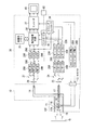
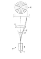
図1は、本実施形態である内視鏡装置のブロック図である。図2は、走査型光ファイバを模式的に示した図である。 FIG. 1 is a block diagram of an endoscope apparatus according to this embodiment. FIG. 2 is a diagram schematically showing a scanning optical fiber.
内視鏡装置は、スコープ10とプロセッサ30とを備え、スコープ10には、照明用の光ファイバ(以下、走査型光ファイバという)17と観察対象からの反射光を伝送する光ファイバ(以下、イメージファイバという)14が設けられている。イメージファイバ14の先端部は分岐しており、光学レンズ19の周囲に配置されている。スコープ10はプロセッサ30に着脱自在に接続され、また、プロセッサ30にはモニタ60が接続される。
The endoscope apparatus includes a
プロセッサ30には、R,G,Bの光をそれぞれ発光するレーザー光源20R、20G、20Bが設けられ、レーザードライバ22R、22G、22Bによって駆動される。R、G、Bの光を同時発光させることにより、白色光を観察対象に向けて照射する。
The
レーザー光源20R、20G、20Bによって放射された白色光は、ハーフミラー群24、集光レンズ25によって集光され、走査型光ファイバ17に入射する。入射した白色光は、走査型光ファイバ17を通ってスコープ先端部10Tへ送られる。
The white light emitted from the
図2に示すように、スコープ先端部10Tから射出する照明光を走査させるスキャナデバイス(以下、SFEスキャナという)16が、スコープ先端部10Tに設けられている。SFEスキャナ16はアクチュエータ18備え、スコープ10内に設けられたシングルモード型の走査型光ファイバ17は、円筒状アクチュエータ18の軸に挿通されて保持される。
As shown in FIG. 2, a scanner device (hereinafter referred to as an SFE scanner) 16 that scans illumination light emitted from the scope
スコープ先端部10Tに固定されたアクチュエータ18は、ピエゾ素子によるチューブ型アクチュエータであり、走査型光ファイバ17の先端部17Aを二次元的に共振させる。アクチュエータ18には、水平方向(X軸方向)、垂直方向(Y軸方向)にそれぞれ相対する2対の圧電素子(図示せず)が設けられ、水平方向の共振、垂直方向の共振をそれぞれ行う。
The
アクチュエータ18は、直交する2方向に沿って所定の共振モードでファイバ先端部17Aを共振させる。カンチレバー状に支持されるファイバ先端部17Aは、水平方向の共振、垂直方向の共振を受けることにより先端面17Sの向きを変え、軸中心から外側へ向けて螺旋状に動く。
The
その結果、先端面17Sから射出し、光学レンズ19を通って観察部位Sに到達する光の軌跡PTは、中心から外側へ向かう螺旋状の走査線になる。螺旋状走査線PTの径方向間隔をできる限り密にすることによって、観察対象Q全体が順に照射されていく。
As a result, the trajectory PT of the light emitted from the
観察対象Qで反射した光は、イメージファイバ14に入射し、プロセッサ30へ導かれる。イメージファイバ14からの反射光は、光学レンズ26、ハーフミラー群27によってR,G,Bの光に分離され、それぞれフォトセンサ28R、28G、28Bに入射する。フォトセンサ28R、28G、28Bは、それぞれR,G,Bの光をR,G,Bに応じた画素信号に変換する。
The light reflected by the observation object Q enters the
R,G,Bに応じた画素信号は、A/D変換器29R、29G、29Bにおいてデジタル画素信号に変換され、信号処理回路32へ送られる。信号処理回路32では、順次送られるR,G,Bのデジタル画素信号と照明光の走査位置とのマッピングにより、画素位置が特定され、1フレーム分のデジタル画素信号がラスタ配列される。1フレーム分のデジタル画素信号は、所定のフレームレートおよびサンプリングレートに従って検出され、一時的に画像用メモリ31に格納される。
Pixel signals corresponding to R, G, and B are converted into digital pixel signals by A /
信号処理回路32では、デジタル画素信号に対してホワイトバランス調整、色変換処理など様々な画像信号処理が施され、画像信号が生成される。1フレーム分の画像信号は、画像用メモリ31格納される。画像信号はエンコーダ37を介してモニタ60に送信され、フルカラーの観察画像がモニタ60に表示される。
The
CPU、ROM、RAMを含むコントローラ40は、プロセッサ30の動作を制御し、ROMには動作制御に関するプログラムが格納されている。コントローラ40は、信号処理回路32、タイミングコントローラ34、レーザードライバ22R、22G、22Bなどへ制御信号を出力する。
A
タイミングコントローラ34は、レーザードライバ22R、22G、22B、およびSFEスキャナ16に駆動信号を出力するファイバドライバ36A、36Bに対して同期信号を出力し、ファイバ先端部17Aの振動と発光タイミングを同期させる。また、タイミングコントローラ34は、画素信号を検出するためのクロックパルス信号(駆動信号)をフォトセンサ28R、28G、28Bへ出力する。
The
プロセッサ30のフロントパネルに設けられたモードスイッチ62は、高解像度モードを設定するためのスイッチであり、オペレータによって操作される。高解像度モードは、病変部の詳しい状況など診断に影響のある画像を高画質で観察するために設定される。高解像度モードが設定されると、後述するように、光ファイバ先端部17Aの駆動およびフレームレートを変更することにより、観察画像の解像度が変換される。
A
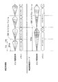
図3は、光ファイバ先端部駆動のタイミングチャートを示した図である。図4は、走査範囲を示した図である。図3、4を用いて、観察画像の解像度を変換する走査方法について説明する。 FIG. 3 is a timing chart for driving the optical fiber tip. FIG. 4 is a diagram showing the scanning range. A scanning method for converting the resolution of the observation image will be described with reference to FIGS.
円状に形成される1画面分の観察画像Mは、螺旋状走査によって形成される画像であり、径方向の走査ライン数は、スパイラル数に従う。ただし、走査位置が径方向に沿った同一直線を周回するのを1走査ラインとしてカウントする。 The observation image M for one screen formed in a circular shape is an image formed by spiral scanning, and the number of scanning lines in the radial direction follows the number of spirals. However, it is counted as one scanning line that the scanning position goes around the same straight line along the radial direction.
図4(a)に示すように、通常観察の場合、500×500ドット(ピクセル)の解像度で円状の観察画像Mが形成される。すなわち、走査開始位置に相当する画面中心Oから径方向に沿って250ピクセルの画素を形成する。そのため、スパイラル数は250となる。 As shown in FIG. 4A, in the case of normal observation, a circular observation image M is formed with a resolution of 500 × 500 dots (pixels). That is, a pixel of 250 pixels is formed along the radial direction from the screen center O corresponding to the scanning start position. Therefore, the number of spirals is 250.
通常観察では、1フレーム期間に250スパイラルの螺旋状走査をするように、光ファイバ先端部17Aが駆動される。図3には、光ファイバ先端部17Aの駆動波形が図示されており、走査開始から期間FAの間、スパイラル数250による螺旋状走査が行われる。期間FBの間に、光ファイバ先端部17Aが中心位置、すなわち走査開始位置へ戻る。
In normal observation, the
画素信号は所定のサンプリングレートに従って検出され、1周分(1スパイラル)の走査に対してサンプル、検出される画素データは、ここでは一定である(例えば、2000/スパイラル)。サンプリングレートに従った1画面分の画素信号は所定のフレームレートで周期的に読み出され、画像用メモリ31に格納される。フレームレートは、ここでは30fpsに定められている。
The pixel signal is detected according to a predetermined sampling rate, and the sampled and detected pixel data is constant here (for example, 2000 / spiral) for one round (one spiral) of scanning. Pixel signals for one screen according to the sampling rate are periodically read out at a predetermined frame rate and stored in the
一方、高解像度モードが設定されると、走査エリアを同じに保ったまま、スパイラル数を2倍(500スパイラル)に変更する。そして、走査速度(角速度)を変更しない代わりに、フレームレートを1/2倍(15fps)に変更する。光ファイバ先端部17Aの駆動波形の振幅増加率は、1/2倍に下げられる。
On the other hand, when the high resolution mode is set, the number of spirals is changed to double (500 spirals) while keeping the scanning area the same. Then, instead of changing the scanning speed (angular speed), the frame rate is changed to ½ times (15 fps). The amplitude increase rate of the drive waveform of the optical
その結果、形成される観察画像M1は、1000×1000ドットの解像度をもつ(図4(b)参照)。すなわち、中心Oから径方向外側に500ピクセルで観察画像M1が形成される。観察画像M1は、観察画像Mに比べて径方向に沿った画素密度が2倍となり、全体の画素数は4倍となる。 As a result, the formed observation image M1 has a resolution of 1000 × 1000 dots (see FIG. 4B). That is, the observation image M1 is formed with 500 pixels radially outward from the center O. Compared with the observation image M, the observation image M1 has twice the pixel density along the radial direction, and the total number of pixels is four times.
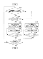
図5は、コントローラ40によって実行される走査制御処理を示したフローチャートである。
FIG. 5 is a flowchart showing a scanning control process executed by the
ステップS101では、高解像度モードが設定されているか否かが判断される。高解像度モードが設定されていない場合、ステップS106へ進み、通常観察に応じた走査が実行される。すなわち、250スパイラル数による螺旋状走査を実行するように、フレームレート(30fps)を設定し、ファイバドライバ36A、36Bを制御する。
In step S101, it is determined whether the high resolution mode is set. If the high resolution mode is not set, the process proceeds to step S106, and scanning according to normal observation is executed. That is, the frame rate (30 fps) is set so as to execute spiral scanning with 250 spirals, and the
そして、観察対象からの反射光に基づき、所定のサンプリングレートに従って時系列的に画素信号が検出される。250スパイラル数に対応する画素データが画像用メモリ31へ順次格納されるように、信号処理回路32が制御される(S107)。1フレーム分の画素データが検出されるまでステップS107が繰り返し実行される(S108)。
Based on the reflected light from the observation target, pixel signals are detected in time series according to a predetermined sampling rate. The
一方、ステップS101において、高解像度モードが設定されたと判断されると、ステップS102へ進む。ステップS102では、観察画像が静止状態であるか否かが判断される。具体的には、スコープ先端部10Tに設けられた加速度センサ15からの検出信号に基づき、スコープ先端部10Tに動きがあるか判断される。一方、信号処理回路32では、動きベクトル検出のため、前回のフレーム期間における1フレーム分の画像データとの差分データが生成される。
On the other hand, if it is determined in step S101 that the high resolution mode is set, the process proceeds to step S102. In step S102, it is determined whether or not the observation image is stationary. Specifically, based on a detection signal from the
オペレータがスコープ先端部10Tを器官内部へ挿入させる間、画面に表示される観察画像は動きの激しい映像となり、高解像度の観察画像を得る必要がない。逆に、現在のスコープ先端部10Tの位置を移動させながら診断するため、フレームレートの高い画像が必要となる。
While the operator inserts the
したがって、スコープ先端部10Tが動いている場合、撮影状態が動作状態にあると判断する。一方、差分データによって動きベクトルが検出されても、スコープ先端部10Tによる画像の動きであるのか、脈動などの器官自身の動きであるのか判断できない。そのため、スコープ先端部10Tの動き、および動きベクトルの両方が検出される場合、撮影状態が動作状態にあると判断する。
Therefore, when the scope
撮影状態が動作状態にある場合、ステップS106へ進み、通常観察と同様の螺旋状走査が行われる。一方、撮影状態が静止状態にある、すなわちスコープ先端部10Tの動きが無く、観察対象を十分観察するため高解像度の画像を必要としている状態と判断し、ステップS103へ進む。
When the photographing state is the operating state, the process proceeds to step S106, and the same spiral scanning as in normal observation is performed. On the other hand, it is determined that the photographing state is stationary, that is, the
ステップS103では、同じ走査エリア(走査対象)に対し、スパイラル数500による走査が実行されるように、ファイバドライバ36A、36Bが制御される。それとともに、フレームレートが1/2倍のレート(15fps)に設定される。そして、500スパイラルに応じた画像データが画像用メモリ31へ順次格納される(S104)。1フレーム分の画素データが格納されるまでステップS104が繰り返し実行される(S105)。
In step S103, the
1フレーム分の画素データが格納されると、ステップS101へ戻り、ステップS101〜S108が繰り返される。すなわち、フレーム期間ごとに、高解像度モードの設定状態、撮影状態に応じた走査が実行される。走査終了の操作がなされると、走査制御処理は終了する。 When pixel data for one frame is stored, the process returns to step S101, and steps S101 to S108 are repeated. That is, scanning corresponding to the setting state of the high resolution mode and the shooting state is executed for each frame period. When the scanning end operation is performed, the scanning control process ends.
このように本実施形態によれば、スコープ先端部を共振させて螺旋状に光を走査させる内視鏡装置において、高解像度モードの場合、走査スパイラル数を2倍にし、フレームレートを1/2に下げる(S103)。これにより、解像度の向上した観察画像M1が得られる。撮影状態がスコープ先端部を動かすような動作状態の場合、通常観察におけるスパイラル数、フレームレートで螺旋状走査を行う。 As described above, according to the present embodiment, in the endoscope apparatus that scans light spirally by resonating the scope tip, in the high resolution mode, the number of scanning spirals is doubled and the frame rate is halved. (S103). Thereby, an observation image M1 with improved resolution is obtained. When the imaging state is an operation state in which the scope tip is moved, spiral scanning is performed with the number of spirals and the frame rate in normal observation.
従来型の内視鏡装置のように、CCDなどの2次元イメージセンサを使用した場合、解像度はイメージセンサの画素間隔に依存し、イメージセンサの画素数を限度にして解像度が定まる。したがって、解像度変換を行う場合、間引き処理などによって解像度を下げるしかない。 When a two-dimensional image sensor such as a CCD is used as in a conventional endoscope apparatus, the resolution depends on the pixel interval of the image sensor, and the resolution is determined by limiting the number of pixels of the image sensor. Therefore, when resolution conversion is performed, there is no choice but to reduce the resolution by thinning processing or the like.
一方、本実施形態では、走査型光ファイバを制御することによってサンプル画素の密度を径方向に変化させ、フレーム期間ごとに解像度を高解像度、通常解像度の間で切り替えることが可能となる。したがって、高解像度の要求される場面で解像度の高い観察画像を表示することができる。またフレームレートを落として走査速度を変えないため、無理に光ファイバ先端部を高速で駆動することなく、高解像度の観察画像を得ることができる。 On the other hand, in this embodiment, the density of the sample pixels is changed in the radial direction by controlling the scanning optical fiber, and the resolution can be switched between the high resolution and the normal resolution for each frame period. Therefore, an observation image with high resolution can be displayed in a scene where high resolution is required. In addition, since the scanning rate is not changed by reducing the frame rate, a high-resolution observation image can be obtained without forcibly driving the optical fiber tip at high speed.
一方、高解像度モードにおいても、撮影状態が動作状態になると、通常観察と同じ走査が行われる。そのため、高画質の画像が必要なく、スコープ先端部10Tの位置、および観察対象となっている器官部分を確認するのに十分な観察画像を表示することが可能である。
On the other hand, even in the high resolution mode, when the photographing state becomes the operating state, the same scanning as in normal observation is performed. Therefore, a high-quality image is not necessary, and it is possible to display an observation image sufficient to confirm the position of the scope
さらに、撮影状態が静止状態であるか否かを2つの動き、すなわちスコープ先端部10Tの動きと、観察画像の動きから判断している。そのため、器官自身が動くような観察対象でも、誤って動作状態と判断されることなく、高解像度の観察画像が表示される。
Further, whether or not the photographing state is a stationary state is determined from two movements, that is, the movement of the scope
なお、オペレータの操作によらず、自動的に高解像度モードに切り替える構成にすることも可能である。さらに、観察画像の動きベクトルだけ、あるいはスコープ先端部の動きだけで高解像度モードにおける通常スパイラル数への変更を行うことも出来る。 It is also possible to adopt a configuration in which the mode is automatically switched to the high resolution mode regardless of the operator's operation. Furthermore, the number of spirals in the high resolution mode can be changed only by the motion vector of the observation image or the motion of the scope tip.
サンプリングレート数、スパイラル数は任意に設定可能であり、上記以外の解像度に変更するように構成してもよい。また、フレームレートをそのまま一次、ファイバ先端部を2倍の高速に動かすことも可能である。さらには、光ファイバ先端部のスパイラル走査を変更する代わりに、1スパイラル当たりのサンプリング数(画素サンプリング)を変更するように構成することも可能である。 The number of sampling rates and the number of spirals can be arbitrarily set, and the resolution may be changed to a resolution other than the above. It is also possible to move the fiber rate at the primary speed and the fiber tip as fast as twice. Furthermore, it is also possible to change the sampling number (pixel sampling) per spiral instead of changing the spiral scanning of the optical fiber tip.
なお、螺旋状走査はファイバ先端部を共振させる以外の構成にすることも可能である。 It should be noted that the helical scanning can be configured other than resonating the fiber tip.
10 ビデオスコープ
16 SFEスキャナ
17 走査型光ファイバ
20R、20G、20B レーザー光源
30 プロセッサ
40 コントローラ
10
Claims (9)
光ファイバ先端部を駆動することによって、観察対象に対し照明光を螺旋状に走査させる走査手段と、
観察対象からの反射光に基づいて画素信号を検出し、観察画像を生成する画像形成手段と、
前記光ファイバ先端部の駆動もしくは画素サンプリングを制御することにより、撮影状況に応じて観察画像の解像度を変換可能な解像度調整手段と
を備えたことを特徴とする内視鏡装置。 An optical fiber that transmits illumination light from the light source to the scope tip,
Scanning means for spirally scanning the illumination light with respect to the observation target by driving the tip of the optical fiber;
An image forming means for detecting a pixel signal based on reflected light from an observation object and generating an observation image;
An endoscope apparatus comprising: a resolution adjusting unit capable of converting a resolution of an observation image according to a photographing situation by controlling driving of the optical fiber tip or pixel sampling.
前記スコープ先端部の動きを検出する動き検出センサとをさらに有し、
前記解像度調整手段が、前記スコープ先端部の動きおよび観察画像の動き両方に基づいて、静止状態であるか否かを判断することを特徴とする請求項2に記載の内視鏡装置。 Image motion detection means for detecting the motion of the observation image;
A motion detection sensor for detecting the movement of the scope tip,
The endoscope apparatus according to claim 2, wherein the resolution adjustment unit determines whether or not a stationary state is based on both the movement of the distal end portion of the scope and the movement of the observation image.
前記解像度調整手段が、高解像度モードの場合、観察画像の解像度を上げるとともに、高解像度モードにおいて動作状態が検出されると、解像度を下げることを特徴とする請求項1に記載の内視鏡装置。 A mode setting means for setting a high resolution mode for increasing the resolution of the observation image;
The endoscope apparatus according to claim 1, wherein when the resolution adjusting unit is in a high resolution mode, the resolution of the observation image is increased and, when an operation state is detected in the high resolution mode, the resolution is decreased. .
静止状態の場合、走査エリアに対する走査スパイラル数を増加させることによって、観察画像の解像度を上げる解像度調整手段と
を備えたことを特徴とする内視鏡解像度調整装置。 An imaging state determination unit that determines whether or not the observation target is in a stationary state while scanning the illumination light in a spiral shape;
An endoscope resolution adjustment device comprising: a resolution adjustment unit that increases the resolution of an observation image by increasing the number of scanning spirals for a scanning area in a stationary state.
静止状態の場合、走査エリアに対する走査スパイラル数を増加させることによって、観察画像の解像度を上げる解像度調整手段と
を機能させることを特徴とするプログラム。 An imaging state determination unit that determines whether or not the observation target is in a stationary state while scanning the illumination light in a spiral shape;
A program characterized by causing a resolution adjustment means for increasing the resolution of an observation image to function by increasing the number of scanning spirals for a scanning area in a stationary state.
静止状態の場合、走査エリアに対する走査スパイラル数を増加させることによって、観察画像の解像度を上げることを特徴とする内視鏡解像度調整方法。
While illuminating light is scanned with respect to the observation target, it is determined whether or not it is stationary,
An endoscope resolution adjustment method characterized by increasing the resolution of an observed image by increasing the number of scanning spirals for a scanning area in a stationary state.
Priority Applications (3)
| Application Number | Priority Date | Filing Date | Title |
|---|---|---|---|
| JP2008326277A JP2010142597A (en) | 2008-12-22 | 2008-12-22 | Endoscope system |
| US12/644,191 US20100157037A1 (en) | 2008-12-22 | 2009-12-22 | Endoscope system with scanning function |
| DE102009059978A DE102009059978A1 (en) | 2008-12-22 | 2009-12-22 | Endoscope system with scanning function |
Applications Claiming Priority (1)
| Application Number | Priority Date | Filing Date | Title |
|---|---|---|---|
| JP2008326277A JP2010142597A (en) | 2008-12-22 | 2008-12-22 | Endoscope system |
Publications (1)
| Publication Number | Publication Date |
|---|---|
| JP2010142597A true JP2010142597A (en) | 2010-07-01 |
Family
ID=42265441
Family Applications (1)
| Application Number | Title | Priority Date | Filing Date |
|---|---|---|---|
| JP2008326277A Withdrawn JP2010142597A (en) | 2008-12-22 | 2008-12-22 | Endoscope system |
Country Status (3)
| Country | Link |
|---|---|
| US (1) | US20100157037A1 (en) |
| JP (1) | JP2010142597A (en) |
| DE (1) | DE102009059978A1 (en) |
Cited By (11)
| Publication number | Priority date | Publication date | Assignee | Title |
|---|---|---|---|---|
| JP2012165804A (en) * | 2011-02-10 | 2012-09-06 | Hoya Corp | Processor for electronic endoscope, and electronic endoscope apparatus |
| WO2013111604A1 (en) * | 2012-01-26 | 2013-08-01 | オリンパス株式会社 | Light scanning observation device |
| JP2015139564A (en) * | 2014-01-29 | 2015-08-03 | オリンパス株式会社 | Scanning type endoscope apparatus and control method thereof |
| JP2015532040A (en) * | 2012-08-15 | 2015-11-05 | インテュイティブ サージカル オペレーションズ, インコーポレイテッド | Method and system for video streaming |
| WO2016116968A1 (en) * | 2015-01-23 | 2016-07-28 | オリンパス株式会社 | Optical scanning device |
| WO2016185595A1 (en) * | 2015-05-21 | 2016-11-24 | オリンパス株式会社 | Scanning-type observation device |
| WO2017068722A1 (en) * | 2015-10-23 | 2017-04-27 | オリンパス株式会社 | Optical scanning device and method for controlling optical scanning device |
| JP2017176773A (en) * | 2016-03-31 | 2017-10-05 | 国立大学法人浜松医科大学 | Surgery support system, surgery support method, and surgery support program |
| US10534168B2 (en) | 2015-10-22 | 2020-01-14 | Olympus Corporation | Light-scanning apparatus and light-scanning-apparatus control method |
| WO2020084752A1 (en) * | 2018-10-26 | 2020-04-30 | オリンパス株式会社 | Endoscopic image processing device, endoscopic image processing method, and endoscopic image processing program |
| JP2020525055A (en) * | 2017-06-29 | 2020-08-27 | ソニー株式会社 | Medical imaging system, method and computer program |
Families Citing this family (19)
| Publication number | Priority date | Publication date | Assignee | Title |
|---|---|---|---|---|
| US8212884B2 (en) * | 2007-05-22 | 2012-07-03 | University Of Washington | Scanning beam device having different image acquisition modes |
| JP5715372B2 (en) * | 2010-10-15 | 2015-05-07 | オリンパス株式会社 | Image processing apparatus, method of operating image processing apparatus, and endoscope apparatus |
| JP5745922B2 (en) * | 2011-04-28 | 2015-07-08 | オリンパス株式会社 | Optical scanning observation device |
| CA2835870A1 (en) | 2011-05-12 | 2012-11-15 | Olive Medical Corporation | Pixel array area optimization using stacking scheme for hybrid image sensor with minimal vertical interconnects |
| MX344146B (en) | 2012-07-26 | 2016-12-07 | Depuy Synthes Products Inc | Camera system with minimal area monolithic cmos image sensor. |
| US9516239B2 (en) | 2012-07-26 | 2016-12-06 | DePuy Synthes Products, Inc. | YCBCR pulsed illumination scheme in a light deficient environment |
| AU2013295553B2 (en) | 2012-07-26 | 2017-10-19 | DePuy Synthes Products, Inc. | Continuous video in a light deficient environment |
| JP6404318B2 (en) | 2013-03-15 | 2018-10-10 | デピュイ・シンセス・プロダクツ・インコーポレイテッド | Integrated optical energy control of laser pulses |
| AU2014233464B2 (en) | 2013-03-15 | 2018-11-01 | DePuy Synthes Products, Inc. | Scope sensing in a light controlled environment |
| EP2967294B1 (en) | 2013-03-15 | 2020-07-29 | DePuy Synthes Products, Inc. | Super resolution and color motion artifact correction in a pulsed color imaging system |
| CN105246394B (en) | 2013-03-15 | 2018-01-12 | 德普伊新特斯产品公司 | It is synchronous without the imaging sensor of input clock and data transfer clock |
| US10750933B2 (en) | 2013-03-15 | 2020-08-25 | DePuy Synthes Products, Inc. | Minimize image sensor I/O and conductor counts in endoscope applications |
| US10084944B2 (en) | 2014-03-21 | 2018-09-25 | DePuy Synthes Products, Inc. | Card edge connector for an imaging sensor |
| WO2015182198A1 (en) * | 2014-05-28 | 2015-12-03 | オリンパス株式会社 | Optical scan observation device and optical scan observation device operation method |
| WO2016111178A1 (en) * | 2015-01-05 | 2016-07-14 | オリンパス株式会社 | Endoscope system |
| DE102019132384A1 (en) | 2019-11-28 | 2021-06-02 | Carl Zeiss Meditec Ag | Method for creating a high-resolution image, data processing system and optical observation device |
| DE102019132514B3 (en) * | 2019-11-29 | 2021-02-04 | Carl Zeiss Meditec Ag | Optical observation device and method and data processing system for determining information for distinguishing between tissue fluid cells and tissue cells |
| DE102020107519A1 (en) | 2020-03-18 | 2021-09-23 | Carl Zeiss Meditec Ag | Device and method for classifying a brain tissue area, computer program, non-transitory computer-readable storage medium and data processing device |
| CN115251808B (en) * | 2022-09-22 | 2022-12-16 | 深圳市资福医疗技术有限公司 | Capsule endoscope control method and device based on scene guidance and storage medium |
Family Cites Families (5)
| Publication number | Priority date | Publication date | Assignee | Title |
|---|---|---|---|---|
| US6294775B1 (en) * | 1999-06-08 | 2001-09-25 | University Of Washington | Miniature image acquistion system using a scanning resonant waveguide |
| US7159782B2 (en) | 2004-12-23 | 2007-01-09 | University Of Washington | Methods of driving a scanning beam device to achieve high frame rates |
| US7333700B2 (en) * | 2006-06-01 | 2008-02-19 | University Of Washington | Scanning apparatus and endoscope |
| US20080039693A1 (en) * | 2006-08-14 | 2008-02-14 | University Of Washington | Endoscope tip unit and endoscope with scanning optical fiber |
| US8212884B2 (en) * | 2007-05-22 | 2012-07-03 | University Of Washington | Scanning beam device having different image acquisition modes |
-
2008
- 2008-12-22 JP JP2008326277A patent/JP2010142597A/en not_active Withdrawn
-
2009
- 2009-12-22 DE DE102009059978A patent/DE102009059978A1/en not_active Withdrawn
- 2009-12-22 US US12/644,191 patent/US20100157037A1/en not_active Abandoned
Cited By (27)
| Publication number | Priority date | Publication date | Assignee | Title |
|---|---|---|---|---|
| JP2012165804A (en) * | 2011-02-10 | 2012-09-06 | Hoya Corp | Processor for electronic endoscope, and electronic endoscope apparatus |
| US9651774B2 (en) | 2012-01-26 | 2017-05-16 | Olympus Corporation | Optical scanning observation apparatus having variable sampling time, and method and computer readable storage device |
| WO2013111604A1 (en) * | 2012-01-26 | 2013-08-01 | オリンパス株式会社 | Light scanning observation device |
| JP7114760B2 (en) | 2012-08-15 | 2022-08-08 | インテュイティブ サージカル オペレーションズ, インコーポレイテッド | Method and system for video streaming |
| JP2015532040A (en) * | 2012-08-15 | 2015-11-05 | インテュイティブ サージカル オペレーションズ, インコーポレイテッド | Method and system for video streaming |
| JP7379609B2 (en) | 2012-08-15 | 2023-11-14 | インテュイティブ サージカル オペレーションズ, インコーポレイテッド | Method and system for video streaming |
| US11889975B2 (en) | 2012-08-15 | 2024-02-06 | Intuitive Surgical Operations, Inc. | Methods and systems for optimizing video streaming |
| JP2022136244A (en) * | 2012-08-15 | 2022-09-15 | インテュイティブ サージカル オペレーションズ, インコーポレイテッド | Method and system for video streaming |
| JP2019208262A (en) * | 2012-08-15 | 2019-12-05 | インテュイティブ サージカル オペレーションズ, インコーポレイテッド | Methods and systems for video streaming |
| US10806325B2 (en) | 2012-08-15 | 2020-10-20 | Intuitive Surgical Operations, Inc. | Methods and systems for optimizing video streaming |
| JP2021072644A (en) * | 2012-08-15 | 2021-05-06 | インテュイティブ サージカル オペレーションズ, インコーポレイテッド | Methods and systems for video streaming |
| JP2018042293A (en) * | 2012-08-15 | 2018-03-15 | インテュイティブ サージカル オペレーションズ, インコーポレイテッド | Method and system for video streaming |
| WO2015115277A1 (en) * | 2014-01-29 | 2015-08-06 | オリンパス株式会社 | Scanning endoscopic device and control method therefor |
| JP2015139564A (en) * | 2014-01-29 | 2015-08-03 | オリンパス株式会社 | Scanning type endoscope apparatus and control method thereof |
| WO2016116968A1 (en) * | 2015-01-23 | 2016-07-28 | オリンパス株式会社 | Optical scanning device |
| JPWO2016116968A1 (en) * | 2015-01-23 | 2017-12-07 | オリンパス株式会社 | Optical scanning device |
| CN107209364A (en) * | 2015-01-23 | 2017-09-26 | 奥林巴斯株式会社 | Light scanning apparatus |
| JPWO2016185595A1 (en) * | 2015-05-21 | 2018-03-15 | オリンパス株式会社 | Scanning observation device |
| WO2016185595A1 (en) * | 2015-05-21 | 2016-11-24 | オリンパス株式会社 | Scanning-type observation device |
| US10534168B2 (en) | 2015-10-22 | 2020-01-14 | Olympus Corporation | Light-scanning apparatus and light-scanning-apparatus control method |
| US10356287B2 (en) | 2015-10-23 | 2019-07-16 | Olympus Corporation | Optical scanning apparatus and method of controlling optical scanning apparatus |
| JPWO2017068722A1 (en) * | 2015-10-23 | 2018-08-09 | オリンパス株式会社 | Optical scanning device and optical scanning device control method |
| WO2017068722A1 (en) * | 2015-10-23 | 2017-04-27 | オリンパス株式会社 | Optical scanning device and method for controlling optical scanning device |
| JP2017176773A (en) * | 2016-03-31 | 2017-10-05 | 国立大学法人浜松医科大学 | Surgery support system, surgery support method, and surgery support program |
| JP2020525055A (en) * | 2017-06-29 | 2020-08-27 | ソニー株式会社 | Medical imaging system, method and computer program |
| WO2020084752A1 (en) * | 2018-10-26 | 2020-04-30 | オリンパス株式会社 | Endoscopic image processing device, endoscopic image processing method, and endoscopic image processing program |
| US11992177B2 (en) | 2018-10-26 | 2024-05-28 | Olympus Corporation | Image processing device for endoscope, image processing method for endoscope, and recording medium |
Also Published As
| Publication number | Publication date |
|---|---|
| US20100157037A1 (en) | 2010-06-24 |
| DE102009059978A1 (en) | 2010-07-29 |
Similar Documents
| Publication | Publication Date | Title |
|---|---|---|
| JP2010142597A (en) | Endoscope system | |
| JP5342869B2 (en) | Endoscope apparatus, endoscope illumination apparatus, image forming apparatus, operation method of endoscope illumination apparatus, and operation method of image formation apparatus | |
| JP5467756B2 (en) | Endoscope device | |
| US11666209B2 (en) | Video endoscopy | |
| JP2010125270A (en) | Endoscope apparatus | |
| US20100137684A1 (en) | Endoscope system with scanning function | |
| US11457801B2 (en) | Image processing device, image processing method, and endoscope system | |
| JP5753409B2 (en) | Panorama image creation method and three-dimensional laser scanner | |
| JP5543254B2 (en) | Laser scanning imaging device | |
| JP2010131161A (en) | Optical scanning endoscope processor, image processing apparatus, and optical scanning endoscope system | |
| US10499803B2 (en) | Vocal cord stroboscopy | |
| JPWO2012033200A1 (en) | Imaging device | |
| JP7230174B2 (en) | Endoscope system, image processing device, and control method for image processing device | |
| JP2010142605A (en) | Endoscope system | |
| JP2008068021A (en) | Electronic endoscope apparatus | |
| JP2011125617A (en) | Endoscope apparatus | |
| JP2022136184A (en) | Control device, endoscope system and method of operating the control device | |
| JP2011055939A (en) | Endoscope apparatus | |
| US20190167071A1 (en) | Medical imaging device | |
| JP2011004920A (en) | Endoscope apparatus | |
| JP2010131112A (en) | Endoscope system | |
| JP6179942B2 (en) | Scanning confocal endoscope system | |
| JP2011004929A (en) | Endoscope apparatus | |
| JP2010226372A (en) | Digital camera | |
| JP2010131110A (en) | Endoscope system |
Legal Events
| Date | Code | Title | Description |
|---|---|---|---|
| A621 | Written request for application examination |
Free format text: JAPANESE INTERMEDIATE CODE: A621 Effective date: 20110808 |
|
| A761 | Written withdrawal of application |
Free format text: JAPANESE INTERMEDIATE CODE: A761 Effective date: 20121126 |