US10312862B2 - Up-down converter - Google Patents
Up-down converter Download PDFInfo
- Publication number
- US10312862B2 US10312862B2 US15/540,682 US201515540682A US10312862B2 US 10312862 B2 US10312862 B2 US 10312862B2 US 201515540682 A US201515540682 A US 201515540682A US 10312862 B2 US10312862 B2 US 10312862B2
- Authority
- US
- United States
- Prior art keywords
- signal
- frequency
- filter
- local
- down converter
- Prior art date
- Legal status (The legal status is an assumption and is not a legal conclusion. Google has not performed a legal analysis and makes no representation as to the accuracy of the status listed.)
- Active, expires
Links
- 238000001914 filtration Methods 0.000 claims description 8
- 238000004891 communication Methods 0.000 description 16
- 238000010586 diagram Methods 0.000 description 8
- 238000006243 chemical reaction Methods 0.000 description 4
- 238000000034 method Methods 0.000 description 3
- 230000005540 biological transmission Effects 0.000 description 2
- 238000012986 modification Methods 0.000 description 2
- 230000004048 modification Effects 0.000 description 2
- 101500023488 Lithobates catesbeianus GnRH-associated peptide 1 Proteins 0.000 description 1
- 101500022510 Lithobates catesbeianus GnRH-associated peptide 2 Proteins 0.000 description 1
- 238000013461 design Methods 0.000 description 1
- 238000005516 engineering process Methods 0.000 description 1
- 238000004519 manufacturing process Methods 0.000 description 1
- 238000012545 processing Methods 0.000 description 1
- 239000002699 waste material Substances 0.000 description 1
Images



Classifications
-
- H—ELECTRICITY
- H03—ELECTRONIC CIRCUITRY
- H03D—DEMODULATION OR TRANSFERENCE OF MODULATION FROM ONE CARRIER TO ANOTHER
- H03D7/00—Transference of modulation from one carrier to another, e.g. frequency-changing
- H03D7/16—Multiple-frequency-changing
-
- H—ELECTRICITY
- H03—ELECTRONIC CIRCUITRY
- H03D—DEMODULATION OR TRANSFERENCE OF MODULATION FROM ONE CARRIER TO ANOTHER
- H03D7/00—Transference of modulation from one carrier to another, e.g. frequency-changing
- H03D7/16—Multiple-frequency-changing
- H03D7/161—Multiple-frequency-changing all the frequency changers being connected in cascade
-
- H—ELECTRICITY
- H03—ELECTRONIC CIRCUITRY
- H03D—DEMODULATION OR TRANSFERENCE OF MODULATION FROM ONE CARRIER TO ANOTHER
- H03D7/00—Transference of modulation from one carrier to another, e.g. frequency-changing
- H03D7/18—Modifications of frequency-changers for eliminating image frequencies
-
- H—ELECTRICITY
- H04—ELECTRIC COMMUNICATION TECHNIQUE
- H04B—TRANSMISSION
- H04B1/00—Details of transmission systems, not covered by a single one of groups H04B3/00 - H04B13/00; Details of transmission systems not characterised by the medium used for transmission
- H04B1/06—Receivers
- H04B1/16—Circuits
- H04B1/30—Circuits for homodyne or synchrodyne receivers
Definitions
- the inventive concept relates to an up-down converter, and more particularly, to up-down converter for controlling the frequency of a first local signal and a second local signal based on a frequency of an input radio frequency (RF) signal.
- RF radio frequency
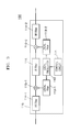
- FIG. 1 is a schematic block diagram of part of a communication device including a conventional up-down converter.
- FIG. 2 is a diagram of frequency bands processed by the up-down converter shown in FIG. 1 .
- the communication device is a repeater capable of radio transmission, such as a node unit of a distributed antenna system, a radio frequency (RF) repeater, or an interference cancellation system (ICS) repeater.
- RF radio frequency
- ICS interference cancellation system
- a conventional communication device 10 to perform signal processing, such as intermediate frequency (IF) conversion, on a plurality of frequency bands (e.g., RB 1 , RB 2 , and RB 3 ), a conventional communication device 10 requires up-down converters (e.g., 11 , 12 , and 13 ) for the respective frequency bands RB 1 , RB 2 , and RB 3 .
- up-down converters e.g., 11 , 12 , and 13
- the up-down converters 11 , 12 , and 13 have substantially the same structures which include a control circuit, a local oscillator, a first local filter, a second local filter, a first RF filter, a second RF filter, a first mixer, a second mixer, and a first IF filter, parameters (e.g., a central frequency and a bandwidth) need to be designed different among the structures so that different frequency bands can be processed. This results in an unnecessary waste of expense and time during design and manufacturing. In addition, it is inconvenient to separately manage the up-down converters 11 , 12 , and 13 during the operation of the communication device 10 .
- the present invention provides an up-down converter for controlling the frequency of a first local signal and a second local signal based on a frequency of an input radio frequency (RF) signal, thereby operating in a plurality of frequency bands in a communication device.
- RF radio frequency
- an up-down converter includes a first mixer configured to convert an input radio frequency (RF) signal into an intermediate frequency (IF) signal using a first local signal; an IF filter configured to filter the IF signal converted by the first mixer; a second mixer configured to convert the IF signal, which has been filtered by the IF filter, into an output RF signal using a second local signal; and a local oscillator configured to control a frequency of the first local signal and the second local signal based on a frequency of the input RF signal.
- RF radio frequency
- IF filter intermediate frequency
- IF filter configured to filter the IF signal converted by the first mixer
- a second mixer configured to convert the IF signal, which has been filtered by the IF filter, into an output RF signal using a second local signal
- a local oscillator configured to control a frequency of the first local signal and the second local signal based on a frequency of the input RF signal.
- the up-down converter may perform an operation on the input RF signal comprising a plurality of frequency bands.
- the up-down converter may further include a first local filter configured to filter the first local signal and to provide a filtered first local signal to the first mixer; and a second local filter configured to filter the second local signal and to provide a filtered second local signal to the second mixer.
- the local oscillator may control the frequency of the first local signal and the second local signal based on the input RF signal according to a control signal output from a control circuit.
- the up-down converter may further include a first RF filter configured to filter the input RF signal and to transmit a filtered input RF signal to the first mixer; and a second RF filter configured to filter out an image frequency from the output RF signal.
- each of the first and second RF filters may pass all of the plurality of frequency bands.
- a bandwidth of the IF filter may be the same as or greater than a bandwidth of a frequency band having the greatest bandwidth among the plurality of frequency bands.
- the local oscillator may control the frequency of the first local signal and the second local signal so that a partial frequency section of a filtering band to which the input RF signal belongs is passed, where the partial frequency section may be at a side of a frequency band nearest to a frequency band of the input RF signal.
- a width of the partial frequency section may be the same as a bandwidth of the frequency band of the input RF signal.
- an up-down converter controls the frequency of a first local signal and a second local signal based on a frequency of an input radio frequency (RF) signal, thereby operating in a plurality of frequency bands. Accordingly, various types of communication devices in which the up-down converter is mounted can be easily designed and manufactured to provide multiband support; the convenience of management is increased.
- RF radio frequency
- FIG. 1 is a schematic block diagram of part of a communication device including a conventional up-down converter.
- FIG. 2 is a diagram of frequency bands processed by the up-down converter shown in FIG. 1 .
- FIG. 3 is a schematic block diagram of a communication device including an up-down converter according to an embodiment of the inventive concept.
- FIG. 4 is a diagram of frequency bands processed by the up-down converter shown in FIG. 3 .
- terminology such as “part (or unit)”, “ ⁇ or”, “ ⁇ er”, and “module” may indicate a unit which processes at least one function or operation and may be implemented by hardware, software, or a combination thereof.
- elements are just defined by their main functions. In detail, two or more elements may be integrated into one element or one element may be divided into two or more elements by their subdivided functions. Each of the elements which will be described below may partially or fully perform the function of another element in addition to its own main function and part of the main function of each element may be exclusively performed by another element.
- FIG. 3 is a schematic block diagram of a communication device including an up-down converter according to an embodiment of the inventive concept.
- FIG. 4 is a diagram of frequency bands processed by the up-down converter shown in FIG. 3 .
- a communication device 100 may include an up-down converter 110 .
- the communication device 100 may be a node unit, e.g., a headend unit linked to a base station or a remote unit linked to a user terminal, included in a distributed antenna system.
- the communication device 100 may be a repeater capable of wireless transmission, such as a radio frequency (RF) repeater or an interference cancellation system (ICS) repeater.
- RF radio frequency
- ICS interference cancellation system
- the up-down converter 110 may include a control circuit 111 , a local oscillator 112 , a first local filter 113 - 1 , a second local filter 113 - 2 , a first RF filter 114 - 1 , a second RF filter 114 - 2 , a first mixer 115 - 1 , a second mixer 115 - 2 , and an intermediate frequency (IF) filter 116 .
- IF intermediate frequency
- an input RF signal including a plurality of frequency bands may be input to the up-down converter 110 without being separated.
- the control circuit 111 may control the local oscillator 112 based on a frequency of the input RF signal to control the frequency of a first local signal used for down-conversion and of a second local signal used for up-conversion.
- the local oscillator 112 may generate the first local signal and transmit the first local signal to the first local filter 113 - 1 under the control of the control circuit 111 .
- the local oscillator 112 may generate the second local signal and transmit the second local signal to the second local filter 113 - 2 under the control of the control circuit 111 .
- the first local filter 113 - 1 may filter the first local signal and transmit a filtered first local signal to the first mixer 115 - 1 .
- the first local filter 113 - 1 may be implemented as a band pass filter (BPF).
- the second local filter 113 - 2 may filter the second local signal and transmit a filtered second local signal to the second mixer 115 - 2 .
- the second local filter 113 - 2 may be implemented as a BPF.
- the first RF filter 114 - 1 may receive and filter the input RF signal and transmit a filtered input RF signal to the first mixer 115 - 1 .
- the first RF filter 114 - 1 may be implemented as a BPF.
- the first RF filter 114 - 1 may pass all of a plurality of frequency bands RB 1 , RB 2 , and RB 3 .
- the first mixer 115 - 1 may convert the filtered input RF signal received from the first RF filter 114 - 1 into an IF signal using the filtered first local signal received from the first local filter 113 - 1 . In other words, the first mixer 115 - 1 may down-convert the input RF signal using the first local signal.
- the IF filter 116 may filter the IF signal received from the first mixer 115 - 1 to pass a signal in a specific frequency band.
- the IF filter 116 may be implemented as a BPF.
- the IF filter 116 may transmit a filtered IF signal to the second mixer 115 - 2 .
- the bandwidth of the IF filter 116 may be designed to be the same as or greater than the bandwidth of a frequency band having the greatest bandwidth among the plurality of frequency bands RB 1 , RB 2 , and RB 3 .
- the second mixer 115 - 2 may convert the filtered IF signal received from the IF filter 116 into an output RF signal using the filtered second local signal received from the second local filter 113 - 2 .
- the second mixer 115 - 2 may up-convert the filtered IF signal using the second local signal.
- the second RF filter 114 - 2 may receive the output RF signal from the second mixer 115 - 2 and filter the output RF signal.
- the second RF filter 114 - 2 may filter out an image frequency which has occurred during the conversion of the second mixer 115 - 2 .
- the second RF filter 114 - 2 may be implemented as a BPF.
- the second RF filter 114 - 2 may pass all of the plurality of frequency bands RB 1 , RB 2 , and RB 3 .
- the first frequency band RB 1 has a central frequency of 800 MHz and a bandwidth of 20 MHz
- the second frequency band RB 2 has a central frequency of 850 MHz and a bandwidth of 30 MHz
- the third frequency band RB 3 has a central frequency of 890 MHz and a bandwidth of 40 MHz.
- a gap GAP 1 between the first frequency band RB 1 and the second frequency band RB 2 is narrower than a gap GAP 2 between the second frequency band RB 2 and the third frequency band RB 3 .
- all elements of the up-down converter 110 are designed to be suitable to operations in each of the frequency bands RB 1 , RB 2 , and RB 3 .
- the central frequency of local signals output from the local oscillator 112 may be controlled in a range of 700 to 790 MHz according to the frequency of an input RF signal.
- the local oscillator 112 may control the frequency of a first local signal and a second local signal so that the IF filter 116 passes a partial frequency section PF 1 of a filtering band, e.g., FB 1 , to which an input RF signal belongs.
- the partial frequency section PF 1 is at the side of the frequency band RB 2 nearest to the frequency band RB 1 of the input RF signal.
- the local oscillator 112 may control the frequency of a first local signal and a second local signal so that the IF filter 116 passes a partial frequency section PF 2 of a filtering band, e.g., FB 2 , to which an input RF signal belongs.
- the partial frequency section PF 2 is at the side of the frequency band RB 1 nearest to the frequency band RB 2 of the input RF signal.
- a bandwidth, i.e., a filtering band FB 1 , FB 2 , or FB 3 of the IF filter 116 is designed to be the same as or greater than a bandwidth (e.g., 40 MHz) of the frequency band, e.g., RB 3 , having the greatest bandwidth among the plurality of frequency bands RB 1 , RB 2 , and RB 3
- the IF filter 116 may perform filtering corresponding to a real band of each frequency band RB 1 , RB 2 , or RB 3 .
- the first local filter 113 - 1 and the second local filter 113 - 2 may be designed to have a central frequency of 745 MHz and a bandwidth of 100 MHz.
- the first RF filter 114 - 1 and the second RF filter 114 - 2 may be designed to have a central frequency of 850 MHz and a bandwidth of 120 MHz so that a pass frequency band ranges from 790 to 910 MHz. Accordingly, the first RF filter 114 - 1 and the second RF filter 114 - 2 may pass all of the plurality of frequency bands RB 1 , RB 2 , and RB 3 .
- the IF filter 116 may be designed to have a central frequency of 100 MHz and a bandwidth of 40 MHz.
- the bandwidth of the IF filter 116 may be designed to be the same as or greater than the bandwidth of the frequency band RB 3 having the greatest bandwidth among the plurality of frequency bands RB 1 , RB 2 , and RB 3 .
- the communication device 100 for supporting a plurality of frequency bands may have a structure which includes one up-down converter 110 which processes all of the plurality of frequency bands RB 1 , RB 2 , and RB 3 ; the frequency of a first local signal and a second local signal, which needs to be adjusted according to each frequency band RB 1 , RB 2 , or RB 3 , may be controlled based on an input RF signal.
- the communication device 100 processes three frequency bands RB 1 , RB 2 , and RB 3 in the embodiments shown in FIGS. 3 and 4 , the number of frequency bands which can be processed by the communication device 100 may be variously changed.
Landscapes
- Engineering & Computer Science (AREA)
- Power Engineering (AREA)
- Computer Networks & Wireless Communication (AREA)
- Signal Processing (AREA)
- Superheterodyne Receivers (AREA)
Applications Claiming Priority (3)
| Application Number | Priority Date | Filing Date | Title |
|---|---|---|---|
| KR10-2014-0194358 | 2014-12-30 | ||
| KR1020140194358A KR101765293B1 (ko) | 2014-12-30 | 2014-12-30 | 업-다운 컨버터 |
| PCT/KR2015/014536 WO2016108649A1 (ko) | 2014-12-30 | 2015-12-30 | 업-다운 컨버터 |
Publications (2)
| Publication Number | Publication Date |
|---|---|
| US20180191304A1 US20180191304A1 (en) | 2018-07-05 |
| US10312862B2 true US10312862B2 (en) | 2019-06-04 |
Family
ID=56284695
Family Applications (1)
| Application Number | Title | Priority Date | Filing Date |
|---|---|---|---|
| US15/540,682 Active 2036-01-17 US10312862B2 (en) | 2014-12-30 | 2015-12-30 | Up-down converter |
Country Status (4)
| Country | Link |
|---|---|
| US (1) | US10312862B2 (de) |
| EP (1) | EP3244530B1 (de) |
| KR (1) | KR101765293B1 (de) |
| WO (1) | WO2016108649A1 (de) |
Families Citing this family (1)
| Publication number | Priority date | Publication date | Assignee | Title |
|---|---|---|---|---|
| US11664832B1 (en) * | 2020-03-27 | 2023-05-30 | Bae Systems Information And Electronic Systems Integration Inc. | Wide band tunable transceiver |
Citations (7)
| Publication number | Priority date | Publication date | Assignee | Title |
|---|---|---|---|---|
| US6166533A (en) * | 1997-10-20 | 2000-12-26 | Advantest Corp | Frequency spectrum analyzer with high C/N ratio |
| US6185201B1 (en) * | 1998-03-20 | 2001-02-06 | Fujitsu Limited | Multiplex radio transmitter and multiplex radio transmission method, multiplex radio receiver and multiplex radio receiving method, and multiplex radio transceiver and multiplex transmission/receiving system |
| US6600906B1 (en) * | 1998-10-30 | 2003-07-29 | Agilent Technologies, Inc. | Up/down converter |
| KR200401430Y1 (ko) | 2005-06-22 | 2005-11-17 | 알에프 에이치아이씨 주식회사 | 무선 중계기용 주파수 변환 장치 |
| US20090156155A1 (en) * | 2007-12-17 | 2009-06-18 | Infineon Technologies Ag | Receiver, tuner and method of processing a television signal |
| US20100244903A1 (en) * | 2007-11-28 | 2010-09-30 | Bae Systems Plc | Tuneable filter |
| US20140143929A1 (en) * | 2009-06-17 | 2014-05-29 | DashAmerica, Inc. d/b/a/ Pearl Izumi USA, Inc. | Upper garment having a pre-tensioned band and method for making the same |
Family Cites Families (9)
| Publication number | Priority date | Publication date | Assignee | Title |
|---|---|---|---|---|
| KR100640678B1 (ko) * | 2004-07-20 | 2006-10-31 | 삼성전자주식회사 | 고주파 튜닝 장치 및 튜닝 방법 |
| KR101035535B1 (ko) * | 2004-11-03 | 2011-05-23 | 에스케이 텔레콤주식회사 | 와이브로 시스템에서 광중계기의 시간 지연을 제어하는디지털 시간 지연 제어기 및 이를 적용한 광중계기 |
| KR100639707B1 (ko) * | 2005-03-02 | 2006-10-31 | 서강대학교산학협력단 | 무선 통신용 중계기 및 통과 주파수 대역 조정방법 |
| KR20060099210A (ko) * | 2005-03-10 | 2006-09-19 | 삼성전자주식회사 | 통신 시스템에서의 기지국 장치 |
| KR20070024034A (ko) * | 2005-08-25 | 2007-03-02 | (주)에어포인트 | Ofdm 방식의 중계기용 동기화 시스템 및 그 방법 |
| KR100906807B1 (ko) * | 2007-08-24 | 2009-07-09 | 한국전자통신연구원 | 인지 무선 시스템의 대역폭 제공 장치 및 그 방법 |
| US8090332B2 (en) * | 2007-12-12 | 2012-01-03 | Qualcomm, Incorporated | Tracking filter for a receiver |
| KR101005198B1 (ko) * | 2008-08-25 | 2010-12-31 | 유파인테크놀러지스 주식회사 | 주파수대역 확장용 중계기 및 그 제어 방법 |
| KR100909816B1 (ko) * | 2008-12-19 | 2009-07-28 | (주)씨앤드에스 마이크로 웨이브 | 주파수 시프트된 셀을 형성하는 중계기 |
-
2014
- 2014-12-30 KR KR1020140194358A patent/KR101765293B1/ko active Active
-
2015
- 2015-12-30 EP EP15875743.5A patent/EP3244530B1/de active Active
- 2015-12-30 US US15/540,682 patent/US10312862B2/en active Active
- 2015-12-30 WO PCT/KR2015/014536 patent/WO2016108649A1/ko not_active Ceased
Patent Citations (7)
| Publication number | Priority date | Publication date | Assignee | Title |
|---|---|---|---|---|
| US6166533A (en) * | 1997-10-20 | 2000-12-26 | Advantest Corp | Frequency spectrum analyzer with high C/N ratio |
| US6185201B1 (en) * | 1998-03-20 | 2001-02-06 | Fujitsu Limited | Multiplex radio transmitter and multiplex radio transmission method, multiplex radio receiver and multiplex radio receiving method, and multiplex radio transceiver and multiplex transmission/receiving system |
| US6600906B1 (en) * | 1998-10-30 | 2003-07-29 | Agilent Technologies, Inc. | Up/down converter |
| KR200401430Y1 (ko) | 2005-06-22 | 2005-11-17 | 알에프 에이치아이씨 주식회사 | 무선 중계기용 주파수 변환 장치 |
| US20100244903A1 (en) * | 2007-11-28 | 2010-09-30 | Bae Systems Plc | Tuneable filter |
| US20090156155A1 (en) * | 2007-12-17 | 2009-06-18 | Infineon Technologies Ag | Receiver, tuner and method of processing a television signal |
| US20140143929A1 (en) * | 2009-06-17 | 2014-05-29 | DashAmerica, Inc. d/b/a/ Pearl Izumi USA, Inc. | Upper garment having a pre-tensioned band and method for making the same |
Non-Patent Citations (2)
| Title |
|---|
| International Search Report for PCT/KR2015/014536, dated Apr. 25, 2016. |
| Notice to Submit Response for corresponding Korean Patent Application No. 10-2014-0194358, dated Nov. 21, 2016. |
Also Published As
| Publication number | Publication date |
|---|---|
| WO2016108649A1 (ko) | 2016-07-07 |
| EP3244530B1 (de) | 2024-04-24 |
| EP3244530A4 (de) | 2018-10-17 |
| KR20160081121A (ko) | 2016-07-08 |
| KR101765293B1 (ko) | 2017-08-07 |
| US20180191304A1 (en) | 2018-07-05 |
| EP3244530A1 (de) | 2017-11-15 |
Similar Documents
| Publication | Publication Date | Title |
|---|---|---|
| CA2645545C (en) | System and method for zero intermediate frequency filtering of information communicated in wireless networks | |
| KR101913238B1 (ko) | 무선 주파수 수신기 및 수신 방법 | |
| US9369162B2 (en) | Communication apparatuses | |
| KR102547294B1 (ko) | 반도체 장치 및 반도체 장치의 동작 방법 | |
| US11064446B2 (en) | Apparatus and methods for wideband receivers | |
| US10498371B1 (en) | Multi-channel, multi-band configurable RF front-end arrangement for wireless communication | |
| US10312862B2 (en) | Up-down converter | |
| US9246520B2 (en) | Wideband and multi-band frequency up converter | |
| US7224997B2 (en) | Apparatus and method for radio signal parallel processing | |
| EP2615740A1 (de) | Drahtlose kommunikationsvorrichtung und steuerverfahren für eine drahtlose kommunikationsvorrichtung | |
| US9473180B2 (en) | Apparatus for converting frequency and RF transmitter comprising same | |
| CN106953178B (zh) | 天线布置 | |
| US10116343B2 (en) | Multi-mixer system and method for reducing interference within multi-mixer system | |
| KR101710863B1 (ko) | Rf 송신기 및 rf 수신기 | |
| US20150326419A1 (en) | Radio system for simultaneous multi-channel reception | |
| US10326480B2 (en) | Communication receiver and method | |
| JPWO2008038380A1 (ja) | 無線通信装置 | |
| US9219627B2 (en) | Circuit and method for transmitting or receiving signal |
Legal Events
| Date | Code | Title | Description |
|---|---|---|---|
| AS | Assignment |
Owner name: SOLID, INC., KOREA, REPUBLIC OF Free format text: ASSIGNMENT OF ASSIGNORS INTEREST;ASSIGNORS:CHOI, JAEHUN;HAN, KYUNGEUN;REEL/FRAME:043052/0194 Effective date: 20170627 |
|
| STPP | Information on status: patent application and granting procedure in general |
Free format text: NOTICE OF ALLOWANCE MAILED -- APPLICATION RECEIVED IN OFFICE OF PUBLICATIONS |
|
| STPP | Information on status: patent application and granting procedure in general |
Free format text: PUBLICATIONS -- ISSUE FEE PAYMENT VERIFIED |
|
| STCF | Information on status: patent grant |
Free format text: PATENTED CASE |
|
| MAFP | Maintenance fee payment |
Free format text: PAYMENT OF MAINTENANCE FEE, 4TH YR, SMALL ENTITY (ORIGINAL EVENT CODE: M2551); ENTITY STATUS OF PATENT OWNER: SMALL ENTITY Year of fee payment: 4 |