US10243301B2 - Blind mate connector housing and assembly - Google Patents
Blind mate connector housing and assembly Download PDFInfo
- Publication number
- US10243301B2 US10243301B2 US15/459,295 US201715459295A US10243301B2 US 10243301 B2 US10243301 B2 US 10243301B2 US 201715459295 A US201715459295 A US 201715459295A US 10243301 B2 US10243301 B2 US 10243301B2
- Authority
- US
- United States
- Prior art keywords
- connector
- cable
- right angle
- blind mate
- manifold
- Prior art date
- Legal status (The legal status is an assumption and is not a legal conclusion. Google has not performed a legal analysis and makes no representation as to the accuracy of the status listed.)
- Active
Links
- 230000007246 mechanism Effects 0.000 claims abstract description 21
- 230000000712 assembly Effects 0.000 claims description 21
- 238000000429 assembly Methods 0.000 claims description 21
- 230000008878 coupling Effects 0.000 description 6
- 238000010168 coupling process Methods 0.000 description 6
- 238000005859 coupling reaction Methods 0.000 description 6
- 238000005516 engineering process Methods 0.000 description 4
- 239000000463 material Substances 0.000 description 3
- 230000009471 action Effects 0.000 description 2
- 208000006990 cholangiocarcinoma Diseases 0.000 description 2
- 208000009854 congenital contractural arachnodactyly Diseases 0.000 description 2
- 238000000034 method Methods 0.000 description 2
- 239000000758 substrate Substances 0.000 description 2
- 230000005540 biological transmission Effects 0.000 description 1
- 238000004891 communication Methods 0.000 description 1
- 230000006835 compression Effects 0.000 description 1
- 238000007906 compression Methods 0.000 description 1
- 230000007123 defense Effects 0.000 description 1
- 239000003989 dielectric material Substances 0.000 description 1
- 239000012530 fluid Substances 0.000 description 1
- 230000004048 modification Effects 0.000 description 1
- 238000012986 modification Methods 0.000 description 1
- 229920000642 polymer Polymers 0.000 description 1
- 230000000717 retained effect Effects 0.000 description 1
Images


Classifications
-
- H—ELECTRICITY
- H01—ELECTRIC ELEMENTS
- H01R—ELECTRICALLY-CONDUCTIVE CONNECTIONS; STRUCTURAL ASSOCIATIONS OF A PLURALITY OF MUTUALLY-INSULATED ELECTRICAL CONNECTING ELEMENTS; COUPLING DEVICES; CURRENT COLLECTORS
- H01R13/00—Details of coupling devices of the kinds covered by groups H01R12/70 or H01R24/00 - H01R33/00
- H01R13/62—Means for facilitating engagement or disengagement of coupling parts or for holding them in engagement
- H01R13/629—Additional means for facilitating engagement or disengagement of coupling parts, e.g. aligning or guiding means, levers, gas pressure electrical locking indicators, manufacturing tolerances
- H01R13/631—Additional means for facilitating engagement or disengagement of coupling parts, e.g. aligning or guiding means, levers, gas pressure electrical locking indicators, manufacturing tolerances for engagement only
- H01R13/6315—Additional means for facilitating engagement or disengagement of coupling parts, e.g. aligning or guiding means, levers, gas pressure electrical locking indicators, manufacturing tolerances for engagement only allowing relative movement between coupling parts, e.g. floating connection
-
- H—ELECTRICITY
- H01—ELECTRIC ELEMENTS
- H01R—ELECTRICALLY-CONDUCTIVE CONNECTIONS; STRUCTURAL ASSOCIATIONS OF A PLURALITY OF MUTUALLY-INSULATED ELECTRICAL CONNECTING ELEMENTS; COUPLING DEVICES; CURRENT COLLECTORS
- H01R12/00—Structural associations of a plurality of mutually-insulated electrical connecting elements, specially adapted for printed circuits, e.g. printed circuit boards [PCB], flat or ribbon cables, or like generally planar structures, e.g. terminal strips, terminal blocks; Coupling devices specially adapted for printed circuits, flat or ribbon cables, or like generally planar structures; Terminals specially adapted for contact with, or insertion into, printed circuits, flat or ribbon cables, or like generally planar structures
- H01R12/70—Coupling devices
- H01R12/91—Coupling devices allowing relative movement between coupling parts, e.g. floating or self aligning
-
- H—ELECTRICITY
- H01—ELECTRIC ELEMENTS
- H01R—ELECTRICALLY-CONDUCTIVE CONNECTIONS; STRUCTURAL ASSOCIATIONS OF A PLURALITY OF MUTUALLY-INSULATED ELECTRICAL CONNECTING ELEMENTS; COUPLING DEVICES; CURRENT COLLECTORS
- H01R13/00—Details of coupling devices of the kinds covered by groups H01R12/70 or H01R24/00 - H01R33/00
- H01R13/46—Bases; Cases
- H01R13/516—Means for holding or embracing insulating body, e.g. casing, hoods
- H01R13/518—Means for holding or embracing insulating body, e.g. casing, hoods for holding or embracing several coupling parts, e.g. frames
-
- H—ELECTRICITY
- H01—ELECTRIC ELEMENTS
- H01R—ELECTRICALLY-CONDUCTIVE CONNECTIONS; STRUCTURAL ASSOCIATIONS OF A PLURALITY OF MUTUALLY-INSULATED ELECTRICAL CONNECTING ELEMENTS; COUPLING DEVICES; CURRENT COLLECTORS
- H01R24/00—Two-part coupling devices, or either of their cooperating parts, characterised by their overall structure
- H01R24/38—Two-part coupling devices, or either of their cooperating parts, characterised by their overall structure having concentrically or coaxially arranged contacts
- H01R24/40—Two-part coupling devices, or either of their cooperating parts, characterised by their overall structure having concentrically or coaxially arranged contacts specially adapted for high frequency
-
- H—ELECTRICITY
- H01—ELECTRIC ELEMENTS
- H01R—ELECTRICALLY-CONDUCTIVE CONNECTIONS; STRUCTURAL ASSOCIATIONS OF A PLURALITY OF MUTUALLY-INSULATED ELECTRICAL CONNECTING ELEMENTS; COUPLING DEVICES; CURRENT COLLECTORS
- H01R4/00—Electrically-conductive connections between two or more conductive members in direct contact, i.e. touching one another; Means for effecting or maintaining such contact; Electrically-conductive connections having two or more spaced connecting locations for conductors and using contact members penetrating insulation
- H01R4/28—Clamped connections, spring connections
- H01R4/48—Clamped connections, spring connections utilising a spring, clip, or other resilient member
-
- H—ELECTRICITY
- H01—ELECTRIC ELEMENTS
- H01R—ELECTRICALLY-CONDUCTIVE CONNECTIONS; STRUCTURAL ASSOCIATIONS OF A PLURALITY OF MUTUALLY-INSULATED ELECTRICAL CONNECTING ELEMENTS; COUPLING DEVICES; CURRENT COLLECTORS
- H01R13/00—Details of coupling devices of the kinds covered by groups H01R12/70 or H01R24/00 - H01R33/00
- H01R13/02—Contact members
- H01R13/28—Contacts for sliding cooperation with identically-shaped contact, e.g. for hermaphroditic coupling devices
-
- H—ELECTRICITY
- H01—ELECTRIC ELEMENTS
- H01R—ELECTRICALLY-CONDUCTIVE CONNECTIONS; STRUCTURAL ASSOCIATIONS OF A PLURALITY OF MUTUALLY-INSULATED ELECTRICAL CONNECTING ELEMENTS; COUPLING DEVICES; CURRENT COLLECTORS
- H01R13/00—Details of coupling devices of the kinds covered by groups H01R12/70 or H01R24/00 - H01R33/00
- H01R13/56—Means for preventing chafing or fracture of flexible leads at outlet from coupling part
- H01R13/567—Traverse cable outlet or wire connection
-
- H—ELECTRICITY
- H01—ELECTRIC ELEMENTS
- H01R—ELECTRICALLY-CONDUCTIVE CONNECTIONS; STRUCTURAL ASSOCIATIONS OF A PLURALITY OF MUTUALLY-INSULATED ELECTRICAL CONNECTING ELEMENTS; COUPLING DEVICES; CURRENT COLLECTORS
- H01R13/00—Details of coupling devices of the kinds covered by groups H01R12/70 or H01R24/00 - H01R33/00
- H01R13/648—Protective earth or shield arrangements on coupling devices, e.g. anti-static shielding
- H01R13/658—High frequency shielding arrangements, e.g. against EMI [Electro-Magnetic Interference] or EMP [Electro-Magnetic Pulse]
- H01R13/6581—Shield structure
- H01R13/659—Shield structure with plural ports for distinct connectors
-
- H—ELECTRICITY
- H01—ELECTRIC ELEMENTS
- H01R—ELECTRICALLY-CONDUCTIVE CONNECTIONS; STRUCTURAL ASSOCIATIONS OF A PLURALITY OF MUTUALLY-INSULATED ELECTRICAL CONNECTING ELEMENTS; COUPLING DEVICES; CURRENT COLLECTORS
- H01R24/00—Two-part coupling devices, or either of their cooperating parts, characterised by their overall structure
- H01R24/38—Two-part coupling devices, or either of their cooperating parts, characterised by their overall structure having concentrically or coaxially arranged contacts
- H01R24/40—Two-part coupling devices, or either of their cooperating parts, characterised by their overall structure having concentrically or coaxially arranged contacts specially adapted for high frequency
- H01R24/50—Two-part coupling devices, or either of their cooperating parts, characterised by their overall structure having concentrically or coaxially arranged contacts specially adapted for high frequency mounted on a PCB [Printed Circuit Board]
-
- H—ELECTRICITY
- H01—ELECTRIC ELEMENTS
- H01R—ELECTRICALLY-CONDUCTIVE CONNECTIONS; STRUCTURAL ASSOCIATIONS OF A PLURALITY OF MUTUALLY-INSULATED ELECTRICAL CONNECTING ELEMENTS; COUPLING DEVICES; CURRENT COLLECTORS
- H01R24/00—Two-part coupling devices, or either of their cooperating parts, characterised by their overall structure
- H01R24/38—Two-part coupling devices, or either of their cooperating parts, characterised by their overall structure having concentrically or coaxially arranged contacts
- H01R24/40—Two-part coupling devices, or either of their cooperating parts, characterised by their overall structure having concentrically or coaxially arranged contacts specially adapted for high frequency
- H01R24/54—Intermediate parts, e.g. adapters, splitters or elbows
- H01R24/545—Elbows
-
- H—ELECTRICITY
- H01—ELECTRIC ELEMENTS
- H01R—ELECTRICALLY-CONDUCTIVE CONNECTIONS; STRUCTURAL ASSOCIATIONS OF A PLURALITY OF MUTUALLY-INSULATED ELECTRICAL CONNECTING ELEMENTS; COUPLING DEVICES; CURRENT COLLECTORS
- H01R9/00—Structural associations of a plurality of mutually-insulated electrical connecting elements, e.g. terminal strips or terminal blocks; Terminals or binding posts mounted upon a base or in a case; Bases therefor
- H01R9/03—Connectors arranged to contact a plurality of the conductors of a multiconductor cable, e.g. tapping connections
- H01R9/05—Connectors arranged to contact a plurality of the conductors of a multiconductor cable, e.g. tapping connections for coaxial cables
- H01R9/0515—Connection to a rigid planar substrate, e.g. printed circuit board
-
- Y—GENERAL TAGGING OF NEW TECHNOLOGICAL DEVELOPMENTS; GENERAL TAGGING OF CROSS-SECTIONAL TECHNOLOGIES SPANNING OVER SEVERAL SECTIONS OF THE IPC; TECHNICAL SUBJECTS COVERED BY FORMER USPC CROSS-REFERENCE ART COLLECTIONS [XRACs] AND DIGESTS
- Y10—TECHNICAL SUBJECTS COVERED BY FORMER USPC
- Y10S—TECHNICAL SUBJECTS COVERED BY FORMER USPC CROSS-REFERENCE ART COLLECTIONS [XRACs] AND DIGESTS
- Y10S439/00—Electrical connectors
- Y10S439/901—Connector hood or shell
- Y10S439/902—Angularly disposed contact and conductor
Definitions
- a particular electronic assembly may have a number of electrical connectors that electrically (and mechanically) couple to another electronic assembly or system.
- area/space on or around these electronics assemblies is limited and valuable.
- low-profile electrical and mechanical connections between such assemblies is desired, such as with RF connectors.
- connectors become damaged or need to be updated and replaced, it can be cumbersome, time consuming, and costly to replace such connectors.
- tolerance issues can cause misalignment between a pair of electronic assemblies, which can pose various problems when electrically and mechanically coupling the assemblies together.
- FIG. 1 is an exploded isometric view of a blind mate connector assembly positioned between a pair of electronic assemblies according to one example of the present disclosure
- FIG. 2 is an assembled isometric view of the blind mate connector assembly of FIG. 1 ;
- FIG. 3 is a partial isometric view of the lower manifold and the cable line and cable connector components of the blind mate connector assembly of FIG. 1 ;
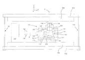
- FIG. 4 is partial cross-sectional side view of the blind mate connector assembly of FIGS. 1-3 positioned between a pair of electronic assemblies according to one example of the present disclosure.
- FIG. 5 is partial top view of a right portion of the blind mate connector assembly of FIG. 2 according to one example of the present disclosure.
- the term “substantially” refers to the complete or nearly complete extent or degree of an action, characteristic, property, state, structure, item, or result.
- an object that is “substantially” enclosed would mean that the object is either completely enclosed or nearly completely enclosed.
- the exact allowable degree of deviation from absolute completeness may in some cases depend on the specific context. However, generally speaking the nearness of completion will be so as to have the same overall result as if absolute and total completion were obtained.
- the use of “substantially” is equally applicable when used in a negative connotation to refer to the complete or near complete lack of an action, characteristic, property, state, structure, item, or result.
- adjacent refers to the proximity of two structures or elements. Particularly, elements that are identified as being “adjacent” may be either abutting or connected. Such elements may also be near or close to each other without necessarily contacting each other. The exact degree of proximity may in some cases depend on the specific context.
- a cable connector housing for blind mate connection of a right angle cable connector to an electronics assembly.
- the cable connector housing comprises a housing body and a connector cavity formed within the housing body and configured to receive and retain a right angle cable connector.
- a first opening is formed through the housing body and extends to the connector cavity and has a central axis and is sized to receive a blind mate connecting portion of the right angle cable connector.
- a second opening is formed through the housing body and extends to the connector cavity.
- the second opening has a central axis and is sized to receive a cable line connected to the right angle cable connector.
- the central axes of the first and second openings are oriented orthogonal to one another.
- the cable connector housing comprises a mechanical float mechanism configured to facilitate movement of the right angle cable connector relative to the connector cavity and the housing body in multiple degrees of freedom.
- a blind mate connector assembly comprising a first manifold comprising a plurality of first openings each having a central axis, and a second manifold removably coupled to the first manifold to define a connector housing positionable between a primary electronics assembly and a secondary electronics assembly.
- the second manifold comprises a plurality of second openings each having a central axis.
- a plurality of connector cavities defined by the first and second manifolds.
- a plurality of right angle cable connectors each situated within one of the plurality of connector cavities, and the right angle cable connectors facilitate blind mate connection between the primary electronics assembly and the secondary electronics assembly.
- the connector housing comprises a mechanical float mechanism configured to facilitate movement of the right angle cable connector relative to the connector cavity and the housing body in multiple degrees of freedom.
- an electronics system comprising a primary electronics assembly and a secondary electronics assembly mechanically and electrically coupled to each other.
- a blind mate connector assembly coupled between the primary electronics assembly and the secondary electronics assembly comprises a housing removably attached to the primary electronics assembly.
- the housing has a plurality of connector cavities.
- a plurality of cables each comprises a cable connector and a cable line extending from the cable connector.
- Each cable line is electrically coupled to the primary electronics assembly, and each cable connector is removably positioned within one of the plurality of connector cavities and blind mate connected to the secondary electronics assembly.
- the housing comprises a mechanical float mechanism configured to facilitate movement of the right angle cable connector relative to the connector cavity and the housing body in multiple degrees of freedom.
- FIGS. 1-5 illustrate various views of an electronics system 100 according to one example.
- the electronics system 100 can comprise a blind mate connector assembly 102 positioned between a primary electronics assembly 104 and a secondary electronics assembly 106 to facilitate a blind mate (mechanical and electrical) connection between the primary and secondary electronics assemblies 104 and 106 .
- the primary and secondary electronics assemblies 104 and 106 can each be a circuit card assembly (CCA) having a plurality of electrical and mechanical components supported on a substrate.
- the primary electronics assembly 104 can have a first electrical coupling 108 that blind mate interfaces with a second electrical coupling 110 on the secondary electronics assembly 106 .
- Such blind mate interface can be a power and control connection between blind mated CCAs, for instance.
- this connection can limit the amount of relative realignment required for another blind mate connection, such as for RF connections.
- a number of dielectric panels can be provided to mechanically couple (i.e., sandwich together) the primary and secondary electronics assemblies 104 and 106 together to form a low-profile electronics system.
- the panels can have fasteners that mechanically coupled the primary and secondary electronics 104 and 106 together via their substrates in a typical manner. When such panels and CCAs are sandwiched/attached together, for example, this can form a digital receiver module (DRM) used on Ku radio frequency systems (KRFS) as a part of an array back end unit (ABEU).
- DRM digital receiver module
- KRFS Ku radio frequency systems
- ABEU array back end unit
- FIG. 4 shows the primary electronics assembly 104 generally parallel to secondary electronics assembly 106 and attached together between upper and lower panels 112 and 114 , which can be attached to each other with fasteners 116 , as known in the art.
- Other fasteners can couple respective panels 112 and 114 to the primary and secondary electronics assemblies 104 and 106 .
- the blind mate connector assembly 102 can be positioned between the primary and secondary electronics assembly 104 and 106 to facilitate a blind mate connection between the primary and secondary electronics assemblies 104 and 106 .
- the blind mate connector assembly 102 can comprise a first manifold 120 that is removably coupled to a second manifold 122 to collectively form a connector housing body, for instance.
- a plurality of fasteners 124 are each positioned through respective apertures of the second manifold 122 , as shown, and attached to receiving threads of the first manifold 120 .
- These coupled first and second manifolds 120 and 122 can be removably attached to the first electronics assembly 104 using a pair of fasteners 126 (e.g., machine screws) disposed through apertures of the first electronics assembly 104 .
- the fasteners 126 can be attached to receiving threads on either end of the first manifold 120 . See also the partial cross sectional view FIG. 4 for the coupling interface between the first and second manifolds 120 and 122 .
- the first and second manifolds 120 and 122 are mated to each other and attached to the primary electronics assembly 104 .
- a plurality of cables 128 can electrically couple the primary electronics assembly 104 to the secondary electronics assembly 106 .
- a particular cable line 130 e.g., coaxial cable
- a multi-contact device 133 can be a commercially available multi-contact RF module (or other backplane RF connector) attached to the primary electronics assembly 104 .
- Such multi-contact device 133 can removably receive connector ends (not shown) of the cable lines 130 , and therefore can electrically couple transmission of RF signals between the primary and secondary electronics assemblies 104 and 106 , for example.
- the plurality of cables 128 can be commercially available as right angle coaxial cables that have connectors, such as SMPM connectors, SMP connectors, or similar connectors. However, this is not intended to be limiting in any way.
- a blind mate connecting portion 134 of each cable connector 132 e.g., a right angle connector
- At least one “mechanical float mechanism” can be provided by the configuration of the blind mate connector assembly 102 to facilitate movement of the cable connector 132 in multiple degrees of freedom relative to the first and second manifolds 120 and 122 (and consequently relative to the assemblies 104 and 106 ). More specifically, and as illustrated in FIG. 4 , when the first and second manifolds 120 and 122 are coupled together, a plurality of connector cavities 137 can be formed to retain each respective cable connector 132 .
- the perimeter walls of the connector cavity 137 (defined by recesses/cavities in each of the first and second manifolds 120 and 122 ) can be formed to be spatially separated away from the cable connector 132 , meaning that the connector cavity 137 is sized larger than the cable connector 132 , such that it “loosely” retains the cable connector 132 to allow relative movement of the cable connector 132 within its particular connector cavity 137 .
- This is one example of a “mechanical float mechanism” that facilitates some movement of the cable connector 132 while the secondary electronics assembly 106 is being blind mate connected to the primary secondary electronics assembly 104 . This can account for tolerances that can cause misalignment between the primary and secondary electronic assemblies 104 and 106 when being blind mate coupled together.
- each of the plurality of cable connectors 132 can be configured and permitted to move a certain degree within the respective connector cavity 137 so that each and every cable connector 132 (e.g., 8 total in this example) can be simultaneously blind mate connected to respective blind mate receiving portions 136 along the secondary electronics assembly 106 .
- Such blind mate interface e.g., of 134 and 136
- Such interface can comprise a press-fit or friction-fit interface that can be achieved with between one and five pounds of force, for instance.
- the cable connector 132 can be allowed to move in the x and/or y directions relative to the first and second manifolds 120 and 122 . This can also account for misalignment between the primary and secondary assemblies 104 and 106 when being blind mate connected to each other.
- the first manifold 120 can comprises a plurality of first openings 138 (e.g., 8 shown on FIG. 1 ), each having a central axis A along the z axis, which is best shown in FIG. 4 .
- Each first opening 138 can be sized larger than the blind mate receiving portion 134 of the cable connector 132 , such that the blind mate receiving portion 134 can be spatially separated from the edges defined by the first opening 138 so that the cable connector 132 can freely move about the first opening 138 .
- This is also illustrated by the top-down view of FIG. 5 , showing three blind mate connecting portions 134 loosely received by respective first openings 138 of the first manifold 120 .
- This configuration allows the cable connector 132 to move (axially and/or radially) about the first opening 138 when the blind mate receiving portion 136 (of the second electronic assembly 106 ) locates and receives the blind mate connecting portion 134 during blind mate coupling.
- Each first opening 138 having these “oversized holes” also works in conjunction with the connector cavities 137 loosely receiving each cable connector 132 to allow multiple degrees of movement of the cable connectors 132 within their respective connector cavities 137 .
- the cable line 130 (e.g., a coaxial cable line) can be allowed to move relative to the first and second manifolds 120 and 122 to account for misalignment (e.g., radial) between the primary and secondary electronics assemblies 104 and 106 when blind mate coupled to each other.
- the first manifold 120 can comprise a plurality of recesses 140 formed along a lower edge of the first manifold 120 and that can be in fluid or volumetric communication with the respective connector cavity 137 (see FIGS. 1, 2, and 4 ).
- the second manifold 122 can comprise a plurality of recesses 142 formed along an upper edge of the second manifold 122 at locations corresponding to the recesses 140 of the first manifold 120 .
- each recess 140 and each (corresponding) recess 142 can form a second opening 144 through which a particular cable line 30 can pass or extend. See FIG. 4 specifically for an example arrangement of the cable line 30 extending loosely through the second opening 144 .
- the mechanical float mechanism in this example can be defined by the second opening 144 being sized larger than the cable line 130 so that the second opening 144 loosely retains a portion of the cable line 130 .
- the central axis A of the first opening 138 can be transverse (e.g., in some examples orthogonal or perpendicular) to a central axis B of the second opening 144 .
- Such configuration assists to properly retain and appropriately position the cable 128 between the first and second manifolds 120 and 122 so that the blind mate connecting portions 134 can extend through respective first openings 138 as the cable lines 130 extend through respective second openings 144 .
- a spring 146 (or other biasing device) can be situated within the connector cavity 137 and configured to bias each cable connector 132 in a z direction (as shown in the drawings) along the respective central axis A of the first opening 138 toward the secondary electronics assembly 106 .
- the spring 146 can be one or more compliant dielectric/EMI strips, or the spring can be individual leaf springs or compression springs or O-rings positioned below each of the cable connectors 132 .
- each spring 146 (being illustrated as a pair of compliant strips) can each be retained within and along a respective groove 148 formed in the second manifold 122 .
- the grooves 148 can interconnect the plurality of cavities 137 , as shown in FIG. 3 .
- the grooves 148 can be formed laterally along a length of the second manifold 122 in a manner that positions a portion of each spring 146 directly below a corresponding cable connector 132 , and along the central axis A of each first opening 138 (see FIG. 4 ).
- the spring 146 can be slightly compressed, which causes an upward biasing force (in the z direction) to assist with completing the blind mate (friction-fit) interface between the blind mate receiving portion 136 and the blind mate connecting portion 134 .
- all of the cable connectors 132 can be simultaneously blind mated to respective blind mate receiving portions 136 of the secondary electronics assembly 106 .
- the spring 146 can also allow for some amount of rotational movement of the cable connector 132 so that it may freely move in the x and/or y directions (laterally and/or radially) about the first opening 138 until the cable connector 132 is blind mated into its respective blind mate receiving portion 136 .
- the first and second manifolds 120 and 122 can be removed from the primary electronics assembly 104 by removing fasteners 126 (after the secondary electronics assembly 106 is detached from the primary electronics assembly 104 ).
- the second manifold 122 can be detached from the first manifold 120 by removing fasteners 124 , which then exposes the cable connectors 132 of the cables 128 .
- one or more cables 128 can be removed and replaced, and then the first and second manifolds 120 and 122 can be reattached to each other and then reattached to the primary electronics assembly 104 .
- the first manifold 120 can have downwardly formed protrusions 115 on either end that are biased to the first electronics assembly 104 when attached thereto.
- This configuration positions the second manifold 122 above and away from the first electronics assembly 104 to avoid any unwanted electrical contact to the primary electronics assembly 104 with the fasteners 124 and/or cable lines 130 .
- the first and second manifolds 120 and 122 can be comprised of a rigid dielectric material, such as polymer or plastic.
Landscapes
- Connector Housings Or Holding Contact Members (AREA)
Priority Applications (4)
| Application Number | Priority Date | Filing Date | Title |
|---|---|---|---|
| US15/459,295 US10243301B2 (en) | 2017-03-15 | 2017-03-15 | Blind mate connector housing and assembly |
| EP22178991.0A EP4113752B1 (de) | 2017-03-15 | 2018-01-12 | Blindstecker anordnung und elektroniksystem |
| PCT/US2018/013613 WO2018169598A1 (en) | 2017-03-15 | 2018-01-12 | Blind mate connector housing and assembly |
| EP18709157.4A EP3596785B1 (de) | 2017-03-15 | 2018-01-12 | Blindsteckergehäuse und elektroniksystem |
Applications Claiming Priority (1)
| Application Number | Priority Date | Filing Date | Title |
|---|---|---|---|
| US15/459,295 US10243301B2 (en) | 2017-03-15 | 2017-03-15 | Blind mate connector housing and assembly |
Publications (2)
| Publication Number | Publication Date |
|---|---|
| US20180269629A1 US20180269629A1 (en) | 2018-09-20 |
| US10243301B2 true US10243301B2 (en) | 2019-03-26 |
Family
ID=61569379
Family Applications (1)
| Application Number | Title | Priority Date | Filing Date |
|---|---|---|---|
| US15/459,295 Active US10243301B2 (en) | 2017-03-15 | 2017-03-15 | Blind mate connector housing and assembly |
Country Status (3)
| Country | Link |
|---|---|
| US (1) | US10243301B2 (de) |
| EP (2) | EP3596785B1 (de) |
| WO (1) | WO2018169598A1 (de) |
Cited By (1)
| Publication number | Priority date | Publication date | Assignee | Title |
|---|---|---|---|---|
| WO2025109055A1 (de) * | 2023-11-21 | 2025-05-30 | Hirschmann Automotive Gmbh | Steckverbinder mit einem schwimmenden kontaktträger |
Families Citing this family (4)
| Publication number | Priority date | Publication date | Assignee | Title |
|---|---|---|---|---|
| US10566722B2 (en) * | 2018-07-18 | 2020-02-18 | Getac Technology Corporation | Float-type connecting module and float-type docking device having the module |
| CN110247354B (zh) * | 2018-10-17 | 2023-11-24 | 广州番禺电缆集团有限公司 | 一种浮动式限位器 |
| JP7435048B2 (ja) * | 2019-05-10 | 2024-02-21 | 株式会社オートネットワーク技術研究所 | 接続装置およびコネクタ |
| US11399448B1 (en) * | 2021-02-25 | 2022-07-26 | Baidu Usa Llc | Full server liquid system auto-connecting design |
Citations (11)
| Publication number | Priority date | Publication date | Assignee | Title |
|---|---|---|---|---|
| US4892491A (en) * | 1988-12-19 | 1990-01-09 | Motorola, Inc. | Coaxial connector |
| US5676569A (en) * | 1996-07-25 | 1997-10-14 | The Whitaker Corporation | Holder for several electrical connectors |
| US6700464B2 (en) | 2002-02-21 | 2004-03-02 | Intel Corporation | Low cost high speed board-to-board coaxial connector design with co-planar waveguide for PCB launch |
| US20060084286A1 (en) | 2004-10-14 | 2006-04-20 | Kooiman John A | Multiple-position push-on electrical connector |
| US7118383B2 (en) | 2004-07-27 | 2006-10-10 | Hosiden Corporation | Coaxial connector for board-to-board connection |
| CN201438524U (zh) | 2009-08-06 | 2010-04-14 | 深圳速联连接器有限公司 | 板对板连接器 |
| EP2208259A1 (de) | 2007-11-07 | 2010-07-21 | Multi-Holding AG | Stecker und steckverbindung für roboter |
| US8002574B1 (en) | 2010-11-04 | 2011-08-23 | Tyco Electronics Corporation | RF module with a housing with spring loaded connectors and a strain relief extending rearward of the housing |
| US8137134B1 (en) * | 2010-11-29 | 2012-03-20 | Ezconn Corporation | Coaxial cable connector with an insulating member with a bendable section with a pair of projections |
| CN203589316U (zh) | 2013-09-26 | 2014-05-07 | 鲁建文 | 一种板到板射频同轴连接器的外壳结构 |
| EP3043425A1 (de) * | 2015-01-12 | 2016-07-13 | Amphenol Corporation | Schwimmeradapter für elektrischen verbinder |
Family Cites Families (2)
| Publication number | Priority date | Publication date | Assignee | Title |
|---|---|---|---|---|
| US8029324B1 (en) * | 2010-11-04 | 2011-10-04 | Tyco Electronics Corporation | RF connector assembly |
| US8360806B2 (en) * | 2010-12-22 | 2013-01-29 | Tyco Electronics Corporation | RF module |
-
2017
- 2017-03-15 US US15/459,295 patent/US10243301B2/en active Active
-
2018
- 2018-01-12 EP EP18709157.4A patent/EP3596785B1/de active Active
- 2018-01-12 EP EP22178991.0A patent/EP4113752B1/de active Active
- 2018-01-12 WO PCT/US2018/013613 patent/WO2018169598A1/en not_active Ceased
Patent Citations (11)
| Publication number | Priority date | Publication date | Assignee | Title |
|---|---|---|---|---|
| US4892491A (en) * | 1988-12-19 | 1990-01-09 | Motorola, Inc. | Coaxial connector |
| US5676569A (en) * | 1996-07-25 | 1997-10-14 | The Whitaker Corporation | Holder for several electrical connectors |
| US6700464B2 (en) | 2002-02-21 | 2004-03-02 | Intel Corporation | Low cost high speed board-to-board coaxial connector design with co-planar waveguide for PCB launch |
| US7118383B2 (en) | 2004-07-27 | 2006-10-10 | Hosiden Corporation | Coaxial connector for board-to-board connection |
| US20060084286A1 (en) | 2004-10-14 | 2006-04-20 | Kooiman John A | Multiple-position push-on electrical connector |
| EP2208259A1 (de) | 2007-11-07 | 2010-07-21 | Multi-Holding AG | Stecker und steckverbindung für roboter |
| CN201438524U (zh) | 2009-08-06 | 2010-04-14 | 深圳速联连接器有限公司 | 板对板连接器 |
| US8002574B1 (en) | 2010-11-04 | 2011-08-23 | Tyco Electronics Corporation | RF module with a housing with spring loaded connectors and a strain relief extending rearward of the housing |
| US8137134B1 (en) * | 2010-11-29 | 2012-03-20 | Ezconn Corporation | Coaxial cable connector with an insulating member with a bendable section with a pair of projections |
| CN203589316U (zh) | 2013-09-26 | 2014-05-07 | 鲁建文 | 一种板到板射频同轴连接器的外壳结构 |
| EP3043425A1 (de) * | 2015-01-12 | 2016-07-13 | Amphenol Corporation | Schwimmeradapter für elektrischen verbinder |
Non-Patent Citations (1)
| Title |
|---|
| International Search Report for International Application No. PCT/US2018/013613 dated May 16, 2018, 14 pages. |
Cited By (1)
| Publication number | Priority date | Publication date | Assignee | Title |
|---|---|---|---|---|
| WO2025109055A1 (de) * | 2023-11-21 | 2025-05-30 | Hirschmann Automotive Gmbh | Steckverbinder mit einem schwimmenden kontaktträger |
Also Published As
| Publication number | Publication date |
|---|---|
| EP3596785B1 (de) | 2022-06-15 |
| EP4113752A1 (de) | 2023-01-04 |
| WO2018169598A1 (en) | 2018-09-20 |
| EP3596785A1 (de) | 2020-01-22 |
| EP4113752B1 (de) | 2024-07-03 |
| US20180269629A1 (en) | 2018-09-20 |
Similar Documents
| Publication | Publication Date | Title |
|---|---|---|
| US10243301B2 (en) | Blind mate connector housing and assembly | |
| US11056807B2 (en) | Float connector for interconnecting printed circuit boards | |
| EP3254341B1 (de) | Elektrischer verbinder mit verriegelungsanordnung | |
| US7740489B2 (en) | Connector assembly having a compressive coupling member | |
| EP0720254A2 (de) | Selbstausrichtender Verbinder für eine flexible Schaltung | |
| US20160308309A1 (en) | High density electrical connector with shield plate louvers | |
| CN108475860A (zh) | 具有多个同轴触头的同轴连接器组件和通信系统 | |
| US8851934B2 (en) | Electrical module housing | |
| US7907419B2 (en) | Guide receptacle for tandem circuit board mating | |
| US7479017B1 (en) | Right angle electrical connector | |
| US8684610B2 (en) | Connector assemblies having actuation mechanisms for selectively moving mating connectors | |
| EP3467950B1 (de) | Verbinder | |
| US8292644B2 (en) | Connector assembly having a floating mating array | |
| CN106558782B (zh) | 互连设备 | |
| MX2014012628A (es) | Ensamble de conector de cables y charolas de cables que tiene un conector de cables flotante. | |
| CN115810955A (zh) | 一种连接器及使用该连接器的连接器组件 | |
| US20120088410A1 (en) | Connector and semiconductor testing device including the connector | |
| US6860028B2 (en) | Alignment device and method of connecting a circuit card to a mid plane | |
| US8758055B2 (en) | RF module | |
| US10431914B2 (en) | Network connector assembly | |
| US10050361B1 (en) | Flexible circuit connector | |
| KR200492776Y1 (ko) | 커넥터 | |
| US8721189B2 (en) | Optical fiber connector assembly | |
| US9653861B2 (en) | Interconnection of hardware components | |
| CN114335935A (zh) | 介质滤波器 |
Legal Events
| Date | Code | Title | Description |
|---|---|---|---|
| AS | Assignment |
Owner name: RAYTHEON COMPANY, MASSACHUSETTS Free format text: ASSIGNMENT OF ASSIGNORS INTEREST;ASSIGNORS:BERNARD, ROBERT P.;PRUETT, JAMES A.;REEL/FRAME:041581/0354 Effective date: 20170314 |
|
| STCF | Information on status: patent grant |
Free format text: PATENTED CASE |
|
| MAFP | Maintenance fee payment |
Free format text: PAYMENT OF MAINTENANCE FEE, 4TH YEAR, LARGE ENTITY (ORIGINAL EVENT CODE: M1551); ENTITY STATUS OF PATENT OWNER: LARGE ENTITY Year of fee payment: 4 |