US1024003A - Bleaching and dyeing machine. - Google Patents
Bleaching and dyeing machine. Download PDFInfo
- Publication number
- US1024003A US1024003A US53673510A US1910536735A US1024003A US 1024003 A US1024003 A US 1024003A US 53673510 A US53673510 A US 53673510A US 1910536735 A US1910536735 A US 1910536735A US 1024003 A US1024003 A US 1024003A
- Authority
- US
- United States
- Prior art keywords
- vat
- dye
- dyeing
- pipes
- machine
- Prior art date
- Legal status (The legal status is an assumption and is not a legal conclusion. Google has not performed a legal analysis and makes no representation as to the accuracy of the status listed.)
- Expired - Lifetime
Links
- 238000004043 dyeing Methods 0.000 title description 17
- 238000004061 bleaching Methods 0.000 title description 4
- 239000000975 dye Substances 0.000 description 21
- 239000007788 liquid Substances 0.000 description 7
- 238000010438 heat treatment Methods 0.000 description 6
- 239000000463 material Substances 0.000 description 3
- XEEYBQQBJWHFJM-UHFFFAOYSA-N Iron Chemical compound [Fe] XEEYBQQBJWHFJM-UHFFFAOYSA-N 0.000 description 2
- 239000004568 cement Substances 0.000 description 1
- 238000010276 construction Methods 0.000 description 1
- 229910052742 iron Inorganic materials 0.000 description 1
- 239000000203 mixture Substances 0.000 description 1
- 230000004048 modification Effects 0.000 description 1
- 238000012986 modification Methods 0.000 description 1
- 238000005192 partition Methods 0.000 description 1
- 239000000126 substance Substances 0.000 description 1
- 239000002023 wood Substances 0.000 description 1
Images

Classifications
-
- D—TEXTILES; PAPER
- D06—TREATMENT OF TEXTILES OR THE LIKE; LAUNDERING; FLEXIBLE MATERIALS NOT OTHERWISE PROVIDED FOR
- D06B—TREATING TEXTILE MATERIALS USING LIQUIDS, GASES OR VAPOURS
- D06B5/00—Forcing liquids, gases or vapours through textile materials to effect treatment, e.g. washing, dyeing, bleaching, sizing impregnating
- D06B5/12—Forcing liquids, gases or vapours through textile materials to effect treatment, e.g. washing, dyeing, bleaching, sizing impregnating through materials of definite length
- D06B5/16—Forcing liquids, gases or vapours through textile materials to effect treatment, e.g. washing, dyeing, bleaching, sizing impregnating through materials of definite length through yarns, threads or filaments
- D06B5/20—Forcing liquids, gases or vapours through textile materials to effect treatment, e.g. washing, dyeing, bleaching, sizing impregnating through materials of definite length through yarns, threads or filaments through hanks
Definitions
- My invention relates to improvements in bleaching and dyeing machines, and more particularly to such machines of the open type adapted for the dyeing of silk yarns.
- the main object of the present invention is the construction of a simple and efficient machine which brings about the even circulation of the dyeing solution in the dyeing vat at an even temperature and without the direct application of steam or raw dye stuff in the dyeing vat itself. This results in a uniform dyeing of the material under treatment.
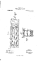
- FIG. 1 is a longitudinal section
- Fig. 2 is a plan of the vat and steam chamber
- Fig. 3 is a cross section on the line 33 of Fig. 1
- Fig. 4 is a diagrammatic view of the entire apparatus including the pump required to operate the same together with its connections.
- A indicates the vat having an enlarged upper portion B forming a ledge C around the top of but outside the main walls of the vat.
- a system of pipes D which communicate with the interior of the vat through a very large number of orifices E.
- the pipe system F which is also provided with a large number of orifices.
- the false bottom G is also provided with a large number of perforations.
- the frame H which carries the yarn I.
- the frame H is shown as a double frame adapted to hold the yarn both at its upper portion and in its lower portion, as shown. The frame is lifted into or out of operation by means of the chain and ring J.
- the mixing and heating chamber K communicates at its upper portion with the pipe system F of the vat by means of the connections F.
- the steam pipes L having numerous perforations and by means of which the mixing of the dye as well as the heating to the proper temperature is accomplished.
- a thermometer M indicates the heat of the mixture in the chamber K.
- the top of the mixing chamber K has a hinged portion P which carries a spout Q, for the introduction of the raw dye materials.
- the operation of the machine is as follows: After the dyeing liquid has been mixed and heated to the required temperature in the chamber K, and the vat A has been filled with liquid dye, the frame H carrying the yarn is set into the vat. When the dyeing liquid in the vat A rises above the level of the apertures in the pipe F, the dye flows through said pipes F into the mixing chamber K where fresh dye stud may be added and heat applied to the proper degree of temperature. A partition R compels the dyeing liquid in its travel from N to F to flow downwardly over the steam pipes L. The pump forces the dye stuff which has been thus prepared in the chamber K into the pipe system D from which the dye immerges at a uniform heat and in a very large number of small streams into the body of the dyeing liquid in the vat.
- substantially the entire volume inclosed by the wall of the vat may be used for dyeing purposes; that no direct heat is applied in the dyeing vat, and; that the circulation of the dye in the vat is maintained at a substantially uniform temperature in the chamber K.
- a vat a system of pipes within said vat having a large number of apertures and adapted to introduce dye into the vat, another system of pipes within said vat having a large number of apertures for removing dye from the vat, an auX- iliary dye chamber connected with each of said pipe systems, means for introducing steam into said chamber, and means for circulating the dye through the chamber and the two pipe systems, substantially as and for the purpose described.
- a vat a system of perforated pipes at the bottom of said vat, another system of perforated pipes at the top of said vat, a frame for carrying the yarn, a dye mixing and heating chamber connected with each of said pipe systems, and means for circulating the dye through said chamber and the two pipe systems, substantially as and for the purpose described.
- a vat with an enlarged upper portion a system of perforated pipes within said upper portion and outside the main walls of the vat, a system of perforated pipes at the bottom of said vat, a frame for carrying the yarn, means for lowering said frame into and raising itfrom said vat, and means for circulating the dye through said vat between the two pipe systems, substantially as and for the purpose described.
Landscapes
- Engineering & Computer Science (AREA)
- Chemical & Material Sciences (AREA)
- Materials Engineering (AREA)
- Textile Engineering (AREA)
- Treatment Of Fiber Materials (AREA)
- Coloring (AREA)
Description
T. FRUSHER. BLEAGHING AND DYBING MACHINE.
APPLICATION FILED JAN. 6, 1910.
Patented Apr. 23, 1912.
2 SHEETS-BHEET 2.
INVEA/ TOR WITNESSES:
TOM F/PUSHE/P ATTORNEYS I COLUMBIA PLANOGRAPH CD-IWASHINGTON. 11:.
UNITED STTS BLEACI-IING- AND DYEING MACHINE.
Specification of Letters Patent.
Patented Apr. 23, 1912.
Application filed January 6, 1910. Serial No. 536,735.
To (ZZZ whom it may concern Be it known that I, Torr FRUsrruR, a subject of the King of Great Britain, residing at 34 Plaza street, Brooklyn, city, county, and State of New York, have invented certain new and useful Improvements in Bleaching and Dyeing Machines, of which the following is a specification.
My invention relates to improvements in bleaching and dyeing machines, and more particularly to such machines of the open type adapted for the dyeing of silk yarns.
The main object of the present invention is the construction of a simple and efficient machine which brings about the even circulation of the dyeing solution in the dyeing vat at an even temperature and without the direct application of steam or raw dye stuff in the dyeing vat itself. This results in a uniform dyeing of the material under treatment.
The machine is illustrated in the accompanying drawings, in which Figure 1 is a longitudinal section; Fig. 2 is a plan of the vat and steam chamber; Fig. 3 is a cross section on the line 33 of Fig. 1: Fig. 4 is a diagrammatic view of the entire apparatus including the pump required to operate the same together with its connections.
A indicates the vat having an enlarged upper portion B forming a ledge C around the top of but outside the main walls of the vat. Upon the bottom of the vat there is arranged a system of pipes D-which communicate with the interior of the vat through a very large number of orifices E. Upon the ledge C rests the pipe system F, which is also provided with a large number of orifices. Above the pipe system D is placed the false bottom G, also provided with a large number of perforations. Set upon this false bottom G is the frame H which carries the yarn I. The frame H is shown as a double frame adapted to hold the yarn both at its upper portion and in its lower portion, as shown. The frame is lifted into or out of operation by means of the chain and ring J. The mixing and heating chamber K communicates at its upper portion with the pipe system F of the vat by means of the connections F. In the lower portion of this mixing chamber K there are introduced the steam pipes L having numerous perforations and by means of which the mixing of the dye as well as the heating to the proper temperature is accomplished. A thermometer M indicates the heat of the mixture in the chamber K.
The chamber K at some point below the level of the pipe F communicates by means of the pipe system N with a pump which forces the liquid through the pipe system mto the perforated pipe D of the vat; the three-way valves N and 0 control the two systems N and O. The top of the mixing chamber K has a hinged portion P which carries a spout Q, for the introduction of the raw dye materials.
The operation of the machine is as follows: After the dyeing liquid has been mixed and heated to the required temperature in the chamber K, and the vat A has been filled with liquid dye, the frame H carrying the yarn is set into the vat. When the dyeing liquid in the vat A rises above the level of the apertures in the pipe F, the dye flows through said pipes F into the mixing chamber K where fresh dye stud may be added and heat applied to the proper degree of temperature. A partition R compels the dyeing liquid in its travel from N to F to flow downwardly over the steam pipes L. The pump forces the dye stuff which has been thus prepared in the chamber K into the pipe system D from which the dye immerges at a uniform heat and in a very large number of small streams into the body of the dyeing liquid in the vat. This causes a uniform condition of heat, of color and of circulation in the vat, which is highly desirable and the essence of this invention. The withdrawal of the dye as it rises in the vat through the apertures in the pipes F and consequently at a very large number of places at once, prevents any currents or definite direction of circulation of the dye in the vat. Yarn dyed in this machine will be smoothly and evenly dyed. After the yarn has been dyed as above described, the operation may be reversed by proper control of the valves 0 and N so that the fresh dyeing liquid enters into the vat by way of the upper pipe system F and is withdrawn through the lower pipe system D. The false bottom Gr when used, serves to distribute the dye stuff in a uniform and even manner similar to that when the pipes alone are used without the false bottom.
From the above description it will be seen that the machine is extremely simple;
that substantially the entire volume inclosed by the wall of the vat may be used for dyeing purposes; that no direct heat is applied in the dyeing vat, and; that the circulation of the dye in the vat is maintained at a substantially uniform temperature in the chamber K.
Various modifications may be made without departing from the spirit of my invention and the various parts may be made of any suitable material, that is, of wood, iron, cement or the like, according to the nature of the chemicals used in the dyeing, bleaching or such other kindred use to which such machine is put.
I claim as my invention:
1. In a machine of the class described, the combination of a vat, a system of perforated pipes at the bottom of said vat, another system of perforated pipes at the top of said vat and apparatus connected with each of said systems but outside said vat for heating, mixing and circulating the dye, substantially as and for the purpose described.
2. In a machine of the class described, the combination of a vat, oppositely located systems of perforated pipes within said vat, and apparatus connected with each of said systems but outside of said vat for heating, mixing and circulating the dye, substantially as and for the purpose described.
3. In a machine of the class described, the combination of a vat, a system of pipes within said vat having a large number of apertures and adapted to introduce dye into the vat, another system of pipes within said vat having a large number of apertures for removing dye from the vat, an auX- iliary dye chamber connected with each of said pipe systems, means for introducing steam into said chamber, and means for circulating the dye through the chamber and the two pipe systems, substantially as and for the purpose described.
4. In a machine of the class described, the combination of a vat, a series of perforated pipes located at the bottom of said vat and a series of perforated pipes located at the top of said vat so as to include a free space between said pipes and means connecting the two series of pipes and comprising a mixing and heating chamber and a circulating pump.
5. In a machine of the class described, the combination. of a vat, a system of perforated pipes at the bottom of said vat, another system of perforated pipes at the top of said vat, a frame for carrying the yarn, a dye mixing and heating chamber connected with each of said pipe systems, and means for circulating the dye through said chamber and the two pipe systems, substantially as and for the purpose described.
6. In a machine of the class described, the combination of a vat with an enlarged upper portion, a system of perforated pipes within said upper portion and outside the main walls of the vat, a system of perforated pipes at the bottom of said vat, a frame for carrying the yarn, means for lowering said frame into and raising itfrom said vat, and means for circulating the dye through said vat between the two pipe systems, substantially as and for the purpose described.
In testimony whereof I have hereunto set my hand in the presence of two subscribing witnesses.
TOM FRUSHER. Witnesses ELMER G. IVILLYOUNG, G. V. RASMUSSEN.
Copies of this patent may be obtained for five cents each, by addressing the Commissioner of Patents, Washington, I). C.
Priority Applications (1)
| Application Number | Priority Date | Filing Date | Title |
|---|---|---|---|
| US53673510A US1024003A (en) | 1910-01-06 | 1910-01-06 | Bleaching and dyeing machine. |
Applications Claiming Priority (1)
| Application Number | Priority Date | Filing Date | Title |
|---|---|---|---|
| US53673510A US1024003A (en) | 1910-01-06 | 1910-01-06 | Bleaching and dyeing machine. |
Publications (1)
| Publication Number | Publication Date |
|---|---|
| US1024003A true US1024003A (en) | 1912-04-23 |
Family
ID=3092299
Family Applications (1)
| Application Number | Title | Priority Date | Filing Date |
|---|---|---|---|
| US53673510A Expired - Lifetime US1024003A (en) | 1910-01-06 | 1910-01-06 | Bleaching and dyeing machine. |
Country Status (1)
| Country | Link |
|---|---|
| US (1) | US1024003A (en) |
-
1910
- 1910-01-06 US US53673510A patent/US1024003A/en not_active Expired - Lifetime
Similar Documents
| Publication | Publication Date | Title |
|---|---|---|
| US1024003A (en) | Bleaching and dyeing machine. | |
| US3616663A (en) | Apparatus for dyeing cloth | |
| US1400675A (en) | Process of dyeing yarns and the like | |
| US755050A (en) | Apparatus for dyeing, &c. | |
| US1265332A (en) | Beam dyeing-machine. | |
| US1271549A (en) | Dyeing-machine. | |
| US362620A (en) | hauschel | |
| US428614A (en) | Dyeing apparatus | |
| US1254006A (en) | Dyeing apparatus. | |
| US1269934A (en) | Beam dyeing-machine. | |
| US332740A (en) | Julius otto obeemaiee | |
| US410744A (en) | Apparatus for dyeing | |
| US2308784A (en) | Apparatus for dyeing wool | |
| US333876A (en) | William mather | |
| US446050A (en) | Apparatus for dyeing straw goods | |
| US1389444A (en) | grundy | |
| US323819A (en) | William mather | |
| US665646A (en) | Dye-vat. | |
| US715719A (en) | Apparatus for dyeing. | |
| US1576378A (en) | Dyeing apparatus | |
| US892898A (en) | Dyeing and bleaching apparatus. | |
| US764966A (en) | Apparatus for dyeing. | |
| US1868513A (en) | Process and apparatus for treating textile materials | |
| US425980A (en) | chambers | |
| US584902A (en) | Half to george thomas |