US10226076B2 - Disposable cartridge for use in an electronic nicotine delivery system - Google Patents
Disposable cartridge for use in an electronic nicotine delivery system Download PDFInfo
- Publication number
- US10226076B2 US10226076B2 US15/525,640 US201515525640A US10226076B2 US 10226076 B2 US10226076 B2 US 10226076B2 US 201515525640 A US201515525640 A US 201515525640A US 10226076 B2 US10226076 B2 US 10226076B2
- Authority
- US
- United States
- Prior art keywords
- disposable cartridge
- nicotine
- electric heater
- reservoir
- port
- Prior art date
- Legal status (The legal status is an assumption and is not a legal conclusion. Google has not performed a legal analysis and makes no representation as to the accuracy of the status listed.)
- Expired - Fee Related
Links
Images


Classifications
-
- A24F47/008—
-
- A—HUMAN NECESSITIES
- A24—TOBACCO; CIGARS; CIGARETTES; SIMULATED SMOKING DEVICES; SMOKERS' REQUISITES
- A24F—SMOKERS' REQUISITES; MATCH BOXES; SIMULATED SMOKING DEVICES
- A24F40/00—Electrically operated smoking devices; Component parts thereof; Manufacture thereof; Maintenance or testing thereof; Charging means specially adapted therefor
- A24F40/40—Constructional details, e.g. connection of cartridges and battery parts
- A24F40/42—Cartridges or containers for inhalable precursors
-
- A—HUMAN NECESSITIES
- A24—TOBACCO; CIGARS; CIGARETTES; SIMULATED SMOKING DEVICES; SMOKERS' REQUISITES
- A24B—MANUFACTURE OR PREPARATION OF TOBACCO FOR SMOKING OR CHEWING; TOBACCO; SNUFF
- A24B15/00—Chemical features or treatment of tobacco; Tobacco substitutes, e.g. in liquid form
- A24B15/10—Chemical features of tobacco products or tobacco substitutes
- A24B15/16—Chemical features of tobacco products or tobacco substitutes of tobacco substitutes
- A24B15/167—Chemical features of tobacco products or tobacco substitutes of tobacco substitutes in liquid or vaporisable form, e.g. liquid compositions for electronic cigarettes
-
- A—HUMAN NECESSITIES
- A24—TOBACCO; CIGARS; CIGARETTES; SIMULATED SMOKING DEVICES; SMOKERS' REQUISITES
- A24F—SMOKERS' REQUISITES; MATCH BOXES; SIMULATED SMOKING DEVICES
- A24F40/00—Electrically operated smoking devices; Component parts thereof; Manufacture thereof; Maintenance or testing thereof; Charging means specially adapted therefor
- A24F40/10—Devices using liquid inhalable precursors
-
- A—HUMAN NECESSITIES
- A24—TOBACCO; CIGARS; CIGARETTES; SIMULATED SMOKING DEVICES; SMOKERS' REQUISITES
- A24F—SMOKERS' REQUISITES; MATCH BOXES; SIMULATED SMOKING DEVICES
- A24F40/00—Electrically operated smoking devices; Component parts thereof; Manufacture thereof; Maintenance or testing thereof; Charging means specially adapted therefor
- A24F40/40—Constructional details, e.g. connection of cartridges and battery parts
- A24F40/44—Wicks
-
- A—HUMAN NECESSITIES
- A24—TOBACCO; CIGARS; CIGARETTES; SIMULATED SMOKING DEVICES; SMOKERS' REQUISITES
- A24F—SMOKERS' REQUISITES; MATCH BOXES; SIMULATED SMOKING DEVICES
- A24F40/00—Electrically operated smoking devices; Component parts thereof; Manufacture thereof; Maintenance or testing thereof; Charging means specially adapted therefor
- A24F40/40—Constructional details, e.g. connection of cartridges and battery parts
- A24F40/46—Shape or structure of electric heating means
-
- A—HUMAN NECESSITIES
- A24—TOBACCO; CIGARS; CIGARETTES; SIMULATED SMOKING DEVICES; SMOKERS' REQUISITES
- A24F—SMOKERS' REQUISITES; MATCH BOXES; SIMULATED SMOKING DEVICES
- A24F40/00—Electrically operated smoking devices; Component parts thereof; Manufacture thereof; Maintenance or testing thereof; Charging means specially adapted therefor
- A24F40/40—Constructional details, e.g. connection of cartridges and battery parts
- A24F40/48—Fluid transfer means, e.g. pumps
- A24F40/485—Valves; Apertures
-
- A—HUMAN NECESSITIES
- A24—TOBACCO; CIGARS; CIGARETTES; SIMULATED SMOKING DEVICES; SMOKERS' REQUISITES
- A24F—SMOKERS' REQUISITES; MATCH BOXES; SIMULATED SMOKING DEVICES
- A24F40/00—Electrically operated smoking devices; Component parts thereof; Manufacture thereof; Maintenance or testing thereof; Charging means specially adapted therefor
- A24F40/90—Arrangements or methods specially adapted for charging batteries thereof
-
- A—HUMAN NECESSITIES
- A24—TOBACCO; CIGARS; CIGARETTES; SIMULATED SMOKING DEVICES; SMOKERS' REQUISITES
- A24F—SMOKERS' REQUISITES; MATCH BOXES; SIMULATED SMOKING DEVICES
- A24F47/00—Smokers' requisites not otherwise provided for
-
- A—HUMAN NECESSITIES
- A61—MEDICAL OR VETERINARY SCIENCE; HYGIENE
- A61M—DEVICES FOR INTRODUCING MEDIA INTO, OR ONTO, THE BODY; DEVICES FOR TRANSDUCING BODY MEDIA OR FOR TAKING MEDIA FROM THE BODY; DEVICES FOR PRODUCING OR ENDING SLEEP OR STUPOR
- A61M15/00—Inhalators
- A61M15/06—Inhaling appliances shaped like cigars, cigarettes or pipes
-
- A—HUMAN NECESSITIES
- A61—MEDICAL OR VETERINARY SCIENCE; HYGIENE
- A61M—DEVICES FOR INTRODUCING MEDIA INTO, OR ONTO, THE BODY; DEVICES FOR TRANSDUCING BODY MEDIA OR FOR TAKING MEDIA FROM THE BODY; DEVICES FOR PRODUCING OR ENDING SLEEP OR STUPOR
- A61M11/00—Sprayers or atomisers specially adapted for therapeutic purposes
- A61M11/04—Sprayers or atomisers specially adapted for therapeutic purposes operated by the vapour pressure of the liquid to be sprayed or atomised
- A61M11/041—Sprayers or atomisers specially adapted for therapeutic purposes operated by the vapour pressure of the liquid to be sprayed or atomised using heaters
- A61M11/042—Sprayers or atomisers specially adapted for therapeutic purposes operated by the vapour pressure of the liquid to be sprayed or atomised using heaters electrical
-
- A—HUMAN NECESSITIES
- A61—MEDICAL OR VETERINARY SCIENCE; HYGIENE
- A61M—DEVICES FOR INTRODUCING MEDIA INTO, OR ONTO, THE BODY; DEVICES FOR TRANSDUCING BODY MEDIA OR FOR TAKING MEDIA FROM THE BODY; DEVICES FOR PRODUCING OR ENDING SLEEP OR STUPOR
- A61M2205/00—General characteristics of the apparatus
- A61M2205/82—Internal energy supply devices
- A61M2205/8206—Internal energy supply devices battery-operated
Definitions
- the present invention relates to a system for the delivery of a nicotine aerosol to a human, components thereof, and methods of using the system.
- the invention relates to a disposable cartridge for use in such systems and kits including such a disposable cartridge.
- ENDS Electronic nicotine delivery systems
- Some inexpensive products known as e-cigarettes, on the market deliver the nicotine-containing liquid to the heater via a fabric saturated with the liquid (Rose et al., U.S. Pat. App. Pub. No. US2012/0255567 A1).
- Other devices provide a disposable cartridge for the liquid (Philip Morris Products S.A., Eur. Pat. App Pub. No. EP 2 113 178 A1).
- the liquid saturates a sponge material that helps to transport it to the heater.
- Other systems incorporate an inexpensive glass fiber bundle wick to transport the liquid from the heater (Philip Morris Products, S.A., Eur. Pat. App. Pub. No. EP2 606 756 A1).
- the wick itself is often integrated with an electric heater (Tucker et al., U.S. Pat. App. Pub. No. US2013/0192615 A1).
- the liquid, wick and heater are all elements of the disposable cartridge.
- the combination of the wick and heater in the disposable cartridge tends to result in low cost, bare wire heaters wrapped around the wick to minimize cost in the disposable components.
- the disposable cartridge for use in an electronic nicotine delivery system having an electric heater.
- the disposable cartridge includes a reservoir containing a nicotine-containing liquid, a port in liquid communication with the reservoir, a liquid barrier disposed proximate the port to prevent undesired leakage of the nicotine-containing liquid from the reservoir, and a durable, elongate wick arranged and configured to be slideable in the port and to contact the nicotine-containing liquid in the reservoir.
- kits for use in an electronic nicotine delivery system having an electric heater includes a disposable cartridge and a durable, elongate wick.
- the disposable cartridge has a reservoir containing a nicotine-containing liquid, a port in liquid communication with the reservoir, and a liquid barrier disposed proximate the port to prevent undesired leakage of the nicotine-containing liquid from the reservoir.
- the durable, elongate wick is slidably insertable into the port to disrupt the liquid barrier to permit liquid interaction between the solid, elongate wick and the nicotine-containing liquid in the reservoir.
- FIG. 1 is a perspective view of an assembled electronic nicotine delivery system (“ENDS”) according to one embodiment of the present invention.
- FIG. 2A is a longitudinal cross-section of the ENDS of FIG. 1 with the cartridge aligned for insertion into the housing.
- FIG. 2B is a longitudinal cross-section of the assembled ENDS of FIG. 1 .
- FIG. 3 is a cross-section of a disposable cartridge useful in the ENDS of FIG. 1 .
- FIGS. 4A-4G are schematic views of the movement of air through an ENDS, the formation of a nicotine aerosol, and the movement of the aerosol toward a mouthpiece of an ENDS.
- FIG. 5A is a schematic cross section of an electric heater and baseplate useful in an ENDS of the present invention.
- FIG. 5B is an end view of the electric heater and baseplate of FIG. 5A .
- FIG. 5C is a top view of the electric heater and baseplate of FIG. 5A .
- FIG. 6A is a schematic view of a green ceramic substrate useful in the formation of an electric heater of the present invention.
- FIG. 6B is a perspective view of a multilayered green ceramic heater element formed from the substrate of FIG. 6A .
- FIG. 7 is a cross-section of the disposable cartridge of FIG. 3 prior to the insertion of an elongate wick into the reservoir.
- FIG. 8 is a cross-section of alternate embodiment of the disposable cartridge similar to that of FIG. 3 prior to the insertion of an elongate wick into the reservoir.
- FIG. 9 is a perspective view of the disposable cartridge of FIG. 8 .
- FIG. 10A is a perspective view of an elongate wick useful in the practice of the present invention.
- FIG. 10B is a cross-section of the elongate wick of FIG. 10A .
- FIG. 10C is an enlargement of a portion of the cross-section of FIG. 10B .
- FIG. 11 is a perspective view of a multilayered green ceramic heater element formed about a ceramic wick mandrel.
- FIG. 12A is a perspective view of an alternative embodiment of the ENDS of the present invention.
- FIGS. 12B-E are cross-sections of the ENDS of FIG. 12A and a container during the loading of a disposable cartridge into the receptacle of the ENDS housing.
- FIGS. 13A-C are cross-sections of the ENDS and a container during the unloading of a disposable cartridge from the receptacle of the ENDS housing.
- FIG. 14 is a perspective view of an alternative multichambered container.
- FIG. 15A is a perspective view of an alternative ENDS.
- FIG. 15B is a cross-section of the mouthpiece and disposable cartridge of the ENDS of FIG. 15A .
- FIG. 16A is a perspective view of an alternative ENDS.
- FIG. 16B is a cross-section of the mouthpiece and disposable cartridge of the ENDS of FIG. 16A .
- FIG. 17A is a perspective view of an alternative ENDS.
- FIG. 17B is a cross-section of the mouthpiece and disposable cartridge of the ENDS of FIG. 17A .
- FIG. 18A is a perspective view of an alternative ENDS.
- FIG. 18B is a cross-section of the mouthpiece and disposable cartridge of the ENDS of FIG. 18A .
- non-porous and variants thereof relate to a solid physical structure that is capable of interaction with liquid without ingress of such liquids into the solid structure. This can be achieve, for example, with a solid structure that simply has no pores to permit liquid ingress or by altering the surface of an otherwise porous structure with an impermeable coating material or a surface treatment that essentially closes surface pores. Substantially all fluid transport along such a structure occurs on the outer surfaces thereof, not through the structure, itself.
- thermal degradation and variants thereof relate to damage or destruction in the presence of elevated temperatures. This includes combustion, charring, melting, deformation, destruction, off-gassing of toxic or other dangerous substances, and the like.
- the term “durable” and variants thereof relate to the ability of a structure to resist damage, wear, friability, distortion, buckling, and/or destruction while being subjected to friction during sliding motions along adjacent structures and into interference fittings.
- the electronic nicotine delivery system (“ENDS”) 10 includes a power source 12 and an electric heater 14 contained within a housing 16 .
- the housing 16 has at least one air inlet 17 and provides a receptacle 18 for a disposable cartridge 20 proximate the electric heater 14 .
- the disposable cartridge 20 preferably includes a reservoir 22 containing a nicotine solution and a mouthpiece 24 having an outlet 25 for drawing a nicotine aerosol from the ENDS 10 .
- the housing 16 , electric heater 14 , and cartridge 20 cooperate to form a vaporization chamber 26 .
- the assembled ENDS 10 also provides a predetermined airflow from the at least one air inlet through the vaporization chamber 26 , an outlet conduit 28 and to the outlet 25 of the mouthpiece 24 to permit a user to inhale the nicotine aerosol formed therein.
- the assembled ENDS 10 provides a liquid conduit from the reservoir 22 to the electric heater 14 , preferably an elongate wick 30 .
- the housing 16 may also provide for connectivity to an outside electrical source and/or data communication, such as a Universal Serial Bus (“USB”) port 32 , to supply and/or resupply the internal power source 12 , preferably a rechargeable battery.
- USB Universal Serial Bus
- the internal power source 12 is sufficient to power the electric heater 14 , a programmable controller (not shown), and any desired feedback to a user (e.g., light 33 ), external computer, or network.
- the programmable controller receives information from a pressure sensor 34 (detecting inhalation by a user), and, possibly, other sensors (such as temperature sensors) to control the power delivered to the electric heater 14 , and controls optional over temperature sensor(s), which can terminate power to the electric heater 14 to prevent undesirable and/or dangerous thermal events.
- the programmable controller can provide for data collection, storage and communication to the external computer. This can be communicated through a wired or wireless connection.
- the internal power source 12 can be any appropriate portable power source 12 .
- the electric heater 14 is mounted on a base plate 36 to isolate electrical resistance heater elements from other, thermally sensitive components of the ENDS 10 .
- the electric heater 14 comprises at least one electrical resistance heater element contained in a heat diffusing material. The diffusion of the heat through the heat diffusing material generally evens out heat profile generated by the heating element(s) to prevent the formation of localized hot spots on the electric heater 14 surface.
- the disposable cartridge 20 preferably includes a reservoir 22 containing a nicotine solution and a mouthpiece 24 for drawing a nicotine aerosol from the ENDS 10 .
- the assembled ENDS 10 provides a liquid conduit from the reservoir 22 to the electric heater 14 .
- the liquid conduit is an elongate wick 30 extending from the reservoir 22 to the electric heater 14 .
- the elongate wick 30 intimately contacts the electric heater 14 surface to enable the thermal energy to vaporize the nicotine solution transported thereto by the elongate wick 30 .
- the elongate wick 30 transports additional nicotine solution to the electric heater 14 through capillarity.
- the assembled ENDS 10 also provides a vaporization chamber 26 proximate the electric heater 14 . It is in the vaporization chamber 26 that the electric heater 14 vaporizes the nicotine solution transported by the elongate wick 30 and in which the vaporized nicotine solution combines with outside air drawn in through one or more inlet ports 17 to form a nicotine aerosol.
- the vaporization chamber 26 also communicates with the outlet 25 of the mouthpiece 24 via at least one outlet conduit 28 in the disposable cartridge 20 to permit a user to draw the nicotine aerosol into his or her mouth.
- FIGS. 4A-4G illustrate one example of an air flow through the ENDS 10 .
- FIG. 4A when a user draws air from the mouthpiece, the negative pressure causes air to flow into the assembled ENDS 10 .
- air is withdrawn from the vaporization chamber 26 through the outlet conduit 28 , lowering the air pressure in the chamber 26 .
- the withdrawn air (indicated by arrows 38 ) is replaced via air inlet through one or more holes 17 in the housing 16 proximate the vaporization chamber 26 ( FIG. 4B ).
- the inlet air is indicated by arrows 39 .
- the lowered air pressure in the chamber 26 is sensed by a pressure sensor 34 disposed proximate the base plate 36 , outside of the vaporization chamber 26 via a pressure equalization port 40 .
- a pressure sensor 34 disposed proximate the base plate 36 , outside of the vaporization chamber 26 via a pressure equalization port 40 .
- the equalization of pressure through pressure equalization port 40 distorts isolation membrane 42 to lower air pressure proximate the pressure sensor 34 to activate an operatively coupled switch with pressure sensor 34 .
- This pressure sensor 34 activates the electric heater 14 , which in turn heats the nicotine solution in contact therewith on the surface of the wick 30 .
- the nicotine solution is vaporized and combined with air in the vaporization chamber 26 , forming a nicotine aerosol 44 (shown in FIG. 4D ).
- the nicotine aerosol 44 is evacuated from the vaporization chamber 26 through the outlet conduit 28 and delivered to the mouthpiece 24 and, ultimately, the user's mouth ( FIG. 4D ).
- additional solution is drawn from the reservoir 22 along wick 30 to electronic heater 14 as shown by nicotine solution transport arrows 46 .
- the volume of nicotine solution removed from reservoir 22 is replaced by air 48 (indicated by arrows) drawn through the inner bore 50 of wick 30 ( FIG. 4E ), described in further detail, below.
- a predetermined time e.g., determined by the programmable controller
- the power to the electric heater 14 is terminated, the vaporization chamber 26 cools, and no further nicotine aerosol is formed ( FIG. 4F ).
- the user will then stop drawing on the ENDS 10 , ending his/her “treatment” ( FIG. 4G ).
- the user may stop drawing on the device prior to the predetermined time.
- the pressure in the vaporization chamber 26 will return to atmospheric pressure, the isolation membrane 42 will relax, and pressure sensor 34 will signal switch to terminate power to the electric heater 14 .
- the disposable cartridge 20 has a number of features to increase the safety of the system.
- the disposable cartridge 20 securely locks into the housing 16 in a manner that it is not easily removed by hand; removal from the housing 16 requires interaction with a container (described in greater detail, below) for the disposable cartridge 20 .
- the disposable cartridge 20 is not easily re-fillable with another liquid.
- an unused disposable cartridge 20 is locked in a container until use; removal from the container requires interaction with an empty ENDS 10 housing 16 .
- the disposable cartridge 20 is secured by either the ENDS 10 for use or a container (described in greater detail, below) for storage and/or disposal.
- the ENDS 10 can be used with accessories such as a charging case, which may include additional power supply and electronics.
- the housing 16 may comprise any suitable material or combination of materials. Preferably, it includes one or more hard, heat-resistant material(s). Examples of suitable materials include, without limitation, metals, alloys, plastics or composite materials containing one or more of those materials, or ceramics. Plastics can include thermoplastics that are suitable for food or pharmaceutical applications, for example, polypropylene, polyetheretherketone (PEEK) and polyethylene. Preferably, the material is light and non-brittle.
- the housing 16 may be fabricated by plastic injection molding, or any other suitable technique, and it is preferably ergonomic and adapted to fit comfortably in a hand of a user. In one embodiment, the housing 16 may have a maximum length dimension of up to about 20 cm and a maximum dimension perpendicular to the length of up to about 10 cm.
- the internal power source 12 is sized to provide sufficient power for the electric heater 14 that vaporizes the nicotine solution and any other electronic controls included in the assembled ENDS 10 . It is preferably replaceable and/or rechargeable and may include devices such as a capacitor or, more preferably, a battery. In a presently preferred embodiment, the power source 12 is a replaceable and/or rechargeable battery, although it could include a quick-discharging capacitor power source 12 that is charged by one or more battery cells. The characteristics required of the power source 12 are selected in view of the characteristics of all components in the ENDS 10 . Preferred rechargeable battery cells include, without limitation, lithium-based cells, including lithium polymer batteries. One example of an internal power source 12 is a lithium polymer cell providing a voltage of about 3.4 V that has a capacity of at least about 200 milliamp hours (mAh).
- the internal power source 12 is preferably in electrical communication with a coupler (such as a USB port 32 ) for connectivity to an outside electrical source.
- a coupler such as a USB port 32
- This coupler can also provide for information transfer between an internal process controller and external networks and or computing devices including, without limitation, a smart charging case, smart phone, portable computing device, desktop computer, or the Internet or other local and/or wide area networks.
- the pressure switch/sensor 34 in the electronic control circuit is configured to detect the drawing of air through ENDS 10 , especially through the vaporization chamber 26 , and art electric circuit is closed between the internal power source 12 and the electric heater 14 .
- the process controller controls an amount of voltage/current to be delivered to the electric heater 14 .
- the electric heater 14 outputs a sufficient amount of heat to vaporize at least a portion of the nicotine solution, which the user then draws as a nicotine aerosol 44 .
- the pressure sensor 34 detects the lack of airflow (or pressure drop) in the vaporization chamber 26 , and the electric circuit between the internal power source 12 and electric heater 14 is opened (e.g., directly by the pressure sensor 34 or responsive to receipt of instructions from the process controller) with or without delay circuitry built into the control. Manual switching or activation of the power source 12 is also an option.
- process controller can be a microchip or controller that operates as desired when used by the user.
- the process controller can receive readings from the switch/sensor 34 , and can cause the voltage/current to be supplied to the electric heater 14 as a function of such readings.
- the switch/sensor 34 can be a switch, a sensor, or a combination of a switch and sensor.
- the switch/sensor 34 may comprise an electronic airflow sensor, wherein the electronic airflow sensor senses when the user is drawing on the ENDS 10 .
- the switch/sensor 34 may comprise a timed switch that opens the circuit between the internal power source 12 and the electric heater 14 after the circuit has been closed for a threshold amount of time.
- switches and sensors that can be used to detect air flow and/or pressure that can be utilized to activate the heating element.
- signaling elements such as lights (e.g., signal light 33 ), sounds, and/or scents can be included in and/or controlled by the electronic control circuitry.
- the electric heater 14 includes a base plate 36 and an electric heater 14 .
- the base plate 36 operates as a mounting surface for the electric heater 14 and a thermal barrier between the vaporization chamber 26 and other housing 16 components, such as controllers/control circuitry and/or the internal power source 12 .
- the base plate 36 can provide one or more air passages (e.g., pressure equalization port 40 and air inlet passage 52 ).
- the base plate 36 also provides one or more passageways for electrical conductors to connect the electric heater 14 to the internal power source 12 .
- any material that can be machined, or more preferably molded, to the desired shape and that can withstand chemical degradation by the liquids used in the system and high temperatures (e.g., in excess of 150° C. or even 200° C.) can be used to make the base plate.
- Preferred materials include, without limitation, thermoset polymers, thermoplastic polymers, and ceramics. Particularly preferred materials include ceramics and heat-resistant thermoplastic polymers.
- thermoplastic polymers include liquid crystal polymers (“LCP”), Polyetheretherketone (PEEK), Polyether Imide (PEI), Polyphenylene Sulfide (PPS), fluorpolymers, Polyimides, Polyamideimides (PAIs), High-performance polyamides (HPPAs), Polyimides (PIs), Polyketones, Polysulfone derivatives, Polycyclohexane dimethyl-terephthalates (PCTs), Fluoropolymers, Polyetherimides (PEIs), Polybenzimidazoles (PBIs), Polybutylene terephthalates (PBTs), Syndiotactic polystyrene, Acrylonitrile-Methyl acrylate copolymers (for example Barex® resins Velox, Hamburg, Germany), and the like.
- LCP liquid crystal polymers
- PEEK Polyetheretherketone
- PEI Polyether Imide
- PPS Polyphenylene Sulfide
- fluorpolymers Polyimides, Poly
- the electric heater 14 includes electrical resistance heater elements substantially encapsulated within a substantially non-porous ceramic material, the heat diffusing material.
- the non-porous nature of the ceramic material encapsulating the heater elements substantially eliminates direct contact between the nicotine solution and the resistance heater elements. This minimizes the formation of localized hot spots on the electric heater 14 surface that contact the nicotine solution. This reduces the likelihood of overheating of both the components of the nicotine solution and the elongate wick 30 . Indeed, this permits the use of wicks that cannot operate directly contact with metallic, resistance heating elements, such as tungsten and/or copper wire. Many commercial devices employ bundles of glass fibers as wicks, and these wicks are wrapped with bare metal wires.
- the present invention permits the use of a polymeric wick, even an extruded wick formed of substantially non-porous, durable, thermoplastic material, as described below.
- the electric heater 14 includes resistance heater elements formed of electrically resistive materials encapsulated in a substantially non-porous ceramic material.
- the electrically resistive materials may be in the form of a wire, flakes, foil or film, a continuous or patterned coating, and the like deposited (e.g., printed, sprayed, coated, and the like) or formed on a ceramic material that is further processed to encapsulate (and fuse, as appropriately) the electrically resistive material in the ceramic material.
- Suitable electrically resistive materials include but are not limited to: semiconductors such as doped ceramics, electrically “conductive” ceramics (such as, for example, molybdenum disilicide), carbon, graphite, metals, metal alloys and composite materials made of a ceramic material and a metallic material. Such composite materials may comprise doped or undoped ceramics. Examples of suitable doped ceramics include doped silicon carbides. Examples of suitable metals include titanium, zirconium, tantalum and metals from the platinum group.
- suitable metal alloys include stainless steel, nickel-, cobalt-, chromium-, aluminum-titanium-zirconium-, hafnium-, niobium-, molybdenum-, tantalum-, tungsten-, tin-, gallium-, manganese- and iron-containing alloys, and super-alloys based on nickel, iron, cobalt, stainless steel, Timetal® titanium alloy, and iron-manganese-aluminum based alloys.
- the electrically resistive material may take the form of a metallic etched foil (or film) encapsulated between two layers of an inert, heat diffusing material.
- the inert material may comprise Kapton® polyimide or mica foil.
- the etched foil may comprise a metal sheet cut by a laser or by electro-chemical process and formed into a desired pattern.
- the sheet may be rectangular in shape, or may have a patterned shape which may form a coil-like structure when rolled around the capillary wick 30 .
- Other alternatives include a heating wire or filament, for example a Ni—Cr, platinum, tungsten or alloy wire embedded in the ceramic material.
- the electric heater 14 employs tungsten-doped material as the electrically resistive material 54 formed on a green (un-fired) ceramic substrate 56 .
- the material is printed or coated onto the green ceramic substrate.
- a preferred green ceramic substrate 56 is formed having a pattern of macro apertures 58 formed therein.
- a trace of the electrically resistive material 54 is deposited in a continuous path on a portion of a green ceramic substrate 56 , beginning and ending at one edge 60 of the green ceramic substrate 56 .
- the green ceramic substrate 56 is then wrapped about a cylindrical mandrel 62 (in the direction indicated by arrow 63 ) to form a green ceramic heater element 64 with open ends 66 formed of three layers of the green ceramic substrate 56 , each layer superposed on a preceding layer with the apertures 58 substantially indexed to provide continuous macro apertures from the outer surface 68 of the green ceramic heater element 64 to its resulting inner bore 70 .
- the electrically resistive material 54 is encapsulated within the layers of the green ceramic heater element 64 , and two electrical tabs 72 are provided in electrical contact with the ends of the electrically resistive material 54 . These tabs are then available for electrical connection through the base plate 36 , as described above.
- the green ceramic heater element 64 is then fired (heated to very high temperature to fuse the ceramic material) to form the electric heater 14 , as will be recognized by those of ordinary skill in the art.
- the macro apertures 58 may be formed after the green ceramic substrate 56 is wrapped about the mandrel 62 .
- the electric heater has a body formed of at least one sidewall that defines a length, an interior void, at least one inner surface (e.g., the inner bore 70 ), at least one outer surface (e.g., the outer surface 68 ), and a plurality of apertures 58 through the at least one sidewall and/or between adjacent sidewalls connecting the inner surface 70 and the outer surface 68 .
- the nicotine vapor can to escape the heater/wick combination from the inner bore 70 through the macro apertures 58 into the volume of the vaporization chamber 26 .
- the electric heater can take many shapes that provide inwardly- and outwardly-directed surfaces. For example, a simple tubular structure has been described. Other tubular structure can include those with circular, elliptical polygonal and other closed cross-sections. Alternative forms of the heater can be include channel heaters that have an open wall to provide a cross-section of a “c-shape”, a “u-shape”, a “v-shape”, or other open, channel structures. Alternatively, the body may be formed of a plurality of fingers, each providing a sidewall, and the sidewalls collectively define the interior void.
- the maximum dimension perpendicular to the electric heater length (e.g., a diameter of a tubular electric heater) can vary to provide a conical or frusto-conical shape or other socket-like shapes to accept or to hold a wick in intimate contact with the inwardly-directed surface.
- the housing 16 provides a receptacle 18 for the disposable cartridge 20 proximate the electric heater 14 , and the disposable cartridge 20 includes a reservoir 22 containing a nicotine solution. While the following description references a nicotine solution, other, vapor-forming solutions can be employed in the device of the present invention.
- nicotine solutions include at least a combination of water, propylene glycol and/or glycerin, and nicotine.
- solutions may include from about 2 to about 10 wt-% nicotine, from about 0 to about 30 wt-% water, from about 65 to about 95 wt-% propylene glycol and/or a mixture of propylene glycol and glycerin.
- These solutions have a boiling point of between about 105° C. and about 150° C., a viscosity of between about 10,000 and about 60,000 mPas (milli-pascals).
- a nicotine solution includes at least 12 percent by weight of water, at least 70 percent by weight of propylene glycol; and at least 2 percent by weight of nicotine or a salt thereof.
- the liquid formulation contains at least 15 percent by weight of water, such as at least 20 percent by weight of water.
- the liquid formulation contains at least 75 percent by weight of propylene glycol, such as at least 80 percent by weight of propylene glycol, such as at least 85 percent by weight of propylene glycol.
- the reservoir 22 includes at least one port 74 from which the nicotine solution can be withdrawn and directed to the vaporization chamber 26 in the assembled ENDS 10 .
- a liquid barrier or seal such as a barrier membrane 76 is disposed to prevent leakage of the solution through the port 74 .
- the elongate wick 30 can be stored, such as slidably fitted in the port 74 , adjacent the barrier membrane 76 , and during the locking of the disposable cartridge 20 into the receptacle 18 , the elongate wick 30 can slide further into the reservoir 22 to rupture the barrier membrane 76 to provide the liquid conduit from the reservoir 22 to the electric heater 14 .
- the penetration of the wick 30 into the reservoir 22 can be limited by means of a stop 77 (shown in FIGS. 3 and 7 ).
- the liquid barrier may be a seal or plug disposed about the distal end of the wick that is disposed in the port 74 .
- wick 30 In embodiments in which the elongate wick 30 extends from the electric heater 14 , wick 30 would slide into the port 74 and rupture the barrier membrane 76 or break a seal at or proximate the port 74 during the locking of the disposable cartridge 20 into the receptacle 18 .
- the wick In alternative embodiments in which the wick is a part of replacement kit for the ENDS, the wick can be packaged with a disposable cartridge and inserted into the port 74 prior to securing the disposable cartridge to the receptacle of the housing.
- an equal volume of air is admitted into the reservoir 22 .
- This replacement air may be provided through one or more vents (such as inner bore 50 of wick 30 ) or other reservoir vent technology known to those of ordinary skill in the art.
- the disposable cartridge 20 also includes at least one air passage (outlet conduit 28 ) between the vaporization chamber 26 and the mouthpiece 24 to permit a user to draw the nicotine aerosol into his or her mouth.
- the outlet conduit 28 may have a substantially constant cross-section, or the cross-section may vary along its length. In one preferred configuration, the cross-sectional area of the outlet conduit 28 decreases away from the vaporization chamber 26 .
- the mouthpiece 24 is preferably disposed at a portion of the disposable cartridge 20 distal to the vaporization chamber 26 .
- FIGS. 1-7 While the embodiment of FIGS. 1-7 is effective, one of ordinary skill in the art will recognize that more symmetry of airflow around the heater can improve particle size distribution and reduce the likelihood of condensation in the vaporization chamber.
- more than one outlet conduits may be employed or the outlet conduit may be in the form of an annulus.
- the disposable cartridge 20 ′ includes two air passages (outlet conduits 28 ′) between the vaporization chamber 26 ′ and the mouthpiece 24 ′ to permit a user to draw the nicotine aerosol into his or her mouth.
- the two outlet conduits 28 ′ may have a substantially constant cross-section, or the cross-section may vary along their length.
- the cross-sectional area of the outlet conduits 28 ′ may decrease away from the vaporization chamber 26 ′.
- the mouthpiece 24 ′ is preferably disposed at a portion of the disposable cartridge 20 ′ distal to the vaporization chamber 26 ′.
- the disposable cartridge includes at least one outlet conduit (outlet conduit 28 in FIGS. 3 and 7 ). More preferably, the disposable cartridge may incorporate two (outlet conduits 28 ′ in FIGS. 8 and 9 ). Even more preferably, the disposable cartridge incorporates 2 to 8 outlet conduits to improve the symmetry of air flow through and out of the vaporization chamber.
- the outlet conduits 28 ′ may have a decreasing cross-section towards the mouthpiece. While not intending to be held to this theory, it is believed that a tapered outlet conduit may provide increase velocity as the aerosol is drawn from the ENDS. This increased velocity may reduce the likelihood of condensation being deposited in the cartridge or mouthpiece. The tapered outlet conduit may also provide compression to maintain the temperature of the aerosol to minimize condensation.
- the disposable cartridge 20 has a number of features to increase the safety of the system. As will be described in greater detail below, embodiments of the disposable cartridge 20 incorporates features to enable it to securely lock into the receptacle 18 of the housing 16 in a manner that it removable by hand without damage to the disposable cartridge 20 , the housing 16 , or preferably both. In addition, the disposable cartridge 20 incorporates features to enable it to securely lock into a container prior to use and after use, for disposal.
- cartridge has been described in the context of a nicotine delivery system, alternative active ingredients may be employed in this system, such as drugs to treat asthma, pain, and other inhalably-treated conditions.
- the vaporization chamber 26 is defined by elements of the disposable cartridge 20 , the housing 16 , and the electric heater 14 .
- the electric heater 14 is functionally at the center of the vaporization chamber 26 . It is at the interface between the electric heater 14 and the nicotine solution that a nicotine-containing vapor is formed and admixed with air to form a nicotine aerosol.
- the base plate 36 forms one wall of the vaporization chamber 26
- an end 78 of the disposable cartridge 20 forms an opposite wall of the vaporization chamber 26 .
- the remaining walls of the vaporization chamber 26 are formed by the housing 16 .
- At least one, and preferably a plurality of holes 17 are formed in the housing 16 proximate the vaporization chamber 26 .
- the air holes 17 communicate, via manifold (shown as annular passage 80 ), with air inlet passages 52 in the base plate 36 that are angled from the longitudinal axis of the vaporization chamber 26 to create a circular air flow or vortex (illustrated by arrows 81 in FIG. 5B ) about the electric heater 14 in the vaporization chamber 26 .
- These air inlet passages 52 provide a plurality of vaporization chamber air inlet openings 53 . It is believed that this improves mixing of the nicotine vapor and inlet air to form a more uniform nicotine aerosol that can be drawn through the vaporization chamber air outlet conduit 28 and to the mouthpiece 24 .
- any material that can be machined, or more preferably molded, to the desired shape and that can withstand chemical degradation by the liquids used in the system and high temperatures can be used to make components of the vaporization chamber.
- Preferred materials include, without limitation, thermoset polymers, thermoplastic polymers, and ceramics.
- Particularly preferred materials include ceramics and heat-resistant thermoplastic polymers.
- a representative, non-limiting list of useful heat-resistant thermoplastic polymers include liquid crystal polymers (“LCP”), Polyetheretherketone (PEEK), Polyether Imide (PEI), Polyphenylene Sulfide (PPS), fluorpolymers, Polyimides, Polyamideimides (PAIs), High-performance polyamides (HPPAs), Polyimides (PIs), Polyketones, Polysulfone derivatives, Polycyclohexane dimethyl-terephthalates (PCTs), Fluoropolymers, Polyetherimides (PEIs), Polybenzimidazoles (PBIs), Polybutylene terephthalates (PBTs), Syndiotactic polystyrene, Acrylonitrile-Methyl acrylate copolymers (for example Barex® resins Velox, Hamburg, Germany), and the like.
- LCP liquid crystal polymers
- PEEK Polyetheretherketone
- the assembled ENDS 10 provides a liquid conduit from the reservoir 22 to the electric heater 14 .
- the liquid conduit is an elongate wick 30 extending from the reservoir 22 to the electric heater 14 .
- the elongate wick 30 intimately contacts the electric heater 14 surface to enable the thermal energy provided by the electrical resistance heater elements to vaporize the nicotine solution transported thereto by the elongate wick 30 .
- the elongate wick 30 transports additional nicotine solution to the electric heater 14 through capillarity.
- the elongate wick 30 is a component of the disposable cartridge 20 , and it is formed of substantially non-porous durable thermoplastic material.
- This wick 30 structure is capable of being inserted into the inner bore 70 of an open, cylindrical electric heater 14 to create an intimate contact between the outer surfaces of the elongate wick 30 and the inner surfaces of the electric heater 14 .
- the elongate wick 30 of the present invention is sufficiently rigid and robust to resist damage and significant distortion while moving axially with respect to the inner surfaces of and electric heater and/or with respect to the port of the disposable cartridge.
- Such a wick is preferred over wicks formed of bundles of glass fibers currently used in many electronic nicotine devices, as such fibers are likely to be broken off in the interference fit with the cylindrical heater element. The broken fiber fragments would be free to become entrained in the air stream and then possibly into a user's lungs.
- FIGS. 8A-C An example of this preferred wick structure is shown in FIGS. 8A-C as a tubular durable thermoplastic material having a plurality of liquid-conducting features, such as longitudinally extending ribs 82 projecting from the outer surface thereof. This provides capillary channels between the ribs 82 to conduct the nicotine solution along the outer surface of the elongate wick 30 from the reservoir 22 to the cylindrical electric heater 14 .
- the dimensions of the inner bore 50 of the elongate wick 30 are selected to discourage capillary transport of the nicotine solution through the inner bore 50 and to permit air to be drawn into the reservoir 22 to equalize pressure as nicotine solution is removed therefrom (as shown in FIG. 4E ).
- Such an elongate wick 30 can be formed by extruding the plastic through one or more dies.
- One preferred form of extrusion includes extruding the central tube and co-extruding the ribs 82 onto the surface of the tube.
- the material selected for the wick can be any material that can be formed to be sufficiently rigid to withstand the forces involved in slidably engaging other components of the ENDS, including the electric heater 14 , the disposable cartridge port 74 . It also should be resistant to thermal degradation up to a temperature of at least about 180° C. Preferably, the material is resistant to thermal degradation up to a temperature of at least about 200° C., and more preferably, at least about 250° C.
- any material that can be machined, or more preferably molded, to the desired shape and that can withstand chemical degradation by the liquids used in the system and the high temperatures discussed above can be used to make the wick, and it is preferred that the materials have low thermal conductivity to avoid overheating liquid in the reservoir 22 .
- Preferred materials for the elongate wick include thermoset polymers, thermoplastic polymers, and ceramics. Particularly preferred materials include ceramics and heat-resistant thermoplastic polymers.
- thermoplastic polymers include liquid crystal polymers (“LCP”), Polyetheretherketone (PEEK), Polyether Imide (PEI), Polyphenylene Sulfide (PPS), fluorpolymers, Polyimides, Polyamideimides (PAIs), High-performance polyamides (HPPAs), Polyimides (PIs), Polyketones, Polysulfone derivatives, Polycyclohexane dimethyl-terephthalates (PCTs), Fluoropolymers, Polyetherimides (PEIs), Polybenzimidazoles (PBIs), Polybutylene terephthalates (PBTs), Syndiotactic polystyrene, and the like.
- Preferred materials include PEEK, PEI, LCP (for example Vectra® liquid crystal polymers available from Celanese), and the like.
- the diameter “d i ” of the inner bore 50 is much greater than the spacing “s” between adjacent ribs 82 on the outer surface of the elongate wick 30 .
- the spacing “s” and height “h” of the ribs 82 is selected to effectively transport the nicotine solution in the channels 84 formed between adjacent ribs.
- the height “h” is measured from the base of the channel 84 between ribs and the outermost tip of the rib.
- the spacing “s” is measured between adjacent ribs at 90% of their height. It will also be recognized that the transport properties of the channels 84 can be modified, as desired, by appropriate surface treatment (including coatings) to improve the wettability of the surfaces of the channel by the nicotine solution.
- the height “h” of the ribs is also determined by the effectiveness of heat transfer from the inner bore 70 of the electric heater 14 to the nicotine solution transported by the channels 84 , as the inner bore 70 of the electric heater 14 will be in contact with or at least in close proximity to the outer ends 86 of the ribs 82 during use. While the surface of the heater elements and the liquid surface do not have to be in contact, we have found that the system tolerates a gap between the outer ends of the ribs and the heater element. Preferably, the gap is less than about 0.3 mm, and more preferably, the gap is less than about 0.2 mm. It is believed that the gap between the heater element and the nicotine solution is quickly filled with saturated vapors and such a gap can therefore conduct heat from the heater surface to the liquid better than a dry air gap.
- the inner bore 50 of the elongate wick 30 serves to permit air ingress into the reservoir 22 to equalize pressure as nicotine solution is removed.
- the inner bore 50 may also provide a potential pathway for leakage of the nicotine solution therethrough, so the surface of the inner bore 50 may be treated (either by coating or physical surface treatments) to reduce its wettability by the nicotine solution.
- a check valve (not shown) may be used to permit air ingress through the bore 50 and prevent undesired nicotine solution leakage.
- the surfaces of the heater 14 that contact the wick 30 are designed to minimize wettability by the nicotine solution in order to reduce the likelihood of nicotine solution leakage via capillarity along the channels 84 when the heater 14 is not activated, e.g., by applying a coating that is not easily wetted by the nicotine solution.
- the central bore 50 may be plugged to prevent leakage of the nicotine solution and an alternative reservoir vent system may be used.
- the elongate wick 30 is associated with the electric heater 14 .
- the elongate wick 30 ′ may be a ceramic material formed with the electronic heater. Indeed, a fired ceramic wick 30 ′ may be used in place of the forming mandrel 62 ( FIG. 6A ) and the green ceramic material may be wrapped around the elongate wick 30 ′. The resulting combination of wick 30 ′ and cylindrical electric heater 14 ′ can be fired together to form an integrated wick/heater structure shown in FIG. 11 . In this embodiment, a distal end of the elongate wick 30 ′ extends significantly beyond an end of the cylindrical electric heater 14 ′ to enable it to extend into the reservoir 22 in the disposable cartridge 20 ( FIG. 7 ).
- the elongate wick 30 has substantially non-porous support and a capillary structure on an outer surface thereof.
- the non-porous support may be solid or tubular in structure, depending whether it is desirable to permit air to vent back into the reservoir.
- the container 88 is useful to provide critical child-resistant safety measures to the disposable cartridge(s) 20 .
- the container 88 locks an unused disposable cartridge(s) 20 securely in a package.
- the container 88 includes empty “waste” chamber(s) sized to contain a used disposable cartridge 20 .
- the container 88 , disposable cartridge 20 , and receptacle 18 in the housing 16 all cooperate to securely lock the cartridge 20 into either the receptacle 18 or the container 88 .
- a modified ENDS 10 ′ having an extended receptacle sleeve 18 ′ can be used with the particular embodiment of a container described below.
- the steps required to remove an unused disposable cartridge are shown in FIGS. 12B-E .
- the container 88 includes at least one first chamber 90 having an opening 91 sized to contain an unused disposable cartridge 20 and at least one waste chamber 92 having an opening 93 sized to contain a used disposable cartridge 20 .
- Each unused disposable cartridge 20 is maintained in a first chamber 90 by a first, releasable engagement mechanism, and each waste chamber 92 has a second engagement mechanism to secure such used disposable cartridge 20 , after use.
- the extended receptacle 18 ′ is placed over an exposed end of the unused disposable cartridge 20 .
- the outer surface of the extended receptacle 18 ′ deflects at least one retention arm 94 , which is securing the cartridge 20 in the first chamber 90 , away from the unused disposable cartridge 20 ( FIG. 12C ).
- Retention arm 94 is articulable between a relaxed position extending toward the central axis of the first chamber 90 (as shown in FIG.
- the used disposable cartridge 20 can be secured into the “waste” chamber 92 for disposal.
- the ENDS 10 ′ is aligned with the waste chamber 92 as shown in FIG. 13A .
- the used disposable cartridge 20 can be inserted into the waste chamber 92 and a set of waste chamber retention arms 100 disposed at the base of the waste chamber 92 secure the used disposable cartridge 20 in the waste chamber 92 ( FIG. 13B ) by engaging a lip 101 proximate the mouthpiece 24 of the used disposable cartridge 20 .
- a projection 102 disposed at the base 104 of the waste chamber 92 also bears on one end of the transfer rod 106 to urge it away from the mouthpiece 24 to engage the outwardly-biased hooks 98 at the opposite end of the used disposable cartridge 20 and to deflect them inwardly to disengage them from the flange 96 of the receptacle 18 ′ on the housing 16 ( FIG. 13C ).
- the housing 16 ′ With the used disposable cartridge 20 securely locked in the waste chamber 92 , the housing 16 ′ can be removed from therefrom ( FIG. 13C ) and an unused disposable cartridge 20 can be coupled to the housing 16 ′ for continued use.
- FIG. 14 shows a preferred, multi-chambered container 108 having a plurality of first chambers 90 ′ enclosed with a closure 110 , and a plurality of waste chambers 92 ′.
- a user would remove the closure 110 from the opening to expose the unused disposable cartridge.
- the disposable cartridge includes the mouthpiece, outlet, and reservoir, and the heater and vaporization chamber are separated from the outlet by the reservoir.
- Alternative embodiments may locate the heater and vaporization chamber closer to the outlet.
- the ENDS 1000 includes a housing 1016 containing a power source (not shown) and one or more air inlets (not shown); a reusable mouthpiece 1024 including an electric heater 1014 , an air outlet 1025 and a vaporization chamber 1026 ; an elongate wick 1030 ; and a disposable cartridge 1020 containing a reservoir 1022 .
- the reusable mouthpiece 1024 is removably attachable to the housing 1016 to permit a disposable cartridge 1020 to be placed in the ENDS 1000 .
- ENDS 1000 will require an electrical circuit between the electric heater 1014 (contained in the mouthpiece 1024 ) and the power source (contained in the housing 1016 ).
- a releasable electrical connection (not shown) is required between the housing 1016 and the mouthpiece 1024 .
- the electric heater 1014 is mounted on a base plate 1036 , and the base plate 1036 is disposed in facing relation to the disposable cartridge 1020 , when assembled.
- the wick 1030 extends from the reservoir 1022 , through the base plate 1036 , and into the electric heater 1014 .
- inlet air 1039 enters the ENDS 1000 through air inlets (not shown) and passes through one or more internal conduits 1041 to one or more air passages 1052 through the base plate 1036 into the vaporization chamber 1026 where it forms the nicotine aerosol 1044 , as described above.
- the nicotine aerosol 1044 can then be withdrawn from the air outlet 1025 in the reusable mouthpiece 1024 .
- the ENDS 2000 includes a housing 2016 containing a power source (not shown) and one or more air inlets (not shown); a reusable mouthpiece 2024 including an electric heater 2014 and an air outlet 2025 ; a vaporization chamber 2026 ; an elongate wick 2030 ; and a disposable cartridge 2020 containing a reservoir 2022 .
- the reusable mouthpiece 2024 is removably attachable to the housing 2016 to permit a disposable cartridge 2020 to be placed in the ENDS 2000 .
- the removable mouthpiece 2024 , the disposable cartridge 2020 and the base plate 2036 form the vaporization chamber 2026 in the assembled ENDS 2000 .
- ENDS 2000 will require an electrical circuit between the electric heater 2014 (contained in the mouthpiece 2024 ) and the power source (contained in the housing 2016 ). Therefore, a releasable electrical connection (not shown) is required between the housing 2016 and the mouthpiece 2024 .
- the electric heater 2014 is mounted on a base plate 2036 , and the electric heater 2014 is disposed in facing relation to the disposable cartridge 2020 , when assembled.
- the wick 2030 extends from the reservoir 2022 and into the electric heater 2014 .
- inlet air 2039 enters the ENDS 2000 through air inlets (not shown) and passes through one or more internal conduits 2041 to the vaporization chamber 2026 where it forms the nicotine aerosol 2044 , as described above.
- the nicotine aerosol 2044 can then be withdrawn through one or more air passages (not shown) through the base plate 2036 and the air outlet 2025 in the reusable mouthpiece 2024 .
- the ENDS 3000 includes a housing 3016 containing a power source (not shown); a reusable mouthpiece 3024 including an electric heater 3014 , one or more air inlets 3017 , an air outlet 3025 and a vaporization chamber 3026 ; an elongate wick 3030 ; and a disposable cartridge 3020 containing a reservoir 3022 .
- the reusable mouthpiece 3024 is removably attachable to the housing 3016 to permit a disposable cartridge 3020 to be placed in the ENDS 3000 .
- ENDS 3000 will require an electrical circuit between the electric heater 3014 (contained in the mouthpiece 3024 ) and the power source (contained in the housing 3016 ). Therefore, a releasable electrical connection (not shown) is required between the housing 3016 and the mouthpiece 3024 .
- the electric heater 3014 is mounted on a base plate 3036 , and the base plate 3036 is disposed in facing relation to the disposable cartridge 3020 , when assembled.
- the wick 3030 extends from the reservoir 3022 , through the base plate 3036 , and into the electric heater 3014 .
- inlet air 3039 enters the ENDS 3000 through air inlets 3017 and enters the vaporization chamber 3026 perpendicular to the length of the heater where it forms the nicotine aerosol 3044 , as described above.
- the air/nicotine aerosol flow is perpendicular to the orientation of the electric heater 3014 .
- the nicotine aerosol 3044 can then be withdrawn from the air outlet 3025 in the reusable mouthpiece 3024 .
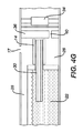
- the ENDS 4000 includes a housing 4016 containing a power source (not shown); a reusable mouthpiece 4024 including an electric heater 4014 , one or more air inlets 4017 , and an air outlet 4025 ; a vaporization chamber 4026 ; an elongate wick 4030 ; and a disposable cartridge 4020 containing a reservoir 4022 .
- the reusable mouthpiece 4024 is removably attachable to the housing 4016 to permit a disposable cartridge 4020 to be placed in the ENDS 4000 .
- the removable mouthpiece 4024 , the disposable cartridge 4020 and the base plate 4036 form the vaporization chamber 4026 in the assembled ENDS 4000 .
- ENDS 4000 will require an electrical circuit between the electric heater 4014 (contained in the mouthpiece 4024 ) and the power source (contained in the housing 4016 ). Therefore, a releasable electrical connection (not shown) is required between the housing 4016 and the mouthpiece 4024 .
- the electric heater 4014 is mounted on a base plate 4036 , and the electric heater 4014 is disposed in facing relation to the disposable cartridge 4020 , when assembled.
- the wick 4030 extends from the reservoir 4022 and into the electric heater 4014 .
- inlet air 4039 enters the ENDS 4000 through air inlets 4017 and enters the vaporization chamber 4026 perpendicular to the length of the heater where it forms the nicotine aerosol 4044 , as described above.
- the air/nicotine aerosol flow is perpendicular to the orientation of the electric heater 4014 .
- the nicotine aerosol 4044 can then be withdrawn from the air outlet 4025 in the reusable mouthpiece 4024 .
Landscapes
- Health & Medical Sciences (AREA)
- Engineering & Computer Science (AREA)
- Biomedical Technology (AREA)
- Animal Behavior & Ethology (AREA)
- Veterinary Medicine (AREA)
- Public Health (AREA)
- General Health & Medical Sciences (AREA)
- Anesthesiology (AREA)
- Life Sciences & Earth Sciences (AREA)
- Heart & Thoracic Surgery (AREA)
- Hematology (AREA)
- Pulmonology (AREA)
- Bioinformatics & Cheminformatics (AREA)
- Chemical & Material Sciences (AREA)
- General Chemical & Material Sciences (AREA)
- Chemical Kinetics & Catalysis (AREA)
- Catching Or Destruction (AREA)
- Manufacture Of Tobacco Products (AREA)
Priority Applications (1)
| Application Number | Priority Date | Filing Date | Title |
|---|---|---|---|
| US15/525,640 US10226076B2 (en) | 2014-11-17 | 2015-11-17 | Disposable cartridge for use in an electronic nicotine delivery system |
Applications Claiming Priority (3)
| Application Number | Priority Date | Filing Date | Title |
|---|---|---|---|
| US201462080666P | 2014-11-17 | 2014-11-17 | |
| US15/525,640 US10226076B2 (en) | 2014-11-17 | 2015-11-17 | Disposable cartridge for use in an electronic nicotine delivery system |
| PCT/EP2015/076879 WO2016079152A1 (en) | 2014-11-17 | 2015-11-17 | Disposable cartridge for use in an electronic nicotine delivery system |
Related Parent Applications (1)
| Application Number | Title | Priority Date | Filing Date |
|---|---|---|---|
| PCT/EP2015/076879 A-371-Of-International WO2016079152A1 (en) | 2014-11-17 | 2015-11-17 | Disposable cartridge for use in an electronic nicotine delivery system |
Related Child Applications (1)
| Application Number | Title | Priority Date | Filing Date |
|---|---|---|---|
| US16/257,215 Continuation US10531692B2 (en) | 2014-11-17 | 2019-01-25 | Disposable cartridge for use in an electronic nicotine delivery system |
Publications (2)
| Publication Number | Publication Date |
|---|---|
| US20170367407A1 US20170367407A1 (en) | 2017-12-28 |
| US10226076B2 true US10226076B2 (en) | 2019-03-12 |
Family
ID=54608512
Family Applications (3)
| Application Number | Title | Priority Date | Filing Date |
|---|---|---|---|
| US15/525,640 Expired - Fee Related US10226076B2 (en) | 2014-11-17 | 2015-11-17 | Disposable cartridge for use in an electronic nicotine delivery system |
| US16/257,215 Expired - Fee Related US10531692B2 (en) | 2014-11-17 | 2019-01-25 | Disposable cartridge for use in an electronic nicotine delivery system |
| US16/707,627 Active US10791768B2 (en) | 2014-11-17 | 2019-12-09 | Disposable cartridge for use in an electronic nicotine delivery system |
Family Applications After (2)
| Application Number | Title | Priority Date | Filing Date |
|---|---|---|---|
| US16/257,215 Expired - Fee Related US10531692B2 (en) | 2014-11-17 | 2019-01-25 | Disposable cartridge for use in an electronic nicotine delivery system |
| US16/707,627 Active US10791768B2 (en) | 2014-11-17 | 2019-12-09 | Disposable cartridge for use in an electronic nicotine delivery system |
Country Status (13)
| Country | Link |
|---|---|
| US (3) | US10226076B2 (zh) |
| EP (1) | EP3220759A1 (zh) |
| JP (1) | JP6710684B2 (zh) |
| KR (1) | KR20170083621A (zh) |
| CN (1) | CN106998813B (zh) |
| AU (1) | AU2015348439A1 (zh) |
| BR (1) | BR112017010106A2 (zh) |
| CA (1) | CA2967900A1 (zh) |
| IL (1) | IL251941B (zh) |
| MX (1) | MX2017006381A (zh) |
| RU (1) | RU2692831C2 (zh) |
| WO (1) | WO2016079152A1 (zh) |
| ZA (1) | ZA201704115B (zh) |
Cited By (10)
| Publication number | Priority date | Publication date | Assignee | Title |
|---|---|---|---|---|
| US20180223242A1 (en) * | 2017-02-06 | 2018-08-09 | Rosemount Inc. | Pressure transducer |
| US20180289058A1 (en) * | 2015-10-22 | 2018-10-11 | Shenzhen Smoore Technology Limited | Electronic Cigarette and Atomizer Thereof |
| US20190150514A1 (en) * | 2014-11-17 | 2019-05-23 | Mcneil Ab | Disposable cartridge for use in an electronic nicotine delivery system |
| US20200138108A1 (en) * | 2016-07-25 | 2020-05-07 | Altria Client Services Llc | Heater management |
| US10842199B2 (en) | 2014-11-17 | 2020-11-24 | Mcneil Ab | Electronic nicotine delivery system |
| US20210007414A1 (en) * | 2019-02-14 | 2021-01-14 | Glas, Inc. | Vaporization device having remotely controllable operational modes |
| US20210145053A1 (en) * | 2018-02-06 | 2021-05-20 | Mcneil Ab | Cartridge for electronic delivery system |
| WO2021191583A1 (en) * | 2020-03-26 | 2021-09-30 | Nicoventures Trading Limited | Cartridge for use with an aerosol provision system |
| US20210345670A1 (en) * | 2018-11-29 | 2021-11-11 | Shenzhen First Union Technology Co., Ltd. | Electronic cigarette atomizer and electronic cigarette comprising same |
| US11371902B2 (en) | 2019-12-27 | 2022-06-28 | Rosemount Inc. | Process venting feature for use in sensor applications with a process fluid barrier |
Families Citing this family (95)
| Publication number | Priority date | Publication date | Assignee | Title |
|---|---|---|---|---|
| US20160345631A1 (en) | 2005-07-19 | 2016-12-01 | James Monsees | Portable devices for generating an inhalable vapor |
| US11247003B2 (en) | 2010-08-23 | 2022-02-15 | Darren Rubin | Systems and methods of aerosol delivery with airflow regulation |
| US10279934B2 (en) | 2013-03-15 | 2019-05-07 | Juul Labs, Inc. | Fillable vaporizer cartridge and method of filling |
| US10159282B2 (en) | 2013-12-23 | 2018-12-25 | Juul Labs, Inc. | Cartridge for use with a vaporizer device |
| USD825102S1 (en) | 2016-07-28 | 2018-08-07 | Juul Labs, Inc. | Vaporizer device with cartridge |
| USD842536S1 (en) | 2016-07-28 | 2019-03-05 | Juul Labs, Inc. | Vaporizer cartridge |
| US10076139B2 (en) | 2013-12-23 | 2018-09-18 | Juul Labs, Inc. | Vaporizer apparatus |
| US20160366947A1 (en) | 2013-12-23 | 2016-12-22 | James Monsees | Vaporizer apparatus |
| FI3491948T4 (fi) | 2013-12-23 | 2024-05-06 | Juul Labs International Inc | Höyrystyslaitejärjestelmiä |
| US10058129B2 (en) | 2013-12-23 | 2018-08-28 | Juul Labs, Inc. | Vaporization device systems and methods |
| US9549573B2 (en) | 2013-12-23 | 2017-01-24 | Pax Labs, Inc. | Vaporization device systems and methods |
| US11478021B2 (en) | 2014-05-16 | 2022-10-25 | Juul Labs, Inc. | Systems and methods for aerosolizing a vaporizable material |
| EP3821735A1 (en) | 2014-12-05 | 2021-05-19 | Juul Labs, Inc. | Calibrated dose control |
| US10104913B2 (en) | 2015-04-22 | 2018-10-23 | Altria Client Services Llc | Pod assembly, dispensing body, and E-vapor apparatus including the same |
| USD980507S1 (en) | 2015-04-22 | 2023-03-07 | Altria Client Services Llc | Electronic vaping device |
| US10687554B2 (en) | 2015-04-22 | 2020-06-23 | Altria Client Services Llc | Connection device, cartridge and electronic vaping device |
| US10064432B2 (en) | 2015-04-22 | 2018-09-04 | Altria Client Services Llc | Pod assembly, dispensing body, and E-vapor apparatus including the same |
| USD874059S1 (en) | 2015-04-22 | 2020-01-28 | Altria Client Servies Llc | Electronic vaping device |
| US10251425B2 (en) * | 2015-07-06 | 2019-04-09 | Njoy, Llc | Vaporizing device with power component |
| EP3135134B1 (en) * | 2015-08-28 | 2018-06-13 | Fontem Holdings 2 B.V. | Electronic smoking device |
| CN205197001U (zh) * | 2015-11-25 | 2016-05-04 | 深圳市合元科技有限公司 | 分体式雾化器、电子烟及便于更换的储液装置 |
| CN114587024A (zh) | 2015-12-03 | 2022-06-07 | Jt国际股份公司 | 用于吸气装置的加热系统和加热方法 |
| EP3413960B1 (en) | 2016-02-11 | 2021-03-31 | Juul Labs, Inc. | Fillable vaporizer cartridge and method of filling |
| SG11201806801VA (en) | 2016-02-11 | 2018-09-27 | Juul Labs Inc | Securely attaching cartridges for vaporizer devices |
| US10405582B2 (en) | 2016-03-10 | 2019-09-10 | Pax Labs, Inc. | Vaporization device with lip sensing |
| US10264821B2 (en) * | 2016-03-21 | 2019-04-23 | Altria Client Services Llc | Electronic vaping device |
| CN105852225B (zh) * | 2016-06-16 | 2018-07-13 | 湖南中烟工业有限责任公司 | 一种抽屉式低温烟 |
| USD849996S1 (en) | 2016-06-16 | 2019-05-28 | Pax Labs, Inc. | Vaporizer cartridge |
| USD836541S1 (en) | 2016-06-23 | 2018-12-25 | Pax Labs, Inc. | Charging device |
| USD848057S1 (en) | 2016-06-23 | 2019-05-07 | Pax Labs, Inc. | Lid for a vaporizer |
| USD851830S1 (en) | 2016-06-23 | 2019-06-18 | Pax Labs, Inc. | Combined vaporizer tamp and pick tool |
| US10463077B2 (en) * | 2016-06-24 | 2019-11-05 | Altria Client Services Llc | Cartridge for e-vaping device with open-microchannels |
| GB201612231D0 (en) * | 2016-07-14 | 2016-08-31 | British American Tobacco Investments Ltd | Mouthpiece |
| US10278424B2 (en) * | 2016-07-21 | 2019-05-07 | Altria Client Services Llc | Electronic vaping device |
| US11660403B2 (en) | 2016-09-22 | 2023-05-30 | Juul Labs, Inc. | Leak-resistant vaporizer device |
| EP3554294B1 (en) * | 2016-12-19 | 2020-11-04 | Philip Morris Products S.a.s. | An aerosol-generating system comprising multiple aerosol-forming substrates and a piercing element |
| US11045615B2 (en) | 2016-12-19 | 2021-06-29 | Altria Client Services Llc | Vapor-generating systems |
| RU2747612C2 (ru) * | 2016-12-19 | 2021-05-11 | Филип Моррис Продактс С.А. | Система, генерирующая аэрозоль, содержащая несколько субстратов, образующих аэрозоль |
| JP7167028B2 (ja) | 2016-12-27 | 2022-11-08 | ジュール・ラブズ・インコーポレイテッド | 電子式ヴェポライザー用熱伝導芯 |
| US11696368B2 (en) | 2017-02-24 | 2023-07-04 | Altria Client Services Llc | Aerosol-generating system and a cartridge for an aerosol-generating system having a two-part liquid storage compartment |
| KR102602870B1 (ko) | 2017-02-24 | 2023-11-16 | 필립모리스 프로덕츠 에스.에이. | 에어로졸 발생 시스템 내 에어로졸 발생 요소를 위한 성형된 장착 |
| US11621570B2 (en) | 2017-04-18 | 2023-04-04 | Altria Client Services Llc | Aerosol-generating systems with overheating prevention |
| UA124646C2 (uk) * | 2017-04-18 | 2021-10-20 | Філіп Морріс Продактс С.А. | Система, що генерує аерозоль, із запобіганням перегріву |
| GB2561867B (en) * | 2017-04-25 | 2021-04-07 | Nerudia Ltd | Aerosol delivery system |
| WO2019046315A1 (en) | 2017-08-28 | 2019-03-07 | Juul Labs, Inc. | DRYER FOR SPRAY DEVICE |
| USD887632S1 (en) | 2017-09-14 | 2020-06-16 | Pax Labs, Inc. | Vaporizer cartridge |
| UA127587C2 (uk) * | 2017-09-18 | 2023-10-25 | Філіп Морріс Продактс С.А. | Картридж для генеруючої аерозоль системи |
| USD870375S1 (en) | 2017-10-11 | 2019-12-17 | Altria Client Services Llc | Battery for an electronic vaping device |
| US10772356B2 (en) | 2017-10-11 | 2020-09-15 | Altria Client Services Llc | Electronic vaping device including transfer pad with oriented fibers |
| GB201717480D0 (en) * | 2017-10-24 | 2017-12-06 | Nicoventures Holdings Ltd | Electronic aerosol provision device with seal |
| GB201717489D0 (en) | 2017-10-24 | 2017-12-06 | Nicoventures Holdings Ltd | Electronic aerosol provision device |
| GB201717486D0 (en) | 2017-10-24 | 2017-12-06 | Nicoventures Holdings Ltd | Mechanism for hatch of electronic aerosol provision device |
| GB201717484D0 (en) | 2017-10-24 | 2017-12-06 | Nicoventures Holdings Ltd | Electronic aerosol provision device |
| US10595523B2 (en) * | 2017-11-10 | 2020-03-24 | Techtoba Inc. | Forced air pesticide vaporizer with heatsink vaporization chamber and offset exhaust chamber |
| IL263217B (en) | 2017-11-24 | 2022-06-01 | Juul Labs Inc | Emission sensing and power circuit for vaporizers |
| GB201721766D0 (en) | 2017-12-22 | 2018-02-07 | British American Tobacco Investments Ltd | Electronic aerosol provision system |
| GB201721765D0 (en) | 2017-12-22 | 2018-02-07 | Nicoventures Holdings Ltd | Vapour provisions systems |
| US10687557B2 (en) | 2017-12-29 | 2020-06-23 | Altria Client Services Llc | Electronic vaping device with outlet-end illumination |
| KR102274250B1 (ko) * | 2018-04-09 | 2021-07-07 | 주식회사 아모센스 | 궐련형 전자담배장치용 발열히터 |
| US10986875B2 (en) | 2018-06-25 | 2021-04-27 | Juul Labs, Inc. | Vaporizer device heater control |
| WO2020002693A1 (en) | 2018-06-28 | 2020-01-02 | Philip Morris Products S.A. | Cartridge for an aerosol-generating system comprising an alkaloid source comprising a liquid alkaloid formulation |
| CA3107413A1 (en) | 2018-07-23 | 2020-01-30 | Juul Labs, Inc. | Airflow management for vaporizer device |
| WO2020025637A1 (en) * | 2018-08-01 | 2020-02-06 | Philip Morris Products S.A. | Extractor for an aerosol-generating device |
| US20210161209A1 (en) * | 2018-08-01 | 2021-06-03 | Philip Morris Products S.A. | Heater with at least two adjacent metal meshes |
| US11413409B2 (en) | 2018-09-12 | 2022-08-16 | Juul Labs, Inc. | Vaporizer including positive temperature coefficient of resistivity (PTCR) heating element |
| US20200113240A1 (en) * | 2018-10-12 | 2020-04-16 | Rai Strategic Holdings, Inc. | Vaporization system |
| GB2580213B (en) | 2018-10-15 | 2021-10-27 | Juul Labs Inc | Heating element |
| USD923865S1 (en) * | 2018-10-17 | 2021-06-29 | Shenzhen Smoore Technology Limited | Electronic cigarette |
| KR20210087962A (ko) | 2018-11-05 | 2021-07-13 | 쥴 랩스, 인크. | 기화기 디바이스용 카트리지 |
| WO2020132079A1 (en) * | 2018-12-21 | 2020-06-25 | Juul Labs Inc. | Vaporizer devices |
| EP3905906A1 (en) * | 2019-01-04 | 2021-11-10 | Juul Labs, Inc. | Vaporizer mouthpiece |
| US11553730B2 (en) * | 2019-02-01 | 2023-01-17 | Lunatech, Llc | Pre-filled vaporizing liquid container and personal vaporizing devices for using such container |
| US11253001B2 (en) | 2019-02-28 | 2022-02-22 | Juul Labs, Inc. | Vaporizer device with vaporizer cartridge |
| GB201903538D0 (en) * | 2019-03-15 | 2019-05-01 | Nicoventures Trading Ltd | Atomiser enclosure for a vapour provision system |
| EP3711609A1 (en) * | 2019-03-21 | 2020-09-23 | Nerudia Limited | Aerosol-generation apparatus and aerosol delivery system |
| US20220071285A1 (en) * | 2019-03-21 | 2022-03-10 | Nerudia Limited | Aerosol delivery system |
| EP3945907A1 (en) * | 2019-03-27 | 2022-02-09 | JT International SA | Electronic cigarette with wick |
| EP3741413A1 (en) * | 2019-05-24 | 2020-11-25 | Nerudia Limited | Refill device for aerosol delivery device |
| EP3753429A1 (en) * | 2019-06-21 | 2020-12-23 | Nerudia Limited | Aerosol delivery device |
| US11528937B2 (en) | 2019-11-26 | 2022-12-20 | Altria Client Services Llc | Nicotine pod assemblies and nicotine e-vaping devices |
| US11596172B2 (en) | 2019-11-26 | 2023-03-07 | Altria Client Services Llc | Non-nicotine pod assemblies and non-nicotine e-vaping devices |
| US11528939B2 (en) | 2019-11-26 | 2022-12-20 | Altria Client Services Llc | Non-nicotine pod assemblies and non-nicotine e-vaping devices |
| US11528938B2 (en) | 2019-11-26 | 2022-12-20 | Altria Client Services Llc | Non-nicotine pod assemblies and non-nicotine e-vaping devices |
| US11490656B2 (en) | 2019-11-26 | 2022-11-08 | Altria Client Services Llc | Nicotine pod assemblies and nicotine e-vaping devices |
| US11576432B2 (en) | 2019-11-26 | 2023-02-14 | Altria Client Services Llc | Nicotine pod assemblies and nicotine e-vaping devices |
| US11564416B2 (en) | 2019-11-26 | 2023-01-31 | Altria Client Services Llc | Non-nicotine pod assemblies and non-nicotine e-vaping devices |
| US11484062B2 (en) | 2019-11-26 | 2022-11-01 | Altria Client Services Llc | Nicotine pod assemblies and nicotine e-vaping devices |
| WO2022009364A1 (ja) * | 2020-07-09 | 2022-01-13 | 日本たばこ産業株式会社 | エアロゾル生成装置の本体ユニット、エアロゾル生成装置、及び、非燃焼式吸引器 |
| ES2965016T3 (es) * | 2020-08-25 | 2024-04-10 | Shenzhen Huachengda Prec Industry Co Ltd | Unidad de atomización con un paso tortuoso de aire y conjunto de atomización |
| KR102527343B1 (ko) | 2020-10-23 | 2023-05-02 | 주식회사 케이티앤지 | 액상 조성물을 포함하는 에어로졸 생성 물품 및 이를 포함하는 에어로졸 생성 시스템 |
| WO2022096580A1 (en) * | 2020-11-06 | 2022-05-12 | Jt International S.A. | Aerosol generation device |
| WO2023052070A1 (en) * | 2021-09-28 | 2023-04-06 | Jt International Sa | Consumable article for a vapour generating device |
| CA212420S (en) * | 2021-11-17 | 2023-11-17 | Shenzhen Verdewell Tech Limited | Electronic atomizing device |
| WO2023119665A1 (ja) * | 2021-12-24 | 2023-06-29 | 日本たばこ産業株式会社 | 非燃焼型香味吸引器の本体ユニット及び非燃焼型香味吸引器 |
| WO2023213952A1 (en) * | 2022-05-06 | 2023-11-09 | Philip Morris Products S.A. | A heater assembly for an aerosol generating system |
Citations (64)
| Publication number | Priority date | Publication date | Assignee | Title |
|---|---|---|---|---|
| US3520629A (en) | 1968-07-18 | 1970-07-14 | Teibow Co Ltd | Writing instruments |
| US4274479A (en) | 1978-09-21 | 1981-06-23 | Thermacore, Inc. | Sintered grooved wicks |
| EP0503767A1 (en) | 1991-03-11 | 1992-09-16 | Philip Morris Products Inc. | Flavor generating article |
| US5322075A (en) | 1992-09-10 | 1994-06-21 | Philip Morris Incorporated | Heater for an electric flavor-generating article |
| US5408574A (en) | 1989-12-01 | 1995-04-18 | Philip Morris Incorporated | Flat ceramic heater having discrete heating zones |
| US5498855A (en) | 1992-09-11 | 1996-03-12 | Philip Morris Incorporated | Electrically powered ceramic composite heater |
| WO1998016262A1 (en) | 1996-10-16 | 1998-04-23 | S.C. Johnson & Son, Inc. | Air freshener device with dispensing actuator feature |
| US5750964A (en) | 1991-03-11 | 1998-05-12 | Philip Morris Incorporated | Electrical heater of an electrical smoking system |
| US20030075188A1 (en) | 2001-10-24 | 2003-04-24 | Brown & Williamson Tobacco Corporation | Non-combustible smoking device and fuel element |
| JP2005106313A (ja) | 2003-09-29 | 2005-04-21 | Nec Toshiba Space Systems Ltd | ループヒートパイプ用蒸発器 |
| EP2113178A1 (en) | 2008-04-30 | 2009-11-04 | Philip Morris Products S.A. | An electrically heated smoking system having a liquid storage portion |
| GB2471453A (en) | 2009-06-29 | 2011-01-05 | Nigel Harold Morris | Fragrance Capsule |
| US20110048682A1 (en) | 2009-08-31 | 2011-03-03 | Fu Zhun Precision Industry (Shen Zhen) Co., Ltd. | Heat dissipation device |
| EP2340729A1 (en) | 2009-12-30 | 2011-07-06 | Philip Morris Products S.A. | An improved heater for an electrically heated aerosol generating system |
| WO2011146375A2 (en) | 2010-05-15 | 2011-11-24 | Noah Mark Minskoff | Personal vaporizing inhaler with safety wick |
| US20120006342A1 (en) | 2009-03-17 | 2012-01-12 | Philip Morris Products S.A. | Tobacco-based aerosol generation system |
| US8156944B2 (en) | 2006-05-16 | 2012-04-17 | Ruyan Investments (Holdings) Limited | Aerosol electronic cigarette |
| EP2460424A1 (en) | 2010-12-03 | 2012-06-06 | Philip Morris Products S.A. | An aerosol generating system with leakage prevention |
| US20120255567A1 (en) | 2009-09-16 | 2012-10-11 | Philip Morris Products S.A. | Improved device and method for delivery of a medicament |
| WO2013083634A1 (en) | 2011-12-08 | 2013-06-13 | Philip Morris Products S.A. | An aerosol generating device with a capillary interface |
| WO2013083638A1 (en) | 2011-12-08 | 2013-06-13 | Philip Morris Products S.A. | An aerosol generating device with air flow nozzles |
| WO2013083635A1 (en) | 2011-12-07 | 2013-06-13 | Philip Morris Products S.A. | An aerosol generating device having airflow inlets |
| EP2606756A1 (en) | 2009-10-27 | 2013-06-26 | Philip Morris Products S.A. | A smoking system having a liquid storage portion and improved airflow characteristics |
| US20130160764A1 (en) * | 2011-12-23 | 2013-06-27 | Qiuming Liu | Mouthpiece device of electronic cigarette |
| US20130192615A1 (en) | 2012-01-31 | 2013-08-01 | Altria Client Services Inc. | Electronic cigarette |
| KR101293857B1 (ko) | 2012-03-06 | 2013-08-07 | 박선순 | 관통로를 가진 도가니 포함한 전자담배 무화기 구조체 |
| KR101293859B1 (ko) | 2012-03-02 | 2013-08-07 | 박선순 | 액상 공급관 및 도가니를 포함한 전자 담배 무화기 구조체 |
| US20130340750A1 (en) | 2010-12-03 | 2013-12-26 | Philip Morris Products S.A. | Electrically Heated Aerosol Generating System Having Improved Heater Control |
| US20130340775A1 (en) | 2012-04-25 | 2013-12-26 | Bernard Juster | Application development for a network with an electronic cigarette |
| US20140014126A1 (en) | 2012-07-11 | 2014-01-16 | Eyal Peleg | Hot-wire control for an electronic cigarette |
| GB2504076A (en) | 2012-07-16 | 2014-01-22 | Nicoventures Holdings Ltd | Electronic smoking device |
| WO2014012894A1 (en) | 2012-07-16 | 2014-01-23 | Nicoventures Holding Limited | Electronic vapour provision device |
| US20140020693A1 (en) | 2010-12-24 | 2014-01-23 | Philip Morris Products S.A | Aerosol generating system having means for determining depletion of a liquid substrate |
| US20140109921A1 (en) | 2012-09-29 | 2014-04-24 | Shenzhen Smoore Technology Limited | Electronic cigarette |
| US20140130816A1 (en) | 2012-11-12 | 2014-05-15 | Qiuming Liu | Electornic cigarette device, electronic cigarette and atomizing device thereof |
| US20140144429A1 (en) | 2012-11-28 | 2014-05-29 | E-Nicotine Technology, Inc. | Methods and devices for compound delivery |
| US20140150784A1 (en) | 2012-12-05 | 2014-06-05 | Qiuming Liu | Smoke Condensation Resistant Electronic Cigarette |
| US20140190496A1 (en) | 2012-11-28 | 2014-07-10 | E-Nicotine Technology, Inc. | Methods and devices for compound delivery |
| US20140209105A1 (en) | 2013-01-30 | 2014-07-31 | R.J. Reynolds Tobacco Company | Wick suitable for use in an electronic smoking article |
| US20140238422A1 (en) | 2013-02-22 | 2014-08-28 | Altria Client Services Inc. | Electronic smoking article |
| CN203828069U (zh) | 2014-03-06 | 2014-09-17 | 刘秋明 | 一种电子烟 |
| CN203828073U (zh) | 2014-03-28 | 2014-09-17 | 刘秋明 | 一种电子烟及其烟油瓶 |
| CN203828084U (zh) | 2014-03-18 | 2014-09-17 | 刘秋明 | 一种电子烟 |
| WO2014139609A2 (en) | 2013-03-15 | 2014-09-18 | Philip Morris Products S.A. | An aerosol-generating system with a replacable mouthpiece cover |
| WO2014139610A1 (en) | 2013-03-15 | 2014-09-18 | Philip Morris Products S.A. | A method of manufacture for a heater assembly for use with a liquid filled cartridge |
| US20140283855A1 (en) | 2013-03-22 | 2014-09-25 | Altria Client Services Inc. | Electronic smoking article |
| US20140318558A1 (en) | 2012-12-27 | 2014-10-30 | Qiuming Liu | Electronic Cigarette and Its Nozzle |
| GB2513638A (en) | 2013-05-02 | 2014-11-05 | Nicoventures Holdings Ltd | Electronic cigarette |
| CN104126873A (zh) | 2014-07-07 | 2014-11-05 | 深圳市合元科技有限公司 | 用于电子烟的雾化头、雾化器及电子烟 |
| WO2014187770A2 (en) | 2013-05-21 | 2014-11-27 | Philip Morris Products S.A. | Electrically heated aerosol delivery system |
| US20150083147A1 (en) | 2013-09-26 | 2015-03-26 | Altria Client Services Inc. | Electronic smoking article |
| US20150090279A1 (en) * | 2013-09-29 | 2015-04-02 | Shenzhen Smoore Technology Limited | Electronic cigarette |
| US20150289567A1 (en) * | 2014-04-15 | 2015-10-15 | Kimree Hi-Tech Inc. | Electronic cigarette |
| US20160029698A1 (en) * | 2014-07-31 | 2016-02-04 | Huizhou Kimree Technology Co., Ltd | Electronic cigarette and information collection method |
| US20160120222A1 (en) * | 2013-06-03 | 2016-05-05 | Fontem Holdings 2 B.V. | System with electronic smoking device and capsule |
| US20160135505A1 (en) * | 2014-11-14 | 2016-05-19 | Shenzhen First Union Technology Co., Ltd. | Atomizing device and electronic cigarette having same |
| WO2016079155A1 (en) | 2014-11-17 | 2016-05-26 | Mcneil Ab | Electronic nicotine delivery system |
| WO2016079152A1 (en) | 2014-11-17 | 2016-05-26 | Mcneil Ab | Disposable cartridge for use in an electronic nicotine delivery system |
| WO2016079151A1 (en) | 2014-11-17 | 2016-05-26 | Mcneil Ab | Child-resistant container for nicotine-containing cartridges |
| US20160143365A1 (en) * | 2012-04-01 | 2016-05-26 | Kimree Hi-Tech Inc. | Electronic cigarette and mouthpiece part thereof |
| US20160183596A1 (en) * | 2014-12-30 | 2016-06-30 | Lubby Holdings, LLC | Personal vaporizer |
| US20170119055A1 (en) * | 2014-04-02 | 2017-05-04 | Kimree Hi-Tech Inc. | Atomization assembly and electronic cigarette |
| US20170231286A1 (en) * | 2014-10-17 | 2017-08-17 | Fontem Holdings 1 B.V. | Capsule having a liquid transporting element for uses with an electronic smoking device |
| US20170367402A1 (en) * | 2016-06-24 | 2017-12-28 | Raymond Lau | Cartridge for e-vaping device with open-microchannels |
Family Cites Families (13)
| Publication number | Priority date | Publication date | Assignee | Title |
|---|---|---|---|---|
| GB9600562D0 (en) | 1996-01-11 | 1996-03-13 | Delta Theta Ltd | Domestic kettle |
| FR2901955B1 (fr) | 2006-06-05 | 2010-03-26 | Seb Sa | Appareil menager pour le chauffage de liquide |
| CN201238609Y (zh) * | 2008-07-21 | 2009-05-20 | 北京格林世界科技发展有限公司 | 电子烟用电子雾化器 |
| GB0823491D0 (en) | 2008-12-23 | 2009-01-28 | Kind Consumer Ltd | A simulated cigarette device |
| US20100181387A1 (en) | 2009-12-01 | 2010-07-22 | Zaffaroni Alejandro C | Aerosol delivery system and uses thereof |
| CN104839892B (zh) * | 2010-04-30 | 2020-01-21 | 富特姆 4 有限公司 | 电子吸烟设备 |
| RU103281U1 (ru) * | 2010-12-27 | 2011-04-10 | Общество с ограниченной ответственностью "ПромКапитал" | Электронная сигарета |
| US9351522B2 (en) * | 2011-09-29 | 2016-05-31 | Robert Safari | Cartomizer e-cigarette |
| ES2661023T3 (es) | 2011-12-08 | 2018-03-27 | Philip Morris Products S.A. | Dispositivo generador de aerosol con flujo de aire ajustable |
| AU2012360817B2 (en) * | 2011-12-30 | 2017-09-07 | Philip Morris Products S.A. | Aerosol generating device with improved temperature distribution |
| US9820509B2 (en) * | 2013-10-10 | 2017-11-21 | Kyle D. Newton | Electronic cigarette with encoded cartridge |
| WO2015063126A1 (en) * | 2013-10-29 | 2015-05-07 | Choukroun Benjamin | Smoking cessation device |
| CN203709256U (zh) * | 2014-01-13 | 2014-07-16 | 潘凡 | 一次性电子香烟 |
-
2015
- 2015-11-17 BR BR112017010106-8A patent/BR112017010106A2/pt active Search and Examination
- 2015-11-17 EP EP15797645.7A patent/EP3220759A1/en not_active Withdrawn
- 2015-11-17 CN CN201580062347.1A patent/CN106998813B/zh not_active Expired - Fee Related
- 2015-11-17 CA CA2967900A patent/CA2967900A1/en not_active Abandoned
- 2015-11-17 MX MX2017006381A patent/MX2017006381A/es unknown
- 2015-11-17 KR KR1020177016406A patent/KR20170083621A/ko unknown
- 2015-11-17 JP JP2017526528A patent/JP6710684B2/ja not_active Expired - Fee Related
- 2015-11-17 US US15/525,640 patent/US10226076B2/en not_active Expired - Fee Related
- 2015-11-17 WO PCT/EP2015/076879 patent/WO2016079152A1/en active Application Filing
- 2015-11-17 RU RU2017121110A patent/RU2692831C2/ru active
- 2015-11-17 AU AU2015348439A patent/AU2015348439A1/en not_active Abandoned
-
2017
- 2017-04-26 IL IL251941A patent/IL251941B/en active IP Right Grant
- 2017-06-15 ZA ZA2017/04115A patent/ZA201704115B/en unknown
-
2019
- 2019-01-25 US US16/257,215 patent/US10531692B2/en not_active Expired - Fee Related
- 2019-12-09 US US16/707,627 patent/US10791768B2/en active Active
Patent Citations (68)
| Publication number | Priority date | Publication date | Assignee | Title |
|---|---|---|---|---|
| US3520629A (en) | 1968-07-18 | 1970-07-14 | Teibow Co Ltd | Writing instruments |
| US4274479A (en) | 1978-09-21 | 1981-06-23 | Thermacore, Inc. | Sintered grooved wicks |
| US5408574A (en) | 1989-12-01 | 1995-04-18 | Philip Morris Incorporated | Flat ceramic heater having discrete heating zones |
| US5750964A (en) | 1991-03-11 | 1998-05-12 | Philip Morris Incorporated | Electrical heater of an electrical smoking system |
| EP0503767A1 (en) | 1991-03-11 | 1992-09-16 | Philip Morris Products Inc. | Flavor generating article |
| US5322075A (en) | 1992-09-10 | 1994-06-21 | Philip Morris Incorporated | Heater for an electric flavor-generating article |
| US5498855A (en) | 1992-09-11 | 1996-03-12 | Philip Morris Incorporated | Electrically powered ceramic composite heater |
| WO1998016262A1 (en) | 1996-10-16 | 1998-04-23 | S.C. Johnson & Son, Inc. | Air freshener device with dispensing actuator feature |
| US20030075188A1 (en) | 2001-10-24 | 2003-04-24 | Brown & Williamson Tobacco Corporation | Non-combustible smoking device and fuel element |
| JP2005106313A (ja) | 2003-09-29 | 2005-04-21 | Nec Toshiba Space Systems Ltd | ループヒートパイプ用蒸発器 |
| US8156944B2 (en) | 2006-05-16 | 2012-04-17 | Ruyan Investments (Holdings) Limited | Aerosol electronic cigarette |
| EP2113178A1 (en) | 2008-04-30 | 2009-11-04 | Philip Morris Products S.A. | An electrically heated smoking system having a liquid storage portion |
| US20120006342A1 (en) | 2009-03-17 | 2012-01-12 | Philip Morris Products S.A. | Tobacco-based aerosol generation system |
| GB2471453A (en) | 2009-06-29 | 2011-01-05 | Nigel Harold Morris | Fragrance Capsule |
| US20110048682A1 (en) | 2009-08-31 | 2011-03-03 | Fu Zhun Precision Industry (Shen Zhen) Co., Ltd. | Heat dissipation device |
| US20120255567A1 (en) | 2009-09-16 | 2012-10-11 | Philip Morris Products S.A. | Improved device and method for delivery of a medicament |
| EP2606756A1 (en) | 2009-10-27 | 2013-06-26 | Philip Morris Products S.A. | A smoking system having a liquid storage portion and improved airflow characteristics |
| US20150264979A1 (en) | 2009-12-30 | 2015-09-24 | Philip Morris Usa Inc. | Heater for an electrically heated aerosol generating system |
| EP2340729A1 (en) | 2009-12-30 | 2011-07-06 | Philip Morris Products S.A. | An improved heater for an electrically heated aerosol generating system |
| WO2011146375A2 (en) | 2010-05-15 | 2011-11-24 | Noah Mark Minskoff | Personal vaporizing inhaler with safety wick |
| EP2460424A1 (en) | 2010-12-03 | 2012-06-06 | Philip Morris Products S.A. | An aerosol generating system with leakage prevention |
| US20130340750A1 (en) | 2010-12-03 | 2013-12-26 | Philip Morris Products S.A. | Electrically Heated Aerosol Generating System Having Improved Heater Control |
| US20140020693A1 (en) | 2010-12-24 | 2014-01-23 | Philip Morris Products S.A | Aerosol generating system having means for determining depletion of a liquid substrate |
| WO2013083635A1 (en) | 2011-12-07 | 2013-06-13 | Philip Morris Products S.A. | An aerosol generating device having airflow inlets |
| US20140346689A1 (en) * | 2011-12-08 | 2014-11-27 | Philip Morris Products S.A. | Aerosol generating device with a capillary interface |
| WO2013083634A1 (en) | 2011-12-08 | 2013-06-13 | Philip Morris Products S.A. | An aerosol generating device with a capillary interface |
| WO2013083638A1 (en) | 2011-12-08 | 2013-06-13 | Philip Morris Products S.A. | An aerosol generating device with air flow nozzles |
| US20130160764A1 (en) * | 2011-12-23 | 2013-06-27 | Qiuming Liu | Mouthpiece device of electronic cigarette |
| US20130192615A1 (en) | 2012-01-31 | 2013-08-01 | Altria Client Services Inc. | Electronic cigarette |
| KR101293859B1 (ko) | 2012-03-02 | 2013-08-07 | 박선순 | 액상 공급관 및 도가니를 포함한 전자 담배 무화기 구조체 |
| KR101293857B1 (ko) | 2012-03-06 | 2013-08-07 | 박선순 | 관통로를 가진 도가니 포함한 전자담배 무화기 구조체 |
| US20160143365A1 (en) * | 2012-04-01 | 2016-05-26 | Kimree Hi-Tech Inc. | Electronic cigarette and mouthpiece part thereof |
| US20130340775A1 (en) | 2012-04-25 | 2013-12-26 | Bernard Juster | Application development for a network with an electronic cigarette |
| US20140014126A1 (en) | 2012-07-11 | 2014-01-16 | Eyal Peleg | Hot-wire control for an electronic cigarette |
| GB2504076A (en) | 2012-07-16 | 2014-01-22 | Nicoventures Holdings Ltd | Electronic smoking device |
| WO2014012894A1 (en) | 2012-07-16 | 2014-01-23 | Nicoventures Holding Limited | Electronic vapour provision device |
| US20140109921A1 (en) | 2012-09-29 | 2014-04-24 | Shenzhen Smoore Technology Limited | Electronic cigarette |
| US20140130816A1 (en) | 2012-11-12 | 2014-05-15 | Qiuming Liu | Electornic cigarette device, electronic cigarette and atomizing device thereof |
| US20140144429A1 (en) | 2012-11-28 | 2014-05-29 | E-Nicotine Technology, Inc. | Methods and devices for compound delivery |
| US20140190496A1 (en) | 2012-11-28 | 2014-07-10 | E-Nicotine Technology, Inc. | Methods and devices for compound delivery |
| US20140150784A1 (en) | 2012-12-05 | 2014-06-05 | Qiuming Liu | Smoke Condensation Resistant Electronic Cigarette |
| US20140318558A1 (en) | 2012-12-27 | 2014-10-30 | Qiuming Liu | Electronic Cigarette and Its Nozzle |
| US20140209105A1 (en) | 2013-01-30 | 2014-07-31 | R.J. Reynolds Tobacco Company | Wick suitable for use in an electronic smoking article |
| US20140238422A1 (en) | 2013-02-22 | 2014-08-28 | Altria Client Services Inc. | Electronic smoking article |
| WO2014139609A2 (en) | 2013-03-15 | 2014-09-18 | Philip Morris Products S.A. | An aerosol-generating system with a replacable mouthpiece cover |
| WO2014139610A1 (en) | 2013-03-15 | 2014-09-18 | Philip Morris Products S.A. | A method of manufacture for a heater assembly for use with a liquid filled cartridge |
| US20140283855A1 (en) | 2013-03-22 | 2014-09-25 | Altria Client Services Inc. | Electronic smoking article |
| GB2513638A (en) | 2013-05-02 | 2014-11-05 | Nicoventures Holdings Ltd | Electronic cigarette |
| WO2014187770A2 (en) | 2013-05-21 | 2014-11-27 | Philip Morris Products S.A. | Electrically heated aerosol delivery system |
| US20160120222A1 (en) * | 2013-06-03 | 2016-05-05 | Fontem Holdings 2 B.V. | System with electronic smoking device and capsule |
| US20150083147A1 (en) | 2013-09-26 | 2015-03-26 | Altria Client Services Inc. | Electronic smoking article |
| US20150090279A1 (en) * | 2013-09-29 | 2015-04-02 | Shenzhen Smoore Technology Limited | Electronic cigarette |
| CN203828069U (zh) | 2014-03-06 | 2014-09-17 | 刘秋明 | 一种电子烟 |
| CN203828084U (zh) | 2014-03-18 | 2014-09-17 | 刘秋明 | 一种电子烟 |
| CN203828073U (zh) | 2014-03-28 | 2014-09-17 | 刘秋明 | 一种电子烟及其烟油瓶 |
| US20170119055A1 (en) * | 2014-04-02 | 2017-05-04 | Kimree Hi-Tech Inc. | Atomization assembly and electronic cigarette |
| US20150289567A1 (en) * | 2014-04-15 | 2015-10-15 | Kimree Hi-Tech Inc. | Electronic cigarette |
| US20160000147A1 (en) | 2014-07-07 | 2016-01-07 | Shenzhen First Union Technology Co., Ltd. | Atomizing head, atomizer and electronic cigarette having same |
| CN104126873A (zh) | 2014-07-07 | 2014-11-05 | 深圳市合元科技有限公司 | 用于电子烟的雾化头、雾化器及电子烟 |
| US20160029698A1 (en) * | 2014-07-31 | 2016-02-04 | Huizhou Kimree Technology Co., Ltd | Electronic cigarette and information collection method |
| US20170231286A1 (en) * | 2014-10-17 | 2017-08-17 | Fontem Holdings 1 B.V. | Capsule having a liquid transporting element for uses with an electronic smoking device |
| US20160135505A1 (en) * | 2014-11-14 | 2016-05-19 | Shenzhen First Union Technology Co., Ltd. | Atomizing device and electronic cigarette having same |
| WO2016079152A1 (en) | 2014-11-17 | 2016-05-26 | Mcneil Ab | Disposable cartridge for use in an electronic nicotine delivery system |
| WO2016079151A1 (en) | 2014-11-17 | 2016-05-26 | Mcneil Ab | Child-resistant container for nicotine-containing cartridges |
| WO2016079155A1 (en) | 2014-11-17 | 2016-05-26 | Mcneil Ab | Electronic nicotine delivery system |
| US20170360092A1 (en) * | 2014-11-17 | 2017-12-21 | Mcneil Ab | Electronic nicotine delivery system |
| US20160183596A1 (en) * | 2014-12-30 | 2016-06-30 | Lubby Holdings, LLC | Personal vaporizer |
| US20170367402A1 (en) * | 2016-06-24 | 2017-12-28 | Raymond Lau | Cartridge for e-vaping device with open-microchannels |
Non-Patent Citations (9)
| Title |
|---|
| Adkison et al., "Electronic Nicotine Delivery Systems: International Tobacco Control Four-Country Survey," American Journal of Preventive Medicine, vol. 44, Issue 3, pp. 207-215 (Mar. 2013). |
| International search report and Written Opinion dated Feb. 29, 2016, for PCT/EP2015/076879. |
| International search report and Written Opinion dated May 4, 2016, for PCT/EP2015/076883. |
| PCT/EP2015/076878 filed Nov. 17, 2015, published WO 2016/079151. |
| PCT/EP2015/076879 filed Nov. 17, 2015, published WO 2016/079152. |
| PCT/EP2015/076883 filed Nov. 17, 2015, published WO 2016/079155. |
| U.S. Appl. No. 62/080,656, filed Nov. 17, 2014. |
| U.S. Appl. No. 62/080,661, filed Nov. 17, 2014. |
| U.S. Appl. No. 62/080,666, filed Nov. 17, 2014. |
Cited By (23)
| Publication number | Priority date | Publication date | Assignee | Title |
|---|---|---|---|---|
| US10842199B2 (en) | 2014-11-17 | 2020-11-24 | Mcneil Ab | Electronic nicotine delivery system |
| US20190150514A1 (en) * | 2014-11-17 | 2019-05-23 | Mcneil Ab | Disposable cartridge for use in an electronic nicotine delivery system |
| US10531692B2 (en) * | 2014-11-17 | 2020-01-14 | Mcneil Ab | Disposable cartridge for use in an electronic nicotine delivery system |
| US10791768B2 (en) * | 2014-11-17 | 2020-10-06 | Mcneil Ab | Disposable cartridge for use in an electronic nicotine delivery system |
| US20180289058A1 (en) * | 2015-10-22 | 2018-10-11 | Shenzhen Smoore Technology Limited | Electronic Cigarette and Atomizer Thereof |
| US11412581B2 (en) | 2015-10-22 | 2022-08-09 | Shenzhen Smoore Technology Limited | Electronic cigarette and atomizing assembly and atomizing element thereof |
| US10993475B2 (en) * | 2015-10-22 | 2021-05-04 | Shenzhen Smoore Technology Limited | Electronic cigarette and atomizer thereof |
| US20200138108A1 (en) * | 2016-07-25 | 2020-05-07 | Altria Client Services Llc | Heater management |
| US10905169B2 (en) * | 2016-07-25 | 2021-02-02 | Altria Client Services Llc | Heater management |
| US11950327B2 (en) | 2016-07-25 | 2024-04-02 | Altria Client Services Llc | Heater management based on heater resistance |
| US10584309B2 (en) * | 2017-02-06 | 2020-03-10 | Rosemount Inc. | Pressure transducer for single-use containers |
| US20180223242A1 (en) * | 2017-02-06 | 2018-08-09 | Rosemount Inc. | Pressure transducer |
| US20210145053A1 (en) * | 2018-02-06 | 2021-05-20 | Mcneil Ab | Cartridge for electronic delivery system |
| US11930843B2 (en) * | 2018-02-06 | 2024-03-19 | Mcneil Ab | Cartridge for electronic delivery system |
| US20210345670A1 (en) * | 2018-11-29 | 2021-11-11 | Shenzhen First Union Technology Co., Ltd. | Electronic cigarette atomizer and electronic cigarette comprising same |
| US20210378301A1 (en) * | 2019-02-14 | 2021-12-09 | Glas, Inc. | Vaporization device having remotely controllable operational modes |
| US20210007414A1 (en) * | 2019-02-14 | 2021-01-14 | Glas, Inc. | Vaporization device having remotely controllable operational modes |
| US11903415B2 (en) * | 2019-02-14 | 2024-02-20 | Glas, Inc. | Vaporization device having remotely controllable operational modes |
| US11903416B2 (en) * | 2019-02-14 | 2024-02-20 | Glas, Inc. | Vaporization device having remotely controllable operational modes |
| US11910827B2 (en) * | 2019-02-14 | 2024-02-27 | Glas, Inc. | Vaporization device having remotely controllable operational modes |
| US20210127751A1 (en) * | 2019-02-14 | 2021-05-06 | Glas, Inc. | Vaporization device having remotely controllable operational modes |
| US11371902B2 (en) | 2019-12-27 | 2022-06-28 | Rosemount Inc. | Process venting feature for use in sensor applications with a process fluid barrier |
| WO2021191583A1 (en) * | 2020-03-26 | 2021-09-30 | Nicoventures Trading Limited | Cartridge for use with an aerosol provision system |
Also Published As
| Publication number | Publication date |
|---|---|
| US10791768B2 (en) | 2020-10-06 |
| US20190150514A1 (en) | 2019-05-23 |
| JP2017533726A (ja) | 2017-11-16 |
| US10531692B2 (en) | 2020-01-14 |
| ZA201704115B (en) | 2019-01-30 |
| IL251941B (en) | 2020-10-29 |
| BR112017010106A2 (pt) | 2018-01-02 |
| RU2017121110A3 (zh) | 2019-04-23 |
| EP3220759A1 (en) | 2017-09-27 |
| US20200107586A1 (en) | 2020-04-09 |
| IL251941A0 (en) | 2017-06-29 |
| AU2015348439A1 (en) | 2017-05-18 |
| WO2016079152A1 (en) | 2016-05-26 |
| RU2017121110A (ru) | 2018-12-19 |
| JP6710684B2 (ja) | 2020-06-17 |
| CN106998813B (zh) | 2020-05-01 |
| CN106998813A (zh) | 2017-08-01 |
| CA2967900A1 (en) | 2016-05-26 |
| KR20170083621A (ko) | 2017-07-18 |
| RU2692831C2 (ru) | 2019-06-28 |
| US20170367407A1 (en) | 2017-12-28 |
| MX2017006381A (es) | 2017-08-21 |
Similar Documents
| Publication | Publication Date | Title |
|---|---|---|
| US10791768B2 (en) | Disposable cartridge for use in an electronic nicotine delivery system | |
| US10842199B2 (en) | Electronic nicotine delivery system | |
| WO2016079151A1 (en) | Child-resistant container for nicotine-containing cartridges | |
| RU2730164C2 (ru) | Генерирующее аэрозоль устройство, имеющее боковую полость | |
| RU2760356C2 (ru) | Генерирующая аэрозоль система, которая содержит картридж, содержащий гель, и устройство для нагревания катриджа | |
| RU2717637C2 (ru) | Картриджный узел для образующей аэрозоль системы и образующая аэрозоль система, содержащая картриджный узел | |
| EP3462933B1 (en) | Heat diffuser for an aerosol-generating system | |
| CA3021541A1 (en) | Aerosol generating device with multiple heaters | |
| IL262319A (en) | An item for creating a spray with a heat spreader | |
| CA3017429A1 (en) | Aerosol generating device with piercing assembly | |
| IL262307B (en) | Heat spreader for a system to create a spray | |
| EP3890528B1 (en) | Aerosol-generating system | |
| RU2793873C2 (ru) | Картридж для системы, генерирующей аэрозоль, содержащий источник алкалоида, содержащий жидкий состав на основе алкалоида |
Legal Events
| Date | Code | Title | Description |
|---|---|---|---|
| AS | Assignment |
Owner name: KINNEIR DUFORT DESIGN LIMITED, GREAT BRITAIN Free format text: ASSIGNMENT OF ASSIGNORS INTEREST;ASSIGNORS:ALTHORPE, CHRISTOPHER;BINDER, IAN JAMES;MCLEOD, DAVID ANDREW;REEL/FRAME:043640/0097 Effective date: 20170713 Owner name: MCNEIL AB, SWEDEN Free format text: ASSIGNMENT OF ASSIGNORS INTEREST;ASSIGNOR:KINNEIR DUFORT DESIGN LIMITED;REEL/FRAME:043640/0249 Effective date: 20170726 Owner name: MCNEIL AB, SWEDEN Free format text: ASSIGNMENT OF ASSIGNORS INTEREST;ASSIGNORS:KELEPOURIS, LEE;MUHAMMED, SALIH MUHSIN;NORDSTROM, JOHAN;AND OTHERS;SIGNING DATES FROM 20170705 TO 20170914;REEL/FRAME:043640/0022 |
|
| STCF | Information on status: patent grant |
Free format text: PATENTED CASE |
|
| FEPP | Fee payment procedure |
Free format text: MAINTENANCE FEE REMINDER MAILED (ORIGINAL EVENT CODE: REM.); ENTITY STATUS OF PATENT OWNER: LARGE ENTITY |
|
| LAPS | Lapse for failure to pay maintenance fees |
Free format text: PATENT EXPIRED FOR FAILURE TO PAY MAINTENANCE FEES (ORIGINAL EVENT CODE: EXP.); ENTITY STATUS OF PATENT OWNER: LARGE ENTITY |
|
| STCH | Information on status: patent discontinuation |
Free format text: PATENT EXPIRED DUE TO NONPAYMENT OF MAINTENANCE FEES UNDER 37 CFR 1.362 |
|
| FP | Lapsed due to failure to pay maintenance fee |
Effective date: 20230312 |