US10220395B2 - Water stop device and shower head - Google Patents
Water stop device and shower head Download PDFInfo
- Publication number
- US10220395B2 US10220395B2 US15/379,095 US201615379095A US10220395B2 US 10220395 B2 US10220395 B2 US 10220395B2 US 201615379095 A US201615379095 A US 201615379095A US 10220395 B2 US10220395 B2 US 10220395B2
- Authority
- US
- United States
- Prior art keywords
- sealing
- passage
- sealing ring
- sealing element
- water stop
- Prior art date
- Legal status (The legal status is an assumption and is not a legal conclusion. Google has not performed a legal analysis and makes no representation as to the accuracy of the status listed.)
- Active, expires
Links
Images


Classifications
-
- B—PERFORMING OPERATIONS; TRANSPORTING
- B05—SPRAYING OR ATOMISING IN GENERAL; APPLYING FLUENT MATERIALS TO SURFACES, IN GENERAL
- B05B—SPRAYING APPARATUS; ATOMISING APPARATUS; NOZZLES
- B05B1/00—Nozzles, spray heads or other outlets, with or without auxiliary devices such as valves, heating means
- B05B1/30—Nozzles, spray heads or other outlets, with or without auxiliary devices such as valves, heating means designed to control volume of flow, e.g. with adjustable passages
- B05B1/3026—Nozzles, spray heads or other outlets, with or without auxiliary devices such as valves, heating means designed to control volume of flow, e.g. with adjustable passages the controlling element being a gate valve, a sliding valve or a cock
-
- B—PERFORMING OPERATIONS; TRANSPORTING
- B05—SPRAYING OR ATOMISING IN GENERAL; APPLYING FLUENT MATERIALS TO SURFACES, IN GENERAL
- B05B—SPRAYING APPARATUS; ATOMISING APPARATUS; NOZZLES
- B05B1/00—Nozzles, spray heads or other outlets, with or without auxiliary devices such as valves, heating means
- B05B1/30—Nozzles, spray heads or other outlets, with or without auxiliary devices such as valves, heating means designed to control volume of flow, e.g. with adjustable passages
-
- B—PERFORMING OPERATIONS; TRANSPORTING
- B05—SPRAYING OR ATOMISING IN GENERAL; APPLYING FLUENT MATERIALS TO SURFACES, IN GENERAL
- B05B—SPRAYING APPARATUS; ATOMISING APPARATUS; NOZZLES
- B05B12/00—Arrangements for controlling delivery; Arrangements for controlling the spray area
- B05B12/002—Manually-actuated controlling means, e.g. push buttons, levers or triggers
-
- B—PERFORMING OPERATIONS; TRANSPORTING
- B05—SPRAYING OR ATOMISING IN GENERAL; APPLYING FLUENT MATERIALS TO SURFACES, IN GENERAL
- B05B—SPRAYING APPARATUS; ATOMISING APPARATUS; NOZZLES
- B05B1/00—Nozzles, spray heads or other outlets, with or without auxiliary devices such as valves, heating means
- B05B1/14—Nozzles, spray heads or other outlets, with or without auxiliary devices such as valves, heating means with multiple outlet openings; with strainers in or outside the outlet opening
- B05B1/18—Roses; Shower heads
-
- Y—GENERAL TAGGING OF NEW TECHNOLOGICAL DEVELOPMENTS; GENERAL TAGGING OF CROSS-SECTIONAL TECHNOLOGIES SPANNING OVER SEVERAL SECTIONS OF THE IPC; TECHNICAL SUBJECTS COVERED BY FORMER USPC CROSS-REFERENCE ART COLLECTIONS [XRACs] AND DIGESTS
- Y02—TECHNOLOGIES OR APPLICATIONS FOR MITIGATION OR ADAPTATION AGAINST CLIMATE CHANGE
- Y02A—TECHNOLOGIES FOR ADAPTATION TO CLIMATE CHANGE
- Y02A20/00—Water conservation; Efficient water supply; Efficient water use
- Y02A20/40—Protecting water resources
Definitions
- the present invention relates to a water stop device.
- a shower head needs to turn off temporally when the user wants to apply shower gel or shampoo.
- Traditional shower head can only switch to open or close the water by the outlet switch, which is inconvenient.
- the main technical solution of the present invention is to provide with a water stop device, which can occupy small space such to decrease the diameter of the inlet pipe efficiently.
- a water stop device comprising: a main body, a transmitting element and a sealing element;
- the main body is disposed with an inlet passage, a diversion passage and a confluence passage in the axial direction in order; the diversion passage is connected to the confluence passage by a normal-open hole;
- one end of the sealing element is coupled to the transmitting element in transmitting way, such that the sealing element moves between a first position and a second position along the axial direction of the confluence passage; the diversion passage is connected to the confluence passage when the sealing element is situated in the first position; the sealing element closes the confluence passage when the sealing element is situated in the second position.
- the main body is disposed with a chamber in the inlet passage, one end of the chamber is an opening end configured to be faced to confluence passage along the axial direction of the main body; water flows out of the inlet passage and impacts the bottom end of the external wall of the chamber then divides to the diversion passage at the side of the chamber.
- the external periphery of the sealing element is disposed with a first sealing ring, when the sealing element switches between the first position and the second position in the axial direction of the confluence passage, the first sealing element always contacts with the side wall of the chamber in sealing way.
- the external periphery of one end of the sealing element is disposed with a second sealing ring coaxial to the first sealing ring, the first sealing ring and the second sealing ring are equal in size; when the sealing element is situated in the second position, the second sealing ring contacts with the side wall of the confluence passage in sealing way; when the sealing element is situated in the first position, the second sealing ring separates from the side wall of the confluence passage.
- the transmitting element is a push rod disposed in the axial direction of the main body, the end of the push rod is connected to the sealing element; the external periphery of one end of the sealing element connected to the push rod is further disposed with a third sealing ring coaxial to the first sealing ring, the first sealing ring and the third sealing ring are equal in size; the third sealing ring always contacts with the side wall of the confluence passage in sealing way.
- the side wall of the confluence passage is disposed with an outlet, the outlet is disposed between the second sealing ring and the third sealing ring.
- the front end of the push rod is disposed with a lock ring, the lock ring is linked to an activating element, when the activating element is operated, the push rod drives the sealing element to move in the axial direction of the main body.
- the activating element is a push button or a rocker switch.
- the chamber is disposed with an air exhausting hole to connect the chamber and the outside air.
- the present invention is further provided with a shower head, which is assembled with the water stop device above mentioned.
- the present invention is provided with a water stop device that the sealing element and the chamber are disposed in the axial direction of the main body, so that the water divides and converges in the axial direction; the sealing element moves in the axial direction of the main body to open and close the confluence passage to realize the switch of water stop and water supplying; as the motions of the sealing element are in the axial direction, it requires lower to the pipe diameter of the inlet pipe, the diameter of the inlet pipe needn't to increase due to the water stop device.
- the first sealing ring is coaxial to the third sealing ring, and they are equal in size, when the confluence passage is open, the first sealing ring and the third sealing ring are subjected to water pressure force in the confluence passage at the same time.
- Two acting forces are equal in power and opposite in direction, such that they exactly neutralize each other. Therefore, water pressure doesn't influence the sealing element during the switching from water supplying state to water stop state.
- FIG. 1 illustrates a schematic diagram of a water stop device of Embodiment 1 of the present invention in water supplying state.
- FIG. 2 illustrates a schematic diagram of the water stop device of Embodiment of the present invention in water stop state.
- FIG. 3 illustrates a sectional diagram of a shower head of Embodiment 1 of the present invention in water supplying state.
- FIG. 4 illustrates a sectional diagram of the shower head of Embodiment 1 of the present invention in water stop state.
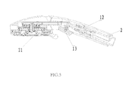
- FIG. 5 illustrates a sectional diagram of a shower head of Embodiment 2 of the present invention in water supplying state.
- FIG. 6 illustrates a sectional diagram of the shower head of Embodiment 2 of the present invention in water stop state.
- this embodiment is provided with a shower head, which comprises a shower head main body 1 and a water stop device 2 .
- the shower head main body 1 comprises an outlet cover plate 11 and an inlet pipe 12 ; the water stop device 2 is disposed in the inlet pipe 12 .
- the water stop device 2 comprises a main body 21 , a transmitting element 22 and a sealing element 23 .
- the main body 21 is disposed with an inlet passage 211 , a confluence passage 213 and a chamber 214 in the axial direction in order; one end of the chamber 214 is an opening end; the opening end is configured to be faced to confluence passage 213 along the axial direction of the main body 21 ; water flows out of the inlet passage 211 and impacts the bottom end of the external wall of the chamber 214 then divides to two sides of the external wall of the chamber 214 , therefore, a diversion passage 212 is formed at two sides of the chamber 214 .
- the inlet passage 211 , the diversion passage 212 , the confluence passage 213 are arranged in the axial direction of the main body 21 , and the diversion passage 212 is connected to the confluence passage 213 by a normal-open hole 215 .
- One end of the sealing element 23 is coupled to the transmitting element 22 in transmitting way, such that the sealing element 23 moves between a first position and a second position along the axial direction of the confluence passage 213 ; the external periphery of the sealing element 23 is disposed with a first sealing ring 231 , when the sealing element 23 switches between the first position and the second position in the axial direction of the confluence passage 213 , the first sealing element 231 always contacts with the side wall of the chamber 214 in sealing way.
- the chamber 214 is disposed with an air exhausting hole 216 to connect the chamber 214 and the outside air.
- the external periphery of the sealing element 23 is disposed with a second sealing ring 232 coaxial to the first sealing ring 231 , the first sealing ring 231 and the second sealing ring 232 are equal in size; when the sealing element 23 is situated in the second position, the second sealing ring 232 contacts with the side wall of the confluence passage 213 in sealing way; when the sealing element 23 is situated in the first position, the second sealing ring 232 separates from the side wall of the confluence passage 213 . Therefore, water stop function and water supplying function are switched.
- this embodiment requires lower to the pipe diameter of the inlet pipe 12 , the diameter of the inlet pipe 12 needn't to increase due to the water stop device 2 .
- the transmitting element 22 is a push rod disposed in the axial direction of the main body 21 , the end of the push rod is connected to the sealing element 23 ; the external periphery of one end of the sealing element 23 connected to the push rod is further disposed with a third sealing ring 233 coaxial to the first sealing ring 231 , the first sealing ring 231 and the third sealing ring 233 are equal in size; the third sealing ring 233 always contacts with the side wall of the confluence passage 213 in sealing way.
- the side wall of the confluence passage 231 is disposed with an outlet 217 , which is disposed between the second sealing ring 232 and the third sealing ring 233 .
- the first sealing ring 231 is coaxial to the third sealing ring 233 , and they are equal in size, when the confluence passage 213 is open, the first sealing ring 231 and the third sealing ring 233 are subjected to water pressure force in the confluence passage 213 at the same time.
- Two acting forces are equal in power and opposite in direction, such that they exactly neutralize each other. Therefore, water pressure doesn't influence the sealing element during the switching from water supplying state to water stop state.
- the sealing element 23 moves to the right along the chamber 214 ; air in the chamber 214 exhausts out through the air exhaust hole 216 , preventing switching failure due to increased air pressure when the chamber 214 is compressed.
- the needed switch force is very small to switch the water stop device 2 , and the switch hand feeling is well.
- the front end of the push rod is disposed with a lock ring 221 , which is linked to an activating element 13 , in this embodiment, the activating element 13 is a push button disposed at the front end of the inlet pipe 12 , the push button is locked to the lock ring 221 , therefore, when the push button is pushed, it drives the push rod to move in the axial direction of the main body 21 so as to drive the sealing element 23 to move in the same direction.
- the activating element 13 is a push button disposed at the front end of the inlet pipe 12 , the push button is locked to the lock ring 221 , therefore, when the push button is pushed, it drives the push rod to move in the axial direction of the main body 21 so as to drive the sealing element 23 to move in the same direction.
- this embodiment differs from Embodiment 1 from that: the activating element 13 is a rocker switch, the other portion of this embodiment is similar to Embodiment 1.
Landscapes
- Bathtubs, Showers, And Their Attachments (AREA)
- Nozzles (AREA)
- Domestic Plumbing Installations (AREA)
Applications Claiming Priority (3)
| Application Number | Priority Date | Filing Date | Title |
|---|---|---|---|
| CN201610685981 | 2016-08-18 | ||
| CN201610685981.7A CN107755111B (zh) | 2016-08-18 | 2016-08-18 | 止水装置和花洒 |
| CN201610685981.7 | 2016-08-18 |
Publications (2)
| Publication Number | Publication Date |
|---|---|
| US20180050353A1 US20180050353A1 (en) | 2018-02-22 |
| US10220395B2 true US10220395B2 (en) | 2019-03-05 |
Family
ID=61191061
Family Applications (1)
| Application Number | Title | Priority Date | Filing Date |
|---|---|---|---|
| US15/379,095 Active 2037-05-02 US10220395B2 (en) | 2016-08-18 | 2016-12-14 | Water stop device and shower head |
Country Status (2)
| Country | Link |
|---|---|
| US (1) | US10220395B2 (zh) |
| CN (1) | CN107755111B (zh) |
Cited By (1)
| Publication number | Priority date | Publication date | Assignee | Title |
|---|---|---|---|---|
| US20190277413A1 (en) * | 2018-03-09 | 2019-09-12 | Runner (Xiamen) Corp. | Push button switching spool |
Families Citing this family (1)
| Publication number | Priority date | Publication date | Assignee | Title |
|---|---|---|---|---|
| CN112292212B (zh) * | 2018-06-29 | 2022-11-15 | 洁碧有限公司 | 用于喷淋头的暂停组件 |
Citations (10)
| Publication number | Priority date | Publication date | Assignee | Title |
|---|---|---|---|---|
| US20040112985A1 (en) * | 2002-11-08 | 2004-06-17 | Malek Michael L. | Pullout spray head with single-button mode selector |
| US20080067264A1 (en) * | 2006-09-19 | 2008-03-20 | Erickson Perry D | Faucet Spray Control Assembly |
| US8152078B2 (en) * | 2006-10-25 | 2012-04-10 | Masco Corporation Of Indiana | Faucet spray head |
| EP2561930A1 (en) * | 2011-08-23 | 2013-02-27 | H.D. Hudson Manufacturing Company | Springless shut-off valve for liquid sprayers |
| US8424781B2 (en) * | 2006-02-06 | 2013-04-23 | Masco Corporation Of Indiana | Power sprayer |
| US20130161549A1 (en) * | 2010-09-29 | 2013-06-27 | Xiamen Solex High-Tech Industries Co., Ltd. | Flow adjusting device with a button |
| US20140076993A1 (en) * | 2011-05-10 | 2014-03-20 | Xiamen Solex High-Tech Industries Co., Ltd. | High temperature protective valve and the use thereof in a shower head |
| US8727241B2 (en) * | 2010-05-05 | 2014-05-20 | Amfag S.P.A. | Kitchen sink sprayer |
| US20160305099A1 (en) * | 2015-04-18 | 2016-10-20 | Xiamen Runner Industrial Corporation | Temporary stop water output device |
| US9708800B2 (en) * | 2010-12-15 | 2017-07-18 | Orlando Bosio | Kitchen sink sprayer |
Family Cites Families (7)
| Publication number | Priority date | Publication date | Assignee | Title |
|---|---|---|---|---|
| CN201727426U (zh) * | 2010-07-12 | 2011-02-02 | 厦门市易洁卫浴有限公司 | 一种带插座的出水机构 |
| CN102818081B (zh) * | 2011-12-31 | 2015-12-16 | 凯迈(洛阳)气源有限公司 | 导气环 |
| JP5141998B1 (ja) * | 2012-03-16 | 2013-02-13 | Toto株式会社 | ハンドシャワーヘッド |
| CN103498980B (zh) * | 2013-08-30 | 2015-06-24 | 北京航天发射技术研究所 | 一种连接接头 |
| CN204122270U (zh) * | 2014-08-21 | 2015-01-28 | 路达(厦门)工业有限公司 | 一种储水泼水花洒 |
| CN104500822B (zh) * | 2014-12-26 | 2018-05-01 | 四川欧迅能源工程科技有限公司 | 一种具有阀芯受力平衡的高压电动截止阀 |
| CN206168600U (zh) * | 2016-08-18 | 2017-05-17 | 厦门松霖科技有限公司 | 一种止水装置和花洒 |
-
2016
- 2016-08-18 CN CN201610685981.7A patent/CN107755111B/zh active Active
- 2016-12-14 US US15/379,095 patent/US10220395B2/en active Active
Patent Citations (13)
| Publication number | Priority date | Publication date | Assignee | Title |
|---|---|---|---|---|
| US20040112985A1 (en) * | 2002-11-08 | 2004-06-17 | Malek Michael L. | Pullout spray head with single-button mode selector |
| US8424781B2 (en) * | 2006-02-06 | 2013-04-23 | Masco Corporation Of Indiana | Power sprayer |
| US20080067264A1 (en) * | 2006-09-19 | 2008-03-20 | Erickson Perry D | Faucet Spray Control Assembly |
| US8152078B2 (en) * | 2006-10-25 | 2012-04-10 | Masco Corporation Of Indiana | Faucet spray head |
| US8727241B2 (en) * | 2010-05-05 | 2014-05-20 | Amfag S.P.A. | Kitchen sink sprayer |
| US20130161549A1 (en) * | 2010-09-29 | 2013-06-27 | Xiamen Solex High-Tech Industries Co., Ltd. | Flow adjusting device with a button |
| US9470334B2 (en) * | 2010-09-29 | 2016-10-18 | Xiamen Solex High-Tech Industries Co., Ltd. | Flow adjusting device with a button |
| US9708800B2 (en) * | 2010-12-15 | 2017-07-18 | Orlando Bosio | Kitchen sink sprayer |
| US20140076993A1 (en) * | 2011-05-10 | 2014-03-20 | Xiamen Solex High-Tech Industries Co., Ltd. | High temperature protective valve and the use thereof in a shower head |
| US9770726B2 (en) * | 2011-05-10 | 2017-09-26 | Xiamen Solex High-Tech Industries Co., Ltd. | High temperature protective valve and the use thereof in a shower head |
| EP2561930A1 (en) * | 2011-08-23 | 2013-02-27 | H.D. Hudson Manufacturing Company | Springless shut-off valve for liquid sprayers |
| US20160305099A1 (en) * | 2015-04-18 | 2016-10-20 | Xiamen Runner Industrial Corporation | Temporary stop water output device |
| US9828750B2 (en) * | 2015-04-18 | 2017-11-28 | Xiamen Runner Industrial Corporation | Temporary stop water output device |
Cited By (1)
| Publication number | Priority date | Publication date | Assignee | Title |
|---|---|---|---|---|
| US20190277413A1 (en) * | 2018-03-09 | 2019-09-12 | Runner (Xiamen) Corp. | Push button switching spool |
Also Published As
| Publication number | Publication date |
|---|---|
| CN107755111B (zh) | 2023-07-07 |
| US20180050353A1 (en) | 2018-02-22 |
| CN107755111A (zh) | 2018-03-06 |
Similar Documents
| Publication | Publication Date | Title |
|---|---|---|
| US9615697B2 (en) | Combined pilot valve mechanism and a shower system applied with the combined pilot valve mechanism | |
| US10391504B2 (en) | Water stop switch device and shower head | |
| US20150090812A1 (en) | Pilot valve switch mechanism and a combined shower applied with the pilot valve switch mechanism | |
| CN107350097B (zh) | 一种带止水功能和水路切换功能的花洒 | |
| US20180104707A1 (en) | Combined Shower | |
| US20150115064A1 (en) | Shower system combining a top sprayer and a hand shower | |
| US20160221006A1 (en) | Multifunctional shower head | |
| US10675643B2 (en) | Water discharge structure having reset function and a pull-out head having a water discharge structure | |
| US9470334B2 (en) | Flow adjusting device with a button | |
| US20150090813A1 (en) | Pilot valve switch mechanism and a shower system applied with the pilot valve switch mechanism | |
| US9573143B2 (en) | Side spraying shower head | |
| US10220395B2 (en) | Water stop device and shower head | |
| CN205371703U (zh) | 一种按压切换出水装置 | |
| WO2019128224A1 (zh) | 喷枪及具有其的洗车机 | |
| WO2018120279A1 (zh) | 一种按钮切换出水功能的手持花洒 | |
| US20210197216A1 (en) | Shower device | |
| CN210196557U (zh) | 一种多功能抽拉花洒 | |
| US20160074883A1 (en) | Handle rotating switch shower head | |
| US20210197215A1 (en) | Waterway switching valve | |
| US20210108398A1 (en) | Water outlet device with water stop and flow rate control | |
| CN110159808B (zh) | 一种多功能抽拉花洒 | |
| CN204590205U (zh) | 一种具有自洁功能的洁身器 | |
| US20070236007A1 (en) | Modified water separator | |
| US10788144B1 (en) | Flow switch operated by single button | |
| WO2016050063A1 (zh) | 饮水机及其水龙头 |
Legal Events
| Date | Code | Title | Description |
|---|---|---|---|
| AS | Assignment |
Owner name: XIAMEN SOLEX HIGH-TECH INDUSTRIES CO., LTD., CHINA Free format text: ASSIGNMENT OF ASSIGNORS INTEREST;ASSIGNORS:LIN, FENGDE;GONG, HAILANG;ZHANG, MINGFU;AND OTHERS;REEL/FRAME:040737/0058 Effective date: 20161213 |
|
| STCF | Information on status: patent grant |
Free format text: PATENTED CASE |
|
| MAFP | Maintenance fee payment |
Free format text: PAYMENT OF MAINTENANCE FEE, 4TH YEAR, LARGE ENTITY (ORIGINAL EVENT CODE: M1551); ENTITY STATUS OF PATENT OWNER: LARGE ENTITY Year of fee payment: 4 |