US10192384B2 - Money item handling device and conveyor - Google Patents

Money item handling device and conveyor Download PDF

Info

Publication number
US10192384B2
US10192384B2 US15/326,645 US201515326645A US10192384B2 US 10192384 B2 US10192384 B2 US 10192384B2 US 201515326645 A US201515326645 A US 201515326645A US 10192384 B2 US10192384 B2 US 10192384B2
Authority
US
United States
Prior art keywords
capture
money item
conveyor
money
lugs
Prior art date
Legal status (The legal status is an assumption and is not a legal conclusion. Google has not performed a legal analysis and makes no representation as to the accuracy of the status listed.)
Active
Application number
US15/326,645
Other versions
US20170206729A1 (en
Inventor
Robert James Blythin
Andrew Barson
David Taylor
Current Assignee (The listed assignees may be inaccurate. Google has not performed a legal analysis and makes no representation or warranty as to the accuracy of the list.)
Crane Payment Innovations Ltd
Original Assignee
Crane Payment Innovations Ltd
Priority date (The priority date is an assumption and is not a legal conclusion. Google has not performed a legal analysis and makes no representation as to the accuracy of the date listed.)
Filing date
Publication date
Application filed by Crane Payment Innovations Ltd filed Critical Crane Payment Innovations Ltd
Publication of US20170206729A1 publication Critical patent/US20170206729A1/en
Assigned to CRANE PAYMENT INNOVATIONS LIMITED reassignment CRANE PAYMENT INNOVATIONS LIMITED ASSIGNMENT OF ASSIGNORS INTEREST (SEE DOCUMENT FOR DETAILS). Assignors: BARSON, Andrew, TAYLOR, DAVID, BLYTHIN, Robert James
Assigned to CRANE PAYMENT INNOVATIONS LIMITED reassignment CRANE PAYMENT INNOVATIONS LIMITED CHANGE OF NAME (SEE DOCUMENT FOR DETAILS). Assignors: CRANE PAYMENT SOLUTIONS LIMITED
Application granted granted Critical
Publication of US10192384B2 publication Critical patent/US10192384B2/en
Active legal-status Critical Current
Anticipated expiration legal-status Critical

Links

Images

Classifications

    • GPHYSICS
    • G07CHECKING-DEVICES
    • G07DHANDLING OF COINS OR VALUABLE PAPERS, e.g. TESTING, SORTING BY DENOMINATIONS, COUNTING, DISPENSING, CHANGING OR DEPOSITING
    • G07D9/00Counting coins; Handling of coins not provided for in the other groups of this subclass
    • G07D9/008Feeding coins from bulk
    • GPHYSICS
    • G07CHECKING-DEVICES
    • G07DHANDLING OF COINS OR VALUABLE PAPERS, e.g. TESTING, SORTING BY DENOMINATIONS, COUNTING, DISPENSING, CHANGING OR DEPOSITING
    • G07D1/00Coin dispensers
    • GPHYSICS
    • G07CHECKING-DEVICES
    • G07DHANDLING OF COINS OR VALUABLE PAPERS, e.g. TESTING, SORTING BY DENOMINATIONS, COUNTING, DISPENSING, CHANGING OR DEPOSITING
    • G07D9/00Counting coins; Handling of coins not provided for in the other groups of this subclass
    • G07D9/04Hand- or motor-driven devices for counting coins

Definitions

  • This specification relates to a money item handling device and particularly to a conveyor to receive and convey money items having a generally discoidal surface, such as coins and tokens.
  • Money item handling devices are commercially available that employ a conveyor to transport coins and like money items to a processing station, for example for validation and temporary storage prior to being paid out to a user, for example as change in a vending machine transaction.
  • a handling device comprises a receiving station for receiving money items having a generally discoidal surface and a peripheral edge supplied thereto, a money item processing station, and a conveyor configured to convey money items from the money item receiving station to the processing station, the conveyor comprising a conveyor member having a money item receiving surface, and first and second lugs upstanding from said surface each having forward facing capture regions configured to be driven in a longitudinal conveying direction through the money item receiving station to receive a money item with its major discoidal surface overlying the surface and with its peripheral edge abutting the capture regions of the lugs, one of the capture regions of the lugs being upstanding from said money item receiving surface at least in part by a height greater than the other capture region.
  • the capture regions may be so arranged that if first and second of said money items become lodged on the money item receiving surface and abutting the first and second capture regions respectively, upon forward movement of the conveyor in the longitudinal conveying direction, the first money item is urged by the first capture region against the second money item so as to dislodge the second money item from abutment with the second capture region so that solely the first money item is held in abutment with the first and second capture regions.
  • the receiving station may be configured to receive a plurality of money items of different dimensions that comprise opposed, spaced apart, generally discoidal major surfaces with a thickness dimension between the major surfaces falling within a predetermined thickness range having a minimum thickness value, wherein the maximum height by which the capture regions of first and second lugs are each upstanding from the money item receiving surface is more than said minimum thickness value and less than said minimum thickness value respectively.
  • the lugs may be disposed on opposite sides of a longitudinal axis of the conveyor member, and the capture region of the first lug may comprise a capture surface facing forwardly in the longitudinal conveying direction, having a height which reduces in the direction of said longitudinal axis, and may be trapezoidal, forming an acute angle with the longitudinal axis in the conveying direction and with a height that increases outwardly from the longitudinal axis.
  • the second capture region may comprise an upstanding capture edge at the join of first and second guide surfaces that are upstanding from the money item receiving surface and diverge rearwardly with respect to said longitudinal conveying direction.
  • At least one scoop surface on the or each of the first and second lugs may be provided, so that if first and second of the money items become arranged in a stack in engagement with the capture region of the first lug, an upper one of the money items is guided by the or each said scoop surface to pass by the lugs upon forward movement of the conveyor in said longitudinal conveying direction such that solely the lowermost money item in the stack abuts the first and second capture regions.
  • the scoop surfaces may diverge from the money item receiving surface rearwardly of said longitudinal conveying direction.
  • the height of the second capture region may be less than 1.2 mm for example 1.0 mm or less, and the height of the first capture region is at least in part greater than that of the first capture region.
  • a plurality of said conveyor members may pivotally connected and provided with a respective set of said first and second lugs, and the conveyor may be configured in a continuous loop comprising an elevating section extending from the money item receiving section to the processing section, and a descending section extending back to the receiving section, the first and second capture regions being configured to hold a single one of the money items during passage of the conveyor along the elevating section.
  • the first and second lugs may include respective support surfaces facing rearwardly in said conveying direction for supporting a money item that remains on the conveyor after passage through the processing station during conveyance along the descending section.
  • a toothed track may be recessed in the or each said conveyor member, and a motor driven gear may be provided to engage with the track to drive the conveyor.
  • a conveyor to receive and convey money items having a generally discoidal surface and a peripheral edge comprising a conveyor member having a money item receiving surface, and first and second lugs upstanding from said surface each having forward facing capture regions configured to be driven in a longitudinal conveying direction through a money item receiving station to receive a money item with its major discoidal surface overlying the surface and with its peripheral edge abutting the capture regions of the lugs, one of the capture regions of the lugs being upstanding from said money item receiving surface at least in part by a height greater than the other capture region, and the capture regions are so arranged that if first and second of said money items become lodged on the money item receiving surface and abutting the first and second capture regions respectively, upon forward movement of the conveyor in the longitudinal conveying direction, the first money item is urged by the first capture region against the second money item so as to dislodge the second money item from abutment with the second capture region so that solely the first money item is held in abutment with the
  • the term “money item” includes coins which are issued by or on behalf of Governmental organisations that have generally disc shaped major surfaces, including coins in the US$ coin set, Euro coin set, GB pound coin set and the like.
  • the coins may be circular or other discoidal shapes such as the hexagonal shape of a GB 50 pence piece and may include holes such as a central hole found in some coins.
  • the term includes other disc shaped items with an attributable monetary value, such as tokens used in casinos.
  • FIG. 1 is schematic diagram illustrating features of a money handling device
  • FIG. 2 is a perspective view from above of links of a conveyor for use in the money handling device of FIG. 1 ;
  • FIG. 3 is a perspective view from below of the links of the conveyor shown FIG. 2 ;
  • FIG. 4 is a schematic illustration of how coins of different diameters and thicknesses can be received on the conveyor
  • FIG. 5 illustrates how a stack of coins received on the conveyor are singulated i.e. separated so that only one coin is received and conveyed by the link;
  • FIG. 6 is a perspective view of the singulation process shown in FIG. 5 ;
  • FIG. 7 illustrates a singulation process for two coins side by side on the conveyor
  • FIG. 8 shows capture of a coin on a downward descent of the conveyor.
  • a money item handling device which in this example is operable to store and pay out coins of different denominations e.g. to provide change for a monetary transaction.
  • the device comprises a housing 1 which receives coins 2 of predetermined different denominations through an inlet 3 , for example from coin acceptor devices which validate coins presented by a user during a vending transaction.
  • a continuous loop conveyor 4 is driven by a motor 5 to transport the coins 2 through the device for processing at one or more processing stations.
  • the coins 2 are received on the conveyor at a receiving station 6 and tend to adopt a non-uniform, random stacked configuration at various angles in the station 6 where they fall onto the conveyor 4 .
  • the conveyor is configured to transport the coins one by one i.e. in a singulated fashion along an elevating section 7 of the conveyor to a generally horizontal bridging section 8 which includes a processing station that includes coin sensor 9 and payout gates 10 .
  • Some coins may remain on the conveyor 4 after the payout gates 10 which pass along a descending section ii back to the receiving section 6 .
  • the coin sensor 9 may be an inductive sensor including coils (not shown) and/or optical sensors on one or both sides of the conveyor 4 to detect inductive and/or optical characteristics of the coin, which may be compared by a processor 14 with reference values held in a memory 15 to determine their authenticity and denomination.
  • the payout gates 10 may comprise solenoid operated gates controlled by the processor 14 , which can be selectively lowered so that selected coins moving along the surface 13 that have been detected by the sensor 9 to be of a particular denomination can be discharged into one or more outlet chutes 16 to be returned to the user, for example as change for the transaction.
  • the conveyor 4 is made up of links illustrated in more detail in FIGS. 2 and 3 , and comprises an alternating pattern of first and second link members 17 , 18 that are pivotly connected to one another by grips 19 that engage shafts 20 .
  • the link members 17 , 18 each include a generally planar money item receiving surface 21 which, in this example, receives coins, with the major discoidal surface of the coin 2 overlying the surface 21 , as illustrated schematically in FIG. 4 , with two coins of different diameters 2 ′′ and 2 ′′′ having respective major discoidal surfaces 22 , 22 ′ bounded by respective peripheries 23 , 23 ′.
  • the link members 17 , 18 have a longitudinal central axis L-L′ and the conveyor is configured to move in a longitudinal conveyance direction C as shown in FIG. 2 , along which the longitudinal axes of the link members 17 , 18 are arranged.
  • the link members 17 , 18 are formed with a recessed driveable element, such as an integrally moulded toothed track 24 which, as shown in FIG. 1 engages with gear 25 driven by motor 5 so as to move the conveyor in the longitudinal conveying direction C.
  • the toothed track is recessed into the link members 17 , 18 .
  • each of the link members has protruding guide stubs 27 that extend transversely to the longitudinal conveying direction C to be received in a guide slot (not shown) extending around the path of the looped conveyor to guide the links around the path.
  • the links 17 , 18 may include one or more recessed position locating elements for determining the position of the links 17 , 18 with respect to a path of the track.
  • the position locating elements mark the positions of each link 17 , 18 and may comprise a recessed optical element, such as a light guide or light reflector.
  • the position locating elements are discussed in the context of reflective panels 28 which are recessed into the body of the links 17 , 18 and may be detected by an optical detector 29 illustrated in FIG. 1 , so as to count the link members 17 as they are conveyed around the conveyor loop.
  • the first link members 17 include first and second lugs 30 , 31 which are upstanding from the money item receiving surface 21 and are disposed on opposite sides of the longitudinal axis L-L′.
  • the first and second lugs 30 , 31 are configured to guide coins from the non-uniform stack that occurs in the receiving section 6 shown in FIG. 1 into the location on the conveyor 4 shown in FIG. 4 , with a single coin captured between the lugs 30 , 31 , overlying the money item receiving surface 21 .
  • the first lug 30 has a forward facing capture region 33 in the form of trapezoidal surface which forms an angle ⁇ with longitudinal axis L-L′ in the conveying direction C, with a height that increases outwardly from the longitudinal axis.
  • the surface 33 forms a capture edge 34 with the main body of the lug 30 of a height h 1 which is not more than the minimum thickness of the various, predetermined acceptable denominations of coins that enter the receiving section 6 of FIG. 1 .
  • the height of the capture edge 34 may be less than 1.2 mm, typically 1.0 mm.
  • the maximum height h 2 of the trapezoidal surface 33 is typical three or four times greater than the minimum height h 1 so as to engage with coins in the non-uniform stack of the receiving section 6 and encourage one of them to lie flat on the money item receiving section 21 between the lugs 30 , 31 as the conveyor 4 passes through the receiving section 6 in the longitudinal conveying direction C.
  • the second lug 31 has a coin capture region in the form of an upstanding coin edge 35 at the join of first and second guide surfaces 36 , 37 that are upstanding from the money item receiving surface 21 and diverge rearwardly with respect to the longitudinal conveying direction C.
  • the capture edge 35 of lug 31 is of a height edge h 3 which is less than the minimum thickness of the coins 2 received in the receiving section 6 and may for example be equal to the height h 1 of the first lug 30 .
  • the height of the capture edge 35 may be less than 1.2 mm, typically 1.0 mm.
  • the coin capture regions 33 , 35 co-operate to capture a single coin from the non-uniform stack of coins in the receiving section 6 such that the captured coin becomes located between the capture edges 34 , 35 , overlying the money item receiving surface 21 .
  • the lugs 30 , 31 are configured to capture only one coin 2 from the stack as will now be explained with reference to FIGS. 5 and 6 .
  • the lugs 30 , 31 include scoop surfaces comprising a generally triangular, chined surface 38 on the first lug 30 together with a chined, scoop surface 38 ′ on the second lug 31 , so that, as shown in FIG.
  • the first and second lugs 30 , 31 are also configured to prevent two smaller coins becoming lodged side by side on the money item receiving surface 21 as the link members 17 , 18 pass through the coin receiving section 6 .
  • two coins 2 a , 2 b have become lodged against the first and second lugs 30 , 31 during the coin capture process in the coin receiving section 6 .
  • the coin 2 a it has been captured against the upstanding surface 34 , which is inclined at angle ⁇ to the longitudinal axis L-L′ as shown in FIG. 4 , so that as the conveyor moves forward in direction C, the coin 2 A shown in FIG.
  • the surface 36 of the second lug 31 is inclined at angle ⁇ to the longitudinal axis L-L′ so that, as shown in FIG. 7B , the coin 2 B then moves along the surface 36 in the direction of arrow Z and the coin 2 A then moves into a position captured between the capture edges 34 , 35 of the first and second lugs 30 , 31 .
  • each second link member 18 includes an upstanding lug 39 which is located to prevent two large coins such as two of the coin denomination 2 ′′′ shown in FIG. 4 becoming jammed between the successive pairs of lugs 30 , 31 shown in FIG. 4 .
  • the first and second lugs 30 , 31 also include inwardly inclined, upstanding support surfaces 40 , 41 that are facing rearwardly of the longitudinal conveying direction C, on opposite sides of the longinitudianl axis L-L′ so that when a coin captured between the capture edges 34 , 35 of first and second lugs 30 , 31 , after being slid over the horizontal surface of the bridging region 13 and entering the descending section 11 , the coin 2 C falls and slides over the surface 21 to abut the inclined surfaces 40 , 41 , so as to be retained on the conveyor during its descend through the descending section ii shown in FIG. 1 .
  • the coin handling device may be used not only for vending but also in casinos and other situations where coins or money item items such as tokens need to be processed.
  • the disclosure of the present application should be understood to include any novel features or any novel combination of features either explicitly or implicitly disclosed herein or in any generalisation thereof and during prosecution of the present application or of any application derived therefrom, new claims may be formulated to cover any such features and/or combination of such features. Many other variations will be evident to those skilled in the art falling within the scope of the claims hereinafter.

Landscapes

  • Physics & Mathematics (AREA)
  • General Physics & Mathematics (AREA)
  • Attitude Control For Articles On Conveyors (AREA)
  • Control Of Vending Devices And Auxiliary Devices For Vending Devices (AREA)

Abstract

A handling device for money items such as coins and tokens has a receiving station (6) at which coins are fed onto a conveyor (4) that feeds them one by one to a processing station (9). The conveyor is made up of conveyor link members (17, 18) having a money item receiving surface (21), and first and second lugs (30, 31) upstanding from the surface (21), each having forward facing capture regions (33, 35) configured to be driven in a longitudinal conveying direction C through the receiving station (6) to receive a coin or token its major discoidal surface overlying the surface (21) and with its peripheral edge abutting the capture regions (33,35) of the lugs (30,31), one of the capture regions of the lugs being upstanding from the surface (21) at least in part by a height (h2) greater than the other capture region (h3), so as to capture and singulate the coins in a manner that prevents two coins from being held, such that one of them is ejected.

Description

CROSS-REFERENCE TO RELATED APPLICATION(S)
The present application claims priority under 35 U.S.C. § 365 to International Patent Application No. PCT/GB2015/051886 filed Jun. 29, 2015, entitled “MONEY ITEM HANDLING DEVICE AND CONVEYOR”, and through International Patent Application No. PCT/GB2015/051886, to British Patent Application No. 1412633.8, filed Jul. 16, 2014, each of which are incorporated herein by reference into the present disclosure as if fully set forth herein.
FIELD
This specification relates to a money item handling device and particularly to a conveyor to receive and convey money items having a generally discoidal surface, such as coins and tokens.
BACKGROUND
Money item handling devices are commercially available that employ a conveyor to transport coins and like money items to a processing station, for example for validation and temporary storage prior to being paid out to a user, for example as change in a vending machine transaction.
SUMMARY
One embodiment of a handling device, comprises a receiving station for receiving money items having a generally discoidal surface and a peripheral edge supplied thereto, a money item processing station, and a conveyor configured to convey money items from the money item receiving station to the processing station, the conveyor comprising a conveyor member having a money item receiving surface, and first and second lugs upstanding from said surface each having forward facing capture regions configured to be driven in a longitudinal conveying direction through the money item receiving station to receive a money item with its major discoidal surface overlying the surface and with its peripheral edge abutting the capture regions of the lugs, one of the capture regions of the lugs being upstanding from said money item receiving surface at least in part by a height greater than the other capture region. The capture regions may be so arranged that if first and second of said money items become lodged on the money item receiving surface and abutting the first and second capture regions respectively, upon forward movement of the conveyor in the longitudinal conveying direction, the first money item is urged by the first capture region against the second money item so as to dislodge the second money item from abutment with the second capture region so that solely the first money item is held in abutment with the first and second capture regions.
The receiving station may be configured to receive a plurality of money items of different dimensions that comprise opposed, spaced apart, generally discoidal major surfaces with a thickness dimension between the major surfaces falling within a predetermined thickness range having a minimum thickness value, wherein the maximum height by which the capture regions of first and second lugs are each upstanding from the money item receiving surface is more than said minimum thickness value and less than said minimum thickness value respectively.
The lugs may be disposed on opposite sides of a longitudinal axis of the conveyor member, and the capture region of the first lug may comprise a capture surface facing forwardly in the longitudinal conveying direction, having a height which reduces in the direction of said longitudinal axis, and may be trapezoidal, forming an acute angle with the longitudinal axis in the conveying direction and with a height that increases outwardly from the longitudinal axis.
The second capture region may comprise an upstanding capture edge at the join of first and second guide surfaces that are upstanding from the money item receiving surface and diverge rearwardly with respect to said longitudinal conveying direction.
At least one scoop surface on the or each of the first and second lugs may be provided, so that if first and second of the money items become arranged in a stack in engagement with the capture region of the first lug, an upper one of the money items is guided by the or each said scoop surface to pass by the lugs upon forward movement of the conveyor in said longitudinal conveying direction such that solely the lowermost money item in the stack abuts the first and second capture regions. The scoop surfaces may diverge from the money item receiving surface rearwardly of said longitudinal conveying direction.
The height of the second capture region may be less than 1.2 mm for example 1.0 mm or less, and the height of the first capture region is at least in part greater than that of the first capture region.
A plurality of said conveyor members may pivotally connected and provided with a respective set of said first and second lugs, and the conveyor may be configured in a continuous loop comprising an elevating section extending from the money item receiving section to the processing section, and a descending section extending back to the receiving section, the first and second capture regions being configured to hold a single one of the money items during passage of the conveyor along the elevating section. Also, the first and second lugs may include respective support surfaces facing rearwardly in said conveying direction for supporting a money item that remains on the conveyor after passage through the processing station during conveyance along the descending section.
A toothed track may be recessed in the or each said conveyor member, and a motor driven gear may be provided to engage with the track to drive the conveyor.
Also described herein is a conveyor to receive and convey money items having a generally discoidal surface and a peripheral edge, comprising a conveyor member having a money item receiving surface, and first and second lugs upstanding from said surface each having forward facing capture regions configured to be driven in a longitudinal conveying direction through a money item receiving station to receive a money item with its major discoidal surface overlying the surface and with its peripheral edge abutting the capture regions of the lugs, one of the capture regions of the lugs being upstanding from said money item receiving surface at least in part by a height greater than the other capture region, and the capture regions are so arranged that if first and second of said money items become lodged on the money item receiving surface and abutting the first and second capture regions respectively, upon forward movement of the conveyor in the longitudinal conveying direction, the first money item is urged by the first capture region against the second money item so as to dislodge the second money item from abutment with the second capture region so that solely the first money item is held in abutment with the first and second capture regions.
As used herein, the term “money item” includes coins which are issued by or on behalf of Governmental organisations that have generally disc shaped major surfaces, including coins in the US$ coin set, Euro coin set, GB pound coin set and the like. The coins may be circular or other discoidal shapes such as the hexagonal shape of a GB 50 pence piece and may include holes such as a central hole found in some coins. Also the term includes other disc shaped items with an attributable monetary value, such as tokens used in casinos.
BRIEF DESCRIPTION OF THE DRAWINGS
For the purposes of example only, embodiments are described below with reference to the accompanying figures, in which:
FIG. 1 is schematic diagram illustrating features of a money handling device;
FIG. 2 is a perspective view from above of links of a conveyor for use in the money handling device of FIG. 1;
FIG. 3 is a perspective view from below of the links of the conveyor shown FIG. 2;
FIG. 4 is a schematic illustration of how coins of different diameters and thicknesses can be received on the conveyor;
FIG. 5 illustrates how a stack of coins received on the conveyor are singulated i.e. separated so that only one coin is received and conveyed by the link;
FIG. 6 is a perspective view of the singulation process shown in FIG. 5;
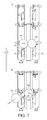
FIG. 7 illustrates a singulation process for two coins side by side on the conveyor; and
FIG. 8 shows capture of a coin on a downward descent of the conveyor.
DETAILED DESCRIPTION
Referring to FIG. 1, a money item handling device is shown, which in this example is operable to store and pay out coins of different denominations e.g. to provide change for a monetary transaction.
The device comprises a housing 1 which receives coins 2 of predetermined different denominations through an inlet 3, for example from coin acceptor devices which validate coins presented by a user during a vending transaction.
A continuous loop conveyor 4 is driven by a motor 5 to transport the coins 2 through the device for processing at one or more processing stations. The coins 2 are received on the conveyor at a receiving station 6 and tend to adopt a non-uniform, random stacked configuration at various angles in the station 6 where they fall onto the conveyor 4. As explained in more detail hereinafter, the conveyor is configured to transport the coins one by one i.e. in a singulated fashion along an elevating section 7 of the conveyor to a generally horizontal bridging section 8 which includes a processing station that includes coin sensor 9 and payout gates 10. Some coins may remain on the conveyor 4 after the payout gates 10 which pass along a descending section ii back to the receiving section 6.
As the conveyor 4 turns from the elevating section 7 to the bridging section 8, coins on the conveyor such as coin 2′, are transferred and moved along a support surface 13 by the conveyor 4 through the coin sensor 9. The coin sensor 9 may be an inductive sensor including coils (not shown) and/or optical sensors on one or both sides of the conveyor 4 to detect inductive and/or optical characteristics of the coin, which may be compared by a processor 14 with reference values held in a memory 15 to determine their authenticity and denomination.
The payout gates 10 may comprise solenoid operated gates controlled by the processor 14, which can be selectively lowered so that selected coins moving along the surface 13 that have been detected by the sensor 9 to be of a particular denomination can be discharged into one or more outlet chutes 16 to be returned to the user, for example as change for the transaction.
The conveyor 4 is made up of links illustrated in more detail in FIGS. 2 and 3, and comprises an alternating pattern of first and second link members 17, 18 that are pivotly connected to one another by grips 19 that engage shafts 20. The link members 17, 18 each include a generally planar money item receiving surface 21 which, in this example, receives coins, with the major discoidal surface of the coin 2 overlying the surface 21, as illustrated schematically in FIG. 4, with two coins of different diameters 2″ and 2″′ having respective major discoidal surfaces 22, 22′ bounded by respective peripheries 23, 23′.
The link members 17, 18 have a longitudinal central axis L-L′ and the conveyor is configured to move in a longitudinal conveyance direction C as shown in FIG. 2, along which the longitudinal axes of the link members 17, 18 are arranged.
Referring to FIG. 3, the link members 17, 18 are formed with a recessed driveable element, such as an integrally moulded toothed track 24 which, as shown in FIG. 1 engages with gear 25 driven by motor 5 so as to move the conveyor in the longitudinal conveying direction C. As shown in FIG. 3, the toothed track is recessed into the link members 17, 18. Also, each of the link members has protruding guide stubs 27 that extend transversely to the longitudinal conveying direction C to be received in a guide slot (not shown) extending around the path of the looped conveyor to guide the links around the path.
Also, as shown in FIG. 3, the links 17, 18 may include one or more recessed position locating elements for determining the position of the links 17, 18 with respect to a path of the track. The position locating elements mark the positions of each link 17, 18 and may comprise a recessed optical element, such as a light guide or light reflector. In the description below, the position locating elements are discussed in the context of reflective panels 28 which are recessed into the body of the links 17, 18 and may be detected by an optical detector 29 illustrated in FIG. 1, so as to count the link members 17 as they are conveyed around the conveyor loop.
Referring to FIG. 2, the first link members 17 include first and second lugs 30, 31 which are upstanding from the money item receiving surface 21 and are disposed on opposite sides of the longitudinal axis L-L′. The first and second lugs 30, 31 are configured to guide coins from the non-uniform stack that occurs in the receiving section 6 shown in FIG. 1 into the location on the conveyor 4 shown in FIG. 4, with a single coin captured between the lugs 30, 31, overlying the money item receiving surface 21.
As shown clearly in FIG. 2, the first lug 30 has a forward facing capture region 33 in the form of trapezoidal surface which forms an angle θ with longitudinal axis L-L′ in the conveying direction C, with a height that increases outwardly from the longitudinal axis. The surface 33 forms a capture edge 34 with the main body of the lug 30 of a height h1 which is not more than the minimum thickness of the various, predetermined acceptable denominations of coins that enter the receiving section 6 of FIG. 1. For example, the height of the capture edge 34 may be less than 1.2 mm, typically 1.0 mm.
The maximum height h2 of the trapezoidal surface 33 is typical three or four times greater than the minimum height h1 so as to engage with coins in the non-uniform stack of the receiving section 6 and encourage one of them to lie flat on the money item receiving section 21 between the lugs 30, 31 as the conveyor 4 passes through the receiving section 6 in the longitudinal conveying direction C.
The second lug 31 has a coin capture region in the form of an upstanding coin edge 35 at the join of first and second guide surfaces 36, 37 that are upstanding from the money item receiving surface 21 and diverge rearwardly with respect to the longitudinal conveying direction C. The capture edge 35 of lug 31 is of a height edge h3 which is less than the minimum thickness of the coins 2 received in the receiving section 6 and may for example be equal to the height h1 of the first lug 30. For example, the height of the capture edge 35 may be less than 1.2 mm, typically 1.0 mm.
Thus, when each of the first link members 17 passes through the coin receiving section 6 shown in FIG. 1 the coin capture regions 33, 35 co-operate to capture a single coin from the non-uniform stack of coins in the receiving section 6 such that the captured coin becomes located between the capture edges 34, 35, overlying the money item receiving surface 21.
The lugs 30, 31 are configured to capture only one coin 2 from the stack as will now be explained with reference to FIGS. 5 and 6. As shown in FIG. 6, the lugs 30, 31 include scoop surfaces comprising a generally triangular, chined surface 38 on the first lug 30 together with a chined, scoop surface 38′ on the second lug 31, so that, as shown in FIG. 6, when two coins 2-1, 2-2 become lodged in a stack during the coin capture process at the receiving station 6, the forward movement of the conveyor in direction C causes the uppermost coin 2-2 in the stack to slide over the scoop surfaces 38, 38′ in the direction of arrow X so that only the lowermost coin 2-1 is retained between the coin capture edges 34, 35.
Referring to FIG. 7, the first and second lugs 30, 31 are also configured to prevent two smaller coins becoming lodged side by side on the money item receiving surface 21 as the link members 17,18 pass through the coin receiving section 6. As shown in FIG. 7A, two coins 2 a, 2 b have become lodged against the first and second lugs 30, 31 during the coin capture process in the coin receiving section 6. Considering the coin 2 a, it has been captured against the upstanding surface 34, which is inclined at angle θ to the longitudinal axis L-L′ as shown in FIG. 4, so that as the conveyor moves forward in direction C, the coin 2A shown in FIG. 7A is urged against the coin 2B in the direction of arrow Y by a transverse reaction force produced by engagement with the lug 30, which urges the coin 2B out of engagement with the capture edge 35 of the second lug 31. As shown in FIG. 4, the surface 36 of the second lug 31 is inclined at angle α to the longitudinal axis L-L′ so that, as shown in FIG. 7B, the coin 2B then moves along the surface 36 in the direction of arrow Z and the coin 2A then moves into a position captured between the capture edges 34, 35 of the first and second lugs 30, 31.
Also, as shown clearly in FIG. 2, each second link member 18 includes an upstanding lug 39 which is located to prevent two large coins such as two of the coin denomination 2′″ shown in FIG. 4 becoming jammed between the successive pairs of lugs 30, 31 shown in FIG. 4.
Referring to FIG. 8, the first and second lugs 30, 31 also include inwardly inclined, upstanding support surfaces 40, 41 that are facing rearwardly of the longitudinal conveying direction C, on opposite sides of the longinitudianl axis L-L′ so that when a coin captured between the capture edges 34, 35 of first and second lugs 30, 31, after being slid over the horizontal surface of the bridging region 13 and entering the descending section 11, the coin 2C falls and slides over the surface 21 to abut the inclined surfaces 40, 41, so as to be retained on the conveyor during its descend through the descending section ii shown in FIG. 1.
Many modifications and variations of the described device are possible. For example, the coin handling device may be used not only for vending but also in casinos and other situations where coins or money item items such as tokens need to be processed. Moreover, the disclosure of the present application should be understood to include any novel features or any novel combination of features either explicitly or implicitly disclosed herein or in any generalisation thereof and during prosecution of the present application or of any application derived therefrom, new claims may be formulated to cover any such features and/or combination of such features. Many other variations will be evident to those skilled in the art falling within the scope of the claims hereinafter.

Claims (16)

The invention claimed is:
1. A handling device for money items having a generally discoidal surface and a peripheral edge, the handling device comprising:
a receiving station configured to receive money items supplied thereto, a money item processing station; and
a conveyor configured to convey money items from the money item receiving station to the money item processing station, the conveyor comprising:
a conveyor member having a money item receiving surface, and
first and second lugs upstanding from said money item receiving surface, the first lug comprising a forward facing first capture region and the second lug comprising a forward facing second capture region, the capture regions configured to be driven in a longitudinal conveying direction through the money item receiving station to receive a money item with its major discoidal surface overlying the money item receiving surface and with its peripheral edge abutting the capture regions of the lugs, one of the capture regions of the lugs being upstanding from said money item receiving surface at least in part by a height greater than the other capture region,
wherein the capture regions are arranged such that if first and second of said money items become lodged on the money item receiving surface and abutting the first and second capture regions respectively, upon forward movement of the conveyor in the longitudinal conveying direction, the first money item is urged by the first capture region against the second money item so as to dislodge the second money item from abutment with the second capture region so that solely the first money item is held in abutment with the first and second capture regions,
wherein the first and second lugs are disposed on opposite sides of a longitudinal axis of the conveyor member, and the first capture region of the first lug comprises a capture surface facing forwardly in said longitudinal conveying direction, having a height which reduces in a direction of said longitudinal axis, and
wherein the capture surface is trapezoidal and forms an acute angle with the longitudinal axis in the longitudinal conveying direction and with a height that increases outwardly from the longitudinal axis.
2. The handling device as claimed in claim 1, wherein the receiving station is configured to receive a plurality of money items of different dimensions that comprise opposed, spaced apart, generally discoidal major surfaces with a thickness dimension between the major surfaces falling within a predetermined thickness range having a minimum thickness value, wherein a maximum height by which the capture regions of first and second lugs are each upstanding from the money item receiving surface is more than said minimum thickness value and less than said minimum thickness value respectively.
3. The handling device as claimed in claim 1, wherein the second capture region comprises an upstanding capture edge at a join of a first guide surface and a second guide surface that are upstanding from the money item receiving surface and diverge rearwardly with respect to said longitudinal conveying direction.
4. The handling device as claimed in claim 1, comprising at least one scoop surface on at least one of the first and second lugs, so arranged that if first and second of said money items become arranged in a stack in engagement with the capture region of the first lug, an upper one of the money items is guided by the at least one scoop surface to pass by the lugs upon forward movement of the conveyor in said longitudinal conveying direction such that solely a lowermost money item in the stack abuts the first and second capture regions.
5. The handling device as claimed in claim 4, wherein the at least one scoop surface diverges from the money item receiving surface rearwardly of said longitudinal conveying direction.
6. The handling device as claimed in claim 1, wherein the height of the second capture region is less than 1.2 mm and the height of the first capture region is at least in part greater than that of the second capture region.
7. The handling device as claimed in claim 1, wherein the height of the second capture region is less than 1.0 mm and the height of the first capture region is at least in part greater than that of the second capture region.
8. The handling device as claimed in claim 1, further comprising a plurality of said conveyor members pivotally connected and provided with a respective set of said first and second lugs.
9. The handling device as claimed in claim 1, wherein the conveyor is configured in a continuous loop comprising an elevating section extending from the money item receiving section to a processing section, and a descending section extending back to a receiving section, the first and second capture regions being configured to hold a single one of the money items during passage of the conveyor along the elevating section.
10. The handling device as claimed in claim 9, wherein the first and second lugs include respective support surfaces facing rearwardly in said longitudinal conveying direction for supporting a money item that remains on the conveyor after passage through the money item processing station during conveyance along the descending section.
11. The handling device as claimed in claim 1, including a driveable element recessed in said conveyor member, and a motor driven gear engaging with a track to drive the conveyor.
12. The handling device as claimed in claim 11, wherein the driveable element comprises a toothed track recessed in said conveyor member.
13. A conveyor to receive and convey money items having a generally discoidal surface and a peripheral edge, comprising a conveyor member including:
a money item receiving surface; and
first and second lugs upstanding from said money item receiving surface, the first lug comprising a forward facing first capture region and the second lug comprising a forward facing second capture region, the capture regions configured to be driven in a longitudinal conveying direction through a money item receiving station to receive a money item with its major discoidal surface overlying the money item receiving surface and with its peripheral edge abutting the capture regions of the lugs, one of the capture regions of the lugs being upstanding from said money item receiving surface at least in part by a height greater than the other capture region, and the capture regions being so arranged that if first and second of said money items become lodged on the money item receiving surface and abutting the first and second capture regions respectively, upon forward movement of the conveyor in the longitudinal conveying direction, the first money item is urged by the first capture region against the second money item so as to dislodge the second money item from abutment with the second capture region so that solely the first money item is held in abutment with the first and second capture regions,
wherein the first and second lugs are disposed on opposite sides of a longitudinal axis of the conveyor member, and the first capture region of the first lug comprises a capture surface facing forwardly in said longitudinal conveying direction, having a height which reduces in the direction of said longitudinal axis, and
wherein the capture surface is trapezoidal and forms an acute angle with the longitudinal axis of the conveying member in the longitudinal conveying direction and with a height that increases outwardly from the longitudinal axis.
14. The conveyor as claimed in claim 13, wherein the second capture region comprises an upstanding capture edge at a join of first and second guide surfaces that are upstanding from the money item receiving surface and diverge rearwardly in said longitudinal conveying direction.
15. The conveyor as claimed in claim 13, including at least one scoop surface on each of the first and second lugs so arranged that if first and second of said money items become arranged in a stack in engagement with the capture region of the first lug, an upper one of the money items is guided by each said scoop surface to pass by the lugs upon forward movement of the conveyor in said longitudinal conveying direction such that solely a lowermost money item in the stack abuts the first and second capture regions.
16. The conveyor as claimed in claim 15, wherein the scoop surfaces diverge from the money item receiving surface rearwardly of said longitudinal conveying direction.
US15/326,645 2014-07-16 2015-06-29 Money item handling device and conveyor Active US10192384B2 (en)

Applications Claiming Priority (3)

Application Number Priority Date Filing Date Title
GB1412633.8A GB2528287A (en) 2014-07-16 2014-07-16 Money item handling device and conveyor
GB1412633.8 2014-07-16
PCT/GB2015/051886 WO2016009172A1 (en) 2014-07-16 2015-06-29 Money item handling device and conveyor

Publications (2)

Publication Number Publication Date
US20170206729A1 US20170206729A1 (en) 2017-07-20
US10192384B2 true US10192384B2 (en) 2019-01-29

Family

ID=51454218

Family Applications (1)

Application Number Title Priority Date Filing Date
US15/326,645 Active US10192384B2 (en) 2014-07-16 2015-06-29 Money item handling device and conveyor

Country Status (7)

Country Link
US (1) US10192384B2 (en)
EP (1) EP3170155B1 (en)
CN (1) CN106796741B (en)
AU (1) AU2015288956B2 (en)
ES (1) ES2963333T3 (en)
GB (1) GB2528287A (en)
WO (1) WO2016009172A1 (en)

Families Citing this family (4)

* Cited by examiner, † Cited by third party
Publication number Priority date Publication date Assignee Title
JP6756282B2 (en) * 2017-03-16 2020-09-16 富士電機株式会社 Coin check device
JP6505298B1 (en) 2018-06-28 2019-04-24 日本金銭機械株式会社 Paper processing device
GB201915439D0 (en) * 2019-10-24 2019-12-11 Crane Payment Innovations Ltd Money item handling system and method
GB2590425B (en) 2019-12-17 2021-12-29 Innovative Tech Ltd A coin elevator mechanism

Citations (15)

* Cited by examiner, † Cited by third party
Publication number Priority date Publication date Assignee Title
US3463171A (en) * 1966-10-06 1969-08-26 Brecknell Dolman & Rogers Ltd Apparatus for extracting and feeding coins stored in a bulk supply
US4535794A (en) * 1981-11-20 1985-08-20 Coin Controls Limited Machine having a coin or token payout mechanism
US6328646B1 (en) * 1999-02-24 2001-12-11 Asahi Seiko Co., Ltd. Coin hopper transportation with endless belt conveyor
US20030032387A1 (en) * 2001-08-08 2003-02-13 Hiroshi Abe Coin dispensing apparatus with removable auxiliary storage unit
US6579166B2 (en) * 2000-01-28 2003-06-17 Asahi Seiko Co., Ltd Coin hopper with peripheral coin transport device
US20050277378A1 (en) * 2004-06-09 2005-12-15 Novotech Elektronik Gesellschaft M.B.H. Apparatus for separating coins
US20090008215A1 (en) * 2004-07-07 2009-01-08 Money Controls Limited "money item dispensing apparatus"
WO2009030651A2 (en) 2007-09-06 2009-03-12 Money Controls Limited Coin mechanism
US20100203817A1 (en) * 2007-04-11 2010-08-12 Fabrizio Rigo Machine for accepting and distributing coins and/or tokens
US20100227539A1 (en) * 2009-03-05 2010-09-09 Azkoyen Medios De Pago, S.A. Coin dispenser
US20110105002A1 (en) * 2009-11-02 2011-05-05 Ernst Blaha Chip Sorting Devices, Components Therefor and Methods of Ejecting Chips
GB2485395A (en) 2010-11-12 2012-05-16 Money Controls Ltd Coin conveying apparatus
US20140194045A1 (en) * 2011-04-07 2014-07-10 Wincor Nixdorf International Gmbh Apparatus and method for sorting coins
GB2513539A (en) 2013-02-04 2014-11-05 Crane Payment Solutions Ltd Conveying money items
EP2801957A1 (en) 2013-05-08 2014-11-12 Outerwall Inc. Coin counting and/or sorting machines and associated systems and methods

Family Cites Families (1)

* Cited by examiner, † Cited by third party
Publication number Priority date Publication date Assignee Title
JP2006338593A (en) * 2005-06-06 2006-12-14 Nippon Conlux Co Ltd Bill handling device

Patent Citations (22)

* Cited by examiner, † Cited by third party
Publication number Priority date Publication date Assignee Title
US3463171A (en) * 1966-10-06 1969-08-26 Brecknell Dolman & Rogers Ltd Apparatus for extracting and feeding coins stored in a bulk supply
US4535794A (en) * 1981-11-20 1985-08-20 Coin Controls Limited Machine having a coin or token payout mechanism
US6328646B1 (en) * 1999-02-24 2001-12-11 Asahi Seiko Co., Ltd. Coin hopper transportation with endless belt conveyor
US6579166B2 (en) * 2000-01-28 2003-06-17 Asahi Seiko Co., Ltd Coin hopper with peripheral coin transport device
US20030032387A1 (en) * 2001-08-08 2003-02-13 Hiroshi Abe Coin dispensing apparatus with removable auxiliary storage unit
US6761627B2 (en) * 2001-08-08 2004-07-13 Asahi Seiko Co., Ltd. Coin dispensing apparatus with removable auxiliary storage unit
US20050277378A1 (en) * 2004-06-09 2005-12-15 Novotech Elektronik Gesellschaft M.B.H. Apparatus for separating coins
US20090008215A1 (en) * 2004-07-07 2009-01-08 Money Controls Limited "money item dispensing apparatus"
US20120261434A1 (en) * 2004-07-07 2012-10-18 Money Controls Limited Money Item Dispensing Apparatus
US20100203817A1 (en) * 2007-04-11 2010-08-12 Fabrizio Rigo Machine for accepting and distributing coins and/or tokens
CN101796552A (en) 2007-09-06 2010-08-04 货币控制有限公司 Coin mechanism
US20100210200A1 (en) * 2007-09-06 2010-08-19 Money Controls Limited Coin mechanism
WO2009030651A2 (en) 2007-09-06 2009-03-12 Money Controls Limited Coin mechanism
US20100227539A1 (en) * 2009-03-05 2010-09-09 Azkoyen Medios De Pago, S.A. Coin dispenser
US20110105002A1 (en) * 2009-11-02 2011-05-05 Ernst Blaha Chip Sorting Devices, Components Therefor and Methods of Ejecting Chips
GB2485395A (en) 2010-11-12 2012-05-16 Money Controls Ltd Coin conveying apparatus
US20120122385A1 (en) * 2010-11-12 2012-05-17 Watson Mark J Coin apparatus
US8840450B2 (en) * 2010-11-12 2014-09-23 Money Controls Limited Coin apparatus
US20140194045A1 (en) * 2011-04-07 2014-07-10 Wincor Nixdorf International Gmbh Apparatus and method for sorting coins
GB2513539A (en) 2013-02-04 2014-11-05 Crane Payment Solutions Ltd Conveying money items
EP2801957A1 (en) 2013-05-08 2014-11-12 Outerwall Inc. Coin counting and/or sorting machines and associated systems and methods
US9183687B2 (en) * 2013-05-08 2015-11-10 Outerwall Inc. Coin counting and/or sorting machines and associated systems and methods

Non-Patent Citations (4)

* Cited by examiner, † Cited by third party
Title
Communication from a foreign patent office in a counterpart foreign application, State Intellectual Property Office of the Peoples Republic of China, "Notification of the First Office Action (PCT Application Entry into the National Phase)," Application No. CN201580036221.7, dated Aug. 27, 2018, 23 pages.
Search Report dated Jan. 20, 2015 in connection with British Application No. 1412633.8, 2 pages.
Search Report dated Jan. 20, 2015 in connection with British Application No. 1412633.8, 4 pages.
Transmittal of the International Search Report and the Written Opinion of the International Searching Authority dated Sep. 15, 2015, 10 pages.

Also Published As

Publication number Publication date
GB2528287A (en) 2016-01-20
CN106796741A (en) 2017-05-31
GB201412633D0 (en) 2014-08-27
EP3170155B1 (en) 2023-11-08
EP3170155A1 (en) 2017-05-24
WO2016009172A1 (en) 2016-01-21
AU2015288956B2 (en) 2020-11-26
CN106796741B (en) 2019-07-09
ES2963333T3 (en) 2024-03-26
US20170206729A1 (en) 2017-07-20
AU2015288956A1 (en) 2017-01-12

Similar Documents

Publication Publication Date Title
US10192384B2 (en) Money item handling device and conveyor
EP3023367B1 (en) Coin carrying and guiding device of coin payment apparatus
US12118844B2 (en) Coin receiving and dispensing device, coin lifting device, and coin lifting device of coin receiving and dispensing device
TWI734239B (en) Coin conveying device and coin conveying device of coin receiving and discharging device
JP6956418B2 (en) Coin identification and transport device
JP2014191804A (en) Coin ejection device and coin processing device
JP5178412B2 (en) Bar metal storage device
JP4784807B2 (en) Coin handling equipment
JP7342549B2 (en) coin conveyor
JP6404651B2 (en) Coin handling equipment
JP6540244B2 (en) Coin sorting apparatus and coin handling apparatus
TW202025096A (en) Coin deposit/disbursal device
JP7294015B2 (en) coin sorting device
JP4294439B2 (en) Coin storage device
JP6321417B2 (en) Deposit machine and design method thereof
WO2018101173A1 (en) Coin delivery device
US20160260275A1 (en) Rapid conveyance of coins by rotating conveyor belts
JP5945786B2 (en) Coin transport / dispensing device
JP2018092257A (en) Coin delivery device
JP2018092258A (en) Coin delivery device
WO2020012532A1 (en) Coin processing device
JP2017151558A (en) Coin processor
JP2002352294A (en) Coin sorting device and vending machine
JPWO2019130440A1 (en) Endless transport belt and coin processing equipment
JP2000067291A (en) Coin sorting equipment

Legal Events

Date Code Title Description
AS Assignment

Owner name: CRANE PAYMENT INNOVATIONS LIMITED, GREAT BRITAIN

Free format text: ASSIGNMENT OF ASSIGNORS INTEREST;ASSIGNORS:BLYTHIN, ROBERT JAMES;BARSON, ANDREW;TAYLOR, DAVID;SIGNING DATES FROM 20180109 TO 20180111;REEL/FRAME:044917/0900

AS Assignment

Owner name: CRANE PAYMENT INNOVATIONS LIMITED, GREAT BRITAIN

Free format text: CHANGE OF NAME;ASSIGNOR:CRANE PAYMENT SOLUTIONS LIMITED;REEL/FRAME:046424/0776

Effective date: 20160902

STCF Information on status: patent grant

Free format text: PATENTED CASE

MAFP Maintenance fee payment

Free format text: PAYMENT OF MAINTENANCE FEE, 4TH YEAR, LARGE ENTITY (ORIGINAL EVENT CODE: M1551); ENTITY STATUS OF PATENT OWNER: LARGE ENTITY

Year of fee payment: 4