US10184359B2 - Waste heat recovery device and waste heat recovery method - Google Patents
Waste heat recovery device and waste heat recovery method Download PDFInfo
- Publication number
- US10184359B2 US10184359B2 US14/662,701 US201514662701A US10184359B2 US 10184359 B2 US10184359 B2 US 10184359B2 US 201514662701 A US201514662701 A US 201514662701A US 10184359 B2 US10184359 B2 US 10184359B2
- Authority
- US
- United States
- Prior art keywords
- working medium
- heater
- heat exchanger
- engine
- flowed out
- Prior art date
- Legal status (The legal status is an assumption and is not a legal conclusion. Google has not performed a legal analysis and makes no representation as to the accuracy of the status listed.)
- Expired - Fee Related, expires
Links
- 238000011084 recovery Methods 0.000 title claims abstract description 61
- 239000002918 waste heat Substances 0.000 title claims abstract description 59
- 238000000034 method Methods 0.000 title claims description 16
- 238000010438 heat treatment Methods 0.000 claims abstract description 45
- 239000007789 gas Substances 0.000 claims description 21
- 230000007423 decrease Effects 0.000 claims description 19
- 238000001704 evaporation Methods 0.000 claims description 6
- 238000001514 detection method Methods 0.000 description 9
- 238000010586 diagram Methods 0.000 description 8
- 239000007788 liquid Substances 0.000 description 5
- 239000002826 coolant Substances 0.000 description 3
- 238000012986 modification Methods 0.000 description 3
- 230000004048 modification Effects 0.000 description 3
- 238000001816 cooling Methods 0.000 description 2
- 230000003247 decreasing effect Effects 0.000 description 2
- 239000013535 sea water Substances 0.000 description 2
- 238000011144 upstream manufacturing Methods 0.000 description 2
- 238000009834 vaporization Methods 0.000 description 1
- 230000008016 vaporization Effects 0.000 description 1
Images


Classifications
-
- F—MECHANICAL ENGINEERING; LIGHTING; HEATING; WEAPONS; BLASTING
- F01—MACHINES OR ENGINES IN GENERAL; ENGINE PLANTS IN GENERAL; STEAM ENGINES
- F01K—STEAM ENGINE PLANTS; STEAM ACCUMULATORS; ENGINE PLANTS NOT OTHERWISE PROVIDED FOR; ENGINES USING SPECIAL WORKING FLUIDS OR CYCLES
- F01K23/00—Plants characterised by more than one engine delivering power external to the plant, the engines being driven by different fluids
- F01K23/02—Plants characterised by more than one engine delivering power external to the plant, the engines being driven by different fluids the engine cycles being thermally coupled
-
- F—MECHANICAL ENGINEERING; LIGHTING; HEATING; WEAPONS; BLASTING
- F01—MACHINES OR ENGINES IN GENERAL; ENGINE PLANTS IN GENERAL; STEAM ENGINES
- F01K—STEAM ENGINE PLANTS; STEAM ACCUMULATORS; ENGINE PLANTS NOT OTHERWISE PROVIDED FOR; ENGINES USING SPECIAL WORKING FLUIDS OR CYCLES
- F01K13/00—General layout or general methods of operation of complete plants
- F01K13/02—Controlling, e.g. stopping or starting
-
- F—MECHANICAL ENGINEERING; LIGHTING; HEATING; WEAPONS; BLASTING
- F01—MACHINES OR ENGINES IN GENERAL; ENGINE PLANTS IN GENERAL; STEAM ENGINES
- F01K—STEAM ENGINE PLANTS; STEAM ACCUMULATORS; ENGINE PLANTS NOT OTHERWISE PROVIDED FOR; ENGINES USING SPECIAL WORKING FLUIDS OR CYCLES
- F01K23/00—Plants characterised by more than one engine delivering power external to the plant, the engines being driven by different fluids
- F01K23/02—Plants characterised by more than one engine delivering power external to the plant, the engines being driven by different fluids the engine cycles being thermally coupled
- F01K23/06—Plants characterised by more than one engine delivering power external to the plant, the engines being driven by different fluids the engine cycles being thermally coupled combustion heat from one cycle heating the fluid in another cycle
- F01K23/065—Plants characterised by more than one engine delivering power external to the plant, the engines being driven by different fluids the engine cycles being thermally coupled combustion heat from one cycle heating the fluid in another cycle the combustion taking place in an internal combustion piston engine, e.g. a diesel engine
-
- F—MECHANICAL ENGINEERING; LIGHTING; HEATING; WEAPONS; BLASTING
- F01—MACHINES OR ENGINES IN GENERAL; ENGINE PLANTS IN GENERAL; STEAM ENGINES
- F01K—STEAM ENGINE PLANTS; STEAM ACCUMULATORS; ENGINE PLANTS NOT OTHERWISE PROVIDED FOR; ENGINES USING SPECIAL WORKING FLUIDS OR CYCLES
- F01K23/00—Plants characterised by more than one engine delivering power external to the plant, the engines being driven by different fluids
- F01K23/18—Plants characterised by more than one engine delivering power external to the plant, the engines being driven by different fluids characterised by adaptation for specific use
-
- F—MECHANICAL ENGINEERING; LIGHTING; HEATING; WEAPONS; BLASTING
- F02—COMBUSTION ENGINES; HOT-GAS OR COMBUSTION-PRODUCT ENGINE PLANTS
- F02B—INTERNAL-COMBUSTION PISTON ENGINES; COMBUSTION ENGINES IN GENERAL
- F02B29/00—Engines characterised by provision for charging or scavenging not provided for in groups F02B25/00, F02B27/00 or F02B33/00 - F02B39/00; Details thereof
- F02B29/04—Cooling of air intake supply
- F02B29/0406—Layout of the intake air cooling or coolant circuit
- F02B29/0437—Liquid cooled heat exchangers
- F02B29/0443—Layout of the coolant or refrigerant circuit
-
- F—MECHANICAL ENGINEERING; LIGHTING; HEATING; WEAPONS; BLASTING
- F02—COMBUSTION ENGINES; HOT-GAS OR COMBUSTION-PRODUCT ENGINE PLANTS
- F02G—HOT GAS OR COMBUSTION-PRODUCT POSITIVE-DISPLACEMENT ENGINE PLANTS; USE OF WASTE HEAT OF COMBUSTION ENGINES; NOT OTHERWISE PROVIDED FOR
- F02G5/00—Profiting from waste heat of combustion engines, not otherwise provided for
-
- Y—GENERAL TAGGING OF NEW TECHNOLOGICAL DEVELOPMENTS; GENERAL TAGGING OF CROSS-SECTIONAL TECHNOLOGIES SPANNING OVER SEVERAL SECTIONS OF THE IPC; TECHNICAL SUBJECTS COVERED BY FORMER USPC CROSS-REFERENCE ART COLLECTIONS [XRACs] AND DIGESTS
- Y02—TECHNOLOGIES OR APPLICATIONS FOR MITIGATION OR ADAPTATION AGAINST CLIMATE CHANGE
- Y02T—CLIMATE CHANGE MITIGATION TECHNOLOGIES RELATED TO TRANSPORTATION
- Y02T10/00—Road transport of goods or passengers
- Y02T10/10—Internal combustion engine [ICE] based vehicles
- Y02T10/12—Improving ICE efficiencies
-
- Y02T10/144—
-
- Y02T10/146—
-
- Y02T10/166—
Definitions
- the present invention relates to a waste heat recovery device and a waste heat recovery method.
- Japanese Unexamined Patent Publication No. 2013-167241 discloses a waste heat recovery device, including: a heat exchanger which evaporates an working medium by exchanging heat between pressurized intake air and an working medium; an expander which expands the working medium which has flowed out from the heat exchanger; a power generator connected to the expander; a condenser which condenses the working medium which has flowed out from the expander; a pump which sends the working medium which has flowed out from the condenser, to the heat exchanger; and a controller which controls the number of revolutions of the pump in accordance with the thermal load on the heat exchanger.
- the controller increases the number of revolutions of the pump on the basis of previously stored information. Consequently, the amount of waste heat recovered (the amount of electric power generated by the power generator) is increased.
- the thermal load becomes smaller, the number of revolutions of the pump is reduced on the basis of the information. In other words, the vaporization of the working medium in the heat exchanger is prioritized.
- An object of the present invention is to provide a waste heat recovery device and a waste heat recovery method whereby waste heat can be recovered stably in a broad range from a low engine load to a high engine load.
- the waste heat recovery device includes: a heater which evaporates an working medium by exchanging heat between supercharging air supplied to the engine and the working medium; a heat exchanger which heats the working medium by exchanging heat between the working medium which has flowed out from the heater, and a heating medium; an expander which expands the working medium which has flowed out from the heat exchanger; a motive power recovery device which is connected to the expander; a condenser which condenses the working medium which has flowed out from the expander; and a pump which sends the working medium which has flowed out from the condenser, to the heater.
- the waste heat recovery method is a method for recovering the waste heat of the supercharging air supplied to the engine.
- This waste heat recovery method includes: an evaporating step for evaporating an working medium by a heater, by supplying the supercharging air to the heater; a heating step for heating the working medium by exchanging heat between the working medium which has flowed out from the heater and a heating medium in use of a heat exchanger; a motive power recovery step for recovering motive power from the working medium, by expanding the working medium which has flowed out from the heat exchanger in use of an expander; a condensing step for condensing the working medium which has flowed out from the expander in use of a condenser; and a pump driving step for sending in use of a pump the working medium which has flowed out from the condenser to the heater.
- the pump driving step the number of revolutions of the pump is increased and reduced in accordance with increase and decrease in a differential pressure between pressure of the superchar
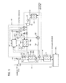
- FIG. 1 is a diagram showing an overview of the configuration of a waste heat recovery device according to one embodiment of the present invention
- FIG. 2 is a diagram showing a relationship between a load on an engine and a flow volume of supercharging air
- FIG. 3 is a diagram showing a relationship between a differential pressure and a flow volume of supercharging air
- FIG. 4 is a diagram showing a relationship between a differential pressure and the number of revolutions of a pump
- FIG. 5 is a diagram showing a relationship between a flow volume of supercharging air and a flow volume of an working medium, and a relationship between a flow volume of supercharging air and a differential pressure of a pump;
- FIG. 6 is a diagram showing pump characteristics and a resistance curve of a pump
- FIG. 7 is a flowchart showing control contents of a controller.
- FIG. 8 is a flowchart showing control contents of a controller.
- the waste heat recovery device 10 according to one embodiment of the present invention is described here with reference to FIG. 1 .
- the waste heat recovery device 10 includes: a heater 12 , a heat exchanger 14 , an expander 16 , a motive power recovery device 18 , a condenser 20 , a pump 22 , a circulation flow channel 24 which connects the heater 12 , the heat exchanger 14 , the expander 16 , the condenser 20 and the pump 22 , serially in this order, and a controller 30 which implements various controls.
- the waste heat recovery device 10 according to the present embodiment is installed in a ship and recovers waste heat from an engine equipped with a supercharger.
- the supercharger-equipped engine has a supercharger, an engine 3 , air intake lines 32 , 35 , an exhaust line 37 , and a gas cooler 2 provided in the air intake line.
- the supercharger has a compressor 1 and a turbine 4 connected to this compressor 1 .
- the supercharging air which has been compressed by the compressor 1 is supplied to the gas cooler 2 via the air intake line, and is cooled in the gas cooler.
- seawater for example, is used as a cooling medium for cooling the supercharging air.
- Supercharging air which has flowed out from the gas cooler 2 is supplied to the engine 3 via the air intake line.
- the exhaust gas of the engine 3 is sent to the turbine 4 via the exhaust line 37 .
- the turbine 4 is driven by the expansion energy of the exhaust gas, and the compressor 1 is driven by the drive force of the turbine 4 .
- the waste heat recovery device 10 recovers waste heat from the supercharging air, due to the heater 12 being connected to a portion of the air intake line between the compressor 1 and the gas cooler 2 .
- the heater 12 evaporates an working medium by exchanging heat between the working medium in liquid form, and the supercharging air which is compressed by the compressor 1 . More specifically, the heater 12 has a first flow channel 12 a in which supercharging air supplied from the compressor 1 via a first pipe 32 of the air intake line flows, and a second flow channel 12 b in which the working medium flows. The supercharging air which has flowed out from the heater 12 flows in to the gas cooler 2 via a second pipe 35 of the air intake line.
- the heat exchanger 14 is provided in a portion of the circulation flow channel 24 to the downstream side of the heater 12 . Furthermore, the heat exchanger 14 is connected to a steam line which is provided inside the ship. The heat exchanger 14 heats the working medium by exchanging heat between the working medium which has flowed out from the heater 12 and surplus steam (a heating medium) generated by the ship. More specifically, the heat exchanger 14 has a first flow channel 14 a in which steam supplied via the steam supply pipe (heating medium supply pipe) 26 flows, and a second flow channel 14 b in which the working medium flows. An adjustment valve 28 of which the degree of opening being adjustable, and a pressure sensor 29 , are provided in the steam supply pipe 26 .
- the flow rate and the pressure of the steam supplied from the steam supply pipe 26 to the heat exchanger 14 varies in accordance with the degree of opening of the adjustment valve 28 .
- a steam trap 27 may be arranged in a steam outlet pipe from the heat exchanger 14 . Since the amount of steam that is condensed in the heat exchanger 14 is determined, then the flow volume of the steam is adjusted automatically by arranging the steam trap 27 .
- a shell and tube heat exchanger or a plate-type heat exchanger may be used as the heat exchanger 14 .
- the expander 16 is provided in a portion of the circulation flow channel 24 to the downstream side of the heat exchanger 14 .
- a volume-type screw expander having a rotor which is driven to rotate by the expansion energy of an working medium in gas form which has flowed out from the heat exchanger 14 is used as the expander 16 .
- this expander 16 has a casing inside which a rotor chamber is formed, and a male/female pair of screw rotors which are supported rotatably inside the rotor chamber.
- the screw rotor is driven to rotate by the expansion energy of the working medium in gas form supplied to the rotor chamber from an air intake port formed in the casing.
- the working medium of which the pressure has been reduced by expansion inside the rotor chamber is discharged into the circulation flow channel 24 from an exhaust port formed in the casing.
- the expander 16 is not limited to being a volume-type screw expander, and it is also possible to use a centrifugal or scroll type expander.
- the motive power recovery device 18 is connected to the expander 16 .
- a power generator is used as the motive power recovery device 18 .
- This motive power recovery device 18 has a rotary shaft which is connected to one of the pair of screw rotors of the expander 16 .
- the motive power recovery device 18 generates electric power due to the rotary shaft rotating with the rotation of the screw rotor.
- a compressor or the like, as the motive power recovery device 18 .
- the condenser 20 is provided in a portion of the circulation flow channel 24 to the downstream side of the expander 16 .
- the condenser 20 condenses (liquefies) the working medium by cooling same by a cooling medium. Seawater, for example, is used as a cooling medium which is supplied to the condenser 20 .
- the pump 22 is provided in a portion of the circulation flow channel 24 to the downstream side of the condenser 20 (a portion between the heater 12 and the condenser 20 ).
- the pump 22 pressurizes the working medium in liquid form which has been condensed by the condenser 20 , to a prescribed pressure, and sends the working medium out to the downstream side of the pump 22 in the circulation flow channel 24 .
- a centrifugal pump provided with an impeller as a rotor, or a gear pump having a rotor formed of a pair of gears, or the like, is used as the pump 22 .
- the controller 30 increases and decreases the number of revolutions (frequency) of the pump 22 in accordance with the increase and decrease in the load of the engine 3 . Since the flow volume of the supercharging air which flows into the heater 12 (the amount of heat input to the heater 12 ) is increased and decreased in accordance with increase and decrease in the load of the engine 3 , then it is possible to recover the waste heat in the heater 12 efficiently by increasing and decreasing the number of revolutions of the pump 22 (extracting motive power in the motive power recovery device 18 ), accordingly.
- the controller 30 increases and decreases the number of revolutions of the pump 22 in accordance with increase and decrease in a differential pressure ⁇ P between the pressure of the supercharging air before flowing into the heater 12 and the pressure of the supercharging air after having flowed out from the heater 12 .
- the differential pressure ⁇ P is calculated by subtracting the detection value of a second pressure sensor 36 provided in a second pipe 35 which is positioned to the downstream side of the heater 12 in the air intake line, from the detection value of the first pressure sensor 33 provided in a first pipe 32 which is positioned to the upstream side of the heater 12 in the air intake line.
- FIG. 4 a relationship between the differential pressure ⁇ P and the optimal frequency (number of revolutions) of the pump 22 with respect to the differential pressure ⁇ P is calculated in advance.
- Information representing a relationship between the differential pressure ⁇ P and the optimal frequency (number of revolutions) of the pump is stored in the controller 30 . Consequently, it is possible to recover the motive power efficiently in accordance with the load on the engine 3 , by controlling the number of revolutions of the pump 22 so as to become a number of revolutions determined on the basis of the information stored in the controller 30 .
- the information in FIG. 4 (the information representing the relationship between the differential pressure ⁇ P and the optimal frequency of the pump) is determined from FIG. 3 , FIG. 5 and FIG. 6 .
- FIG. 4 the information representing the relationship between the differential pressure ⁇ P and the optimal frequency of the pump
- FIG. 5 is a diagram showing the increase in the flow volume of the working medium and the differential pressure of the pump 22 , in such a manner that the degree of superheating of the working medium is optimal in accordance with the increase in the flow volume of the supercharging air.
- FIG. 6 is a diagram showing the pump characteristics and the resistance curve of the pump 22 .
- the controller 30 adjusts the inflow amount of steam to the heat exchanger 14 , by adjusting the degree of opening of the adjustment valve 28 , in such a manner that the degree of superheating ⁇ of the working medium which has flowed out from the heat exchanger 14 comes within a set range, with the detection value of the pressure sensor 29 in a range of equal to or lower than a previously established upper limit value. More specifically, when the degree of opening of the adjustment valve 28 is increased, the amount of steam flowing into the heat exchanger 14 (the heat inflow amount) becomes greater. Therefore, the degree of superheating ⁇ becomes greater. Conversely, when the degree of opening of the adjustment valve 28 is reduced, the amount of steam flowing into the heat exchanger 14 (the heat inflow amount) becomes smaller.
- the degree of superheating ⁇ is determined from the respective detection values of the third pressure sensor 38 and the third temperature sensor 39 , which are provided in the portion of the circulation flow channel 24 between the heat exchanger 14 and the expander 16 .
- the control contents for adjusting the degree of opening of the adjustment valve 28 by the controller 30 are described with reference to FIG. 7 .
- the controller 30 calculates the degree of superheating ⁇ on the basis of the detection values of the third pressure sensor 38 and the third temperature sensor 39 (step ST 10 ).
- the steam pressure curve of the working medium is stored previously in the controller 30 .
- the controller 30 determines whether or not the degree of superheating ⁇ is equal to or greater than a lower limit value ⁇ of the set range (step ST 11 ). As a result of this, if the degree of superheating ⁇ is smaller than the lower limit value ⁇ (NO at step ST 11 ), the controller 30 increases the degree of opening of the adjustment valve 28 in order to increase the amount of steam supplied to the heat exchanger 14 (step ST 12 ), and then returns to step ST 10 .
- the controller 30 determines whether or not the degree of superheating ⁇ is equal to or lower than the upper limit value ⁇ of the set range (step ST 13 ).
- step ST 13 the controller 30 reduces the degree of opening of the adjustment valve 28 in order to reduce the amount of steam supplied to the heat exchanger 14 (step ST 14 ), and then returns to step ST 10 .
- the controller 30 if the degree of superheating ⁇ is equal to or lower than the upper limit value ⁇ (YES at step ST 13 ), then the controller 30 returns to step ST 10 since the amount of steam supplied to the heat exchanger 14 should be maintained.
- the controller 30 detects the detection value T of the first temperature sensor 34 which is provided in the first pipe 32 positioned on the upstream side of the heater 12 in the air intake line, as shown in FIG. 8 (step ST 15 ), and determines whether or not this detection value T has exceeded a reference temperature T 0 (step ST 16 ). If, as a result of this, the detection value T exceeds the reference temperature T 0 (YES at step ST 16 ), in other words, if the amount of heat input to the heater 12 exceeds the reference amount, then the controller 30 closes the adjustment valve 28 (step ST 17 ).
- the reference temperature T 0 is set to a temperature which is equal to or greater than the temperature of the steam supplied to the heat exchanger 14 .
- the controller 30 closes the adjustment valve 28 when the detection value T of the first temperature sensor 34 has exceeded the reference temperature T 0 .
- the temperature of the steam may be stored in advance in the controller 30 or may be detected by providing a temperature sensor in the steam supply pipe 26 .
- the differential pressure ⁇ P when the differential pressure ⁇ P is large (when the engine 3 is operating at high load), then the amount of heat which can be received by the working medium in the heater 12 becomes sufficiently large. Therefore, by increasing the number of revolutions of the pump 22 accordingly, it is possible to recover motive power effectively in the motive power recovery device 18 .
- the differential pressure ⁇ P is small (if the engine 3 is operating at low load), then the amount of heat that can be received by the working medium in the heater 12 is reduced. Therefore, the number of revolutions of the pump 22 is reduced accordingly.
- the working medium even if the working medium flows out from the heater 12 in a gas-liquid two-phase state, the working medium receives the amount of heat not sufficient to become a single gas phase, from the steam in the heat exchanger 14 , and therefore flows out from the heat exchanger 14 in a single gas phase (in the form of a gas).
- This working medium in gas form flows into the expander 16 . Therefore, even if the differential pressure ⁇ P is small, it is still possible to recover the motive power effectively in the motive power recovery device 18 .
- the present waste heat recovery device 10 it is possible to recover waste heat stably and efficiently, in a broad range from a state of low to high engine load.
- the controller 30 adjusts the degree of opening of the adjustment valve 28 in such a manner that the degree of superheating ⁇ of the working medium which has flowed out from the heat exchanger 14 comes within the set range, then the working medium in gas form having a degree of superheating ⁇ within the set range flows into the expander 16 . Consequently, the expander 16 is driven in a more stable fashion.
- the controller 30 closes the adjustment valve 28 when the temperature of the supercharging air flowing into the heater 12 exceeds the reference temperature T 0 (is a temperature equal to or greater than the temperature of the steam supplied to the heat exchanger 14 ). This is because there is no need to use the steam, and therefore wasteful use of the steam can be avoided.
- the engine 3 of the embodiment described above is a ship engine, and the steam supply pipe 26 supplies excess steam generated by the ship, to the heat exchanger 14 .
- the excess steam generated in the ship is used efficiently, then it is possible to recover waste heat stably in a state of low load on the ship engine 3 , without providing special means for generating a heating medium to be supplied to the heat exchanger 14 .
- the controller 30 may also store a map which indicates a relationship between the differential pressure ⁇ P and the optimal frequency of the pump.
- controller 30 stops the operation of the waste heat recovery device 10 by closing the shut-off valve 40 provided in the circulation flow channel 24 between the heat exchanger 14 and the expander 16 , when a problem occurs in the waste heat recovery device 10 .
- the waste heat recovery device includes: a heater which evaporates an working medium by exchanging heat between supercharging air supplied to an engine and the working medium; a heat exchanger which heats the working medium by exchanging heat between the working medium which has flowed out from the heater and a heating medium; an expander which expands the working medium which has flowed out from the heat exchanger; a motive power recovery device which is connected to the expander; a condenser which condenses the working medium which has flowed out from the expander; and a pump which sends the working medium which has flowed out from the condenser to the heater.
- the present waste heat recovery device when the engine is operated at high load, the amount of heat which can be received by the working medium in the heater is sufficiently large. On the other hand, when the engine is operated at low load, the amount of heat which can be received by the working medium in the heater is reduced. In this case, even if the working medium flows out from the heater in a gas-liquid two-phase state, the working medium receives the amount of heat not sufficient to become a single gas phase, from the heating medium in the heat exchanger, and therefore flows out from the heat exchanger and flows into the expander in the form of a gas. Therefore, even if the engine is operating at low load, it is possible to recover motive power efficiently in the motive power recovery device. In other words, in the present waste heat recovery device, it is possible to recover waste heat stably, in a broad range from a state of low to high engine load.
- the waste heat recovery device further comprises a controller which increases and reduces the number of revolutions of the pump in accordance with increase and decrease in the differential pressure between the pressure of the supercharging air before flowing into the heater and the pressure of the supercharging air after having flowed out from the heater.
- the waste heat recovery device further comprises: a heating medium supply pipe for supplying the heating medium to the heat exchanger; and an adjustment valve which is provided in the heating medium supply pipe, the degree of opening thereof being adjustable; wherein the controller adjusts the degree of opening of the adjustment valve in such a manner that the degree of superheating of the working medium which has flowed out from the heat exchanger comes within a set range.
- the controller closes the adjustment valve when the temperature of the supercharging air flowing into the heater exceeds a reference temperature.
- the engine is a ship engine; and the heating medium supply pipe is configured so as to be able to supply excess steam generated in the ship to the heat exchanger, as the heating medium.
- the waste heat recovery method is a method for recovering waste heat from supercharging air supplied to an engine.
- This waste heat recovery method includes: an evaporating step for evaporating an working medium by a heater, by supplying the supercharging air to the heater; a heating step for heating the working medium by exchanging heat between the working medium which has flowed out from the heater and a heating medium in use of a heat exchanger; a motive power recovery step for recovering motive power from the working medium, by expanding the working medium which has flowed out from the heat exchanger in use of an expander; a condensing step for condensing the working medium which has flowed out from the expander in use of a condenser; and a pump driving step for sending in use of a pump the working medium which has flowed out from the condenser to the heater, wherein in the pump driving step, the number of revolutions of the pump is increased and reduced in accordance with increase and decrease in a differential pressure between pressure of the supercharging air before flowing
- the amount of the heating medium flowing into the heat exchanger is adjusted in such a manner that the degree of superheating of the working medium which has flowed out from the heat exchanger comes within a set range.
- the inflow of the heating medium to the heat exchanger is halted when the temperature of the supercharging air flowing into the heater exceeds a reference temperature.
- a ship engine is used as the engine; and excess steam generated in the ship is used as a heating medium which is supplied to the heat exchanger.
Landscapes
- Engineering & Computer Science (AREA)
- Chemical & Material Sciences (AREA)
- Combustion & Propulsion (AREA)
- Mechanical Engineering (AREA)
- General Engineering & Computer Science (AREA)
- Physics & Mathematics (AREA)
- Thermal Sciences (AREA)
- Engine Equipment That Uses Special Cycles (AREA)
Abstract
Description
Claims (13)
Applications Claiming Priority (2)
| Application Number | Priority Date | Filing Date | Title |
|---|---|---|---|
| JP2014-077646 | 2014-04-04 | ||
| JP2014077646A JP6194273B2 (en) | 2014-04-04 | 2014-04-04 | Waste heat recovery device and waste heat recovery method |
Publications (2)
| Publication Number | Publication Date |
|---|---|
| US20150285102A1 US20150285102A1 (en) | 2015-10-08 |
| US10184359B2 true US10184359B2 (en) | 2019-01-22 |
Family
ID=54209336
Family Applications (1)
| Application Number | Title | Priority Date | Filing Date |
|---|---|---|---|
| US14/662,701 Expired - Fee Related US10184359B2 (en) | 2014-04-04 | 2015-03-19 | Waste heat recovery device and waste heat recovery method |
Country Status (4)
| Country | Link |
|---|---|
| US (1) | US10184359B2 (en) |
| JP (1) | JP6194273B2 (en) |
| KR (1) | KR101708109B1 (en) |
| CN (1) | CN104975894B (en) |
Cited By (1)
| Publication number | Priority date | Publication date | Assignee | Title |
|---|---|---|---|---|
| US20190160912A1 (en) * | 2017-11-27 | 2019-05-30 | Toyota Jidosha Kabushiki Kaisha | Control apparatus and control method for vehicle |
Families Citing this family (10)
| Publication number | Priority date | Publication date | Assignee | Title |
|---|---|---|---|---|
| JP2018155099A (en) | 2017-03-15 | 2018-10-04 | 株式会社神戸製鋼所 | Supercharged air cooling unit |
| JP2018159375A (en) * | 2017-03-23 | 2018-10-11 | 株式会社神戸製鋼所 | Supercharged air cooling unit |
| JP6763835B2 (en) * | 2017-05-10 | 2020-09-30 | 株式会社神戸製鋼所 | Thermal energy recovery system and detection unit |
| EP3415730A1 (en) * | 2017-05-10 | 2018-12-19 | Kabushiki Kaisha Kobe Seiko Sho (Kobe Steel, Ltd.) | Thermal energy recovery system and detection unit |
| JP6761380B2 (en) * | 2017-06-22 | 2020-09-23 | 株式会社神戸製鋼所 | Thermal energy recovery system and ships equipped with it |
| JP6793096B2 (en) * | 2017-06-30 | 2020-12-02 | 株式会社神戸製鋼所 | Internal combustion engine with supercharged engine |
| JP6985038B2 (en) * | 2017-07-03 | 2021-12-22 | 株式会社神戸製鋼所 | Thermal energy recovery device |
| JP2019019797A (en) * | 2017-07-20 | 2019-02-07 | パナソニック株式会社 | Co-generation system and method of operating co-generation system |
| JP2019206932A (en) | 2018-05-29 | 2019-12-05 | 株式会社神戸製鋼所 | Thermal energy recovery device |
| CN115127095B (en) * | 2022-06-24 | 2025-05-27 | 广东佛斯伯智能设备有限公司 | High-pressure condensate water pressure difference recovery structure and method |
Citations (25)
| Publication number | Priority date | Publication date | Assignee | Title |
|---|---|---|---|---|
| US3826282A (en) * | 1972-05-05 | 1974-07-30 | Thermo Electron Corp | External combustion engine and control mechanism therefor |
| JPS5245032A (en) | 1975-10-08 | 1977-04-08 | Hitachi Condenser | Electrolyte for battery |
| US4033135A (en) * | 1975-02-07 | 1977-07-05 | Sulzer Brothers Limited | Plant and process for vaporizing and heating liquid natural gas |
| FR2416340A1 (en) * | 1978-02-02 | 1979-08-31 | Acec | Combined cycle power station - uses waste heat from diesel engine to generate vapour for turbine |
| JPS58122581A (en) | 1982-01-16 | 1983-07-21 | Canon Inc | Toner recovery device |
| US5609029A (en) * | 1993-07-08 | 1997-03-11 | Wartsila Diesel International Ltd Oy | Thermal power engine and its operating method |
| US5896746A (en) * | 1994-06-20 | 1999-04-27 | Ranotor Utvecklings Ab | Engine assembly comprising an internal combustion engine and a steam engine |
| US20050132704A1 (en) * | 2003-12-19 | 2005-06-23 | United Technologies Corporation | Apparatus and method for detecting low charge of working fluid in a waste heat recovery system |
| US20050247059A1 (en) * | 2004-05-06 | 2005-11-10 | United Technologies Corporation | Method for synchronizing an induction generator of an ORC plant to a grid |
| WO2009101977A1 (en) | 2008-02-14 | 2009-08-20 | Sanden Corporation | Waste heat utilization device for internal combustion engine |
| US20090211253A1 (en) * | 2005-06-16 | 2009-08-27 | Utc Power Corporation | Organic Rankine Cycle Mechanically and Thermally Coupled to an Engine Driving a Common Load |
| US20100282451A1 (en) * | 2009-05-06 | 2010-11-11 | Singh Krishna P | Heat exchanger apparatus |
| US20110041505A1 (en) * | 2008-05-01 | 2011-02-24 | Sanden Corporation | Waste Heat Utilization Device for Internal Combustion Engine |
| JP2011074897A (en) * | 2009-10-02 | 2011-04-14 | Miura Co Ltd | Fluid machine driving system |
| US20120023946A1 (en) * | 2008-03-31 | 2012-02-02 | Cummins Intellectual Properties, Inc. | Emissions-critical charge cooling using an organic rankine cycle |
| US20120285169A1 (en) | 2011-05-13 | 2012-11-15 | General Electric Company | Organic rankine cycle systems using waste heat from charge air cooling |
| CN102834591A (en) | 2010-04-26 | 2012-12-19 | 三菱重工业株式会社 | Exhaust heat recovery power generation device and vessel provided therewith |
| WO2013031287A1 (en) | 2011-08-31 | 2013-03-07 | 株式会社豊田自動織機 | Waste heat utilization device |
| US20130068202A1 (en) * | 2010-05-25 | 2013-03-21 | Zoltan Kardos | Cooler arrangement for a vehicle powered by a supercharged combustion engine |
| JP2013167241A (en) | 2012-01-20 | 2013-08-29 | Hitachi Zosen Corp | Waste heat recovery device and prime mover system |
| JP2013180625A (en) * | 2012-02-29 | 2013-09-12 | Mitsubishi Heavy Ind Ltd | Exhaust heat recovery type ship propulsion device, and operation method therefor |
| JP2013238131A (en) | 2012-05-14 | 2013-11-28 | Toyota Industries Corp | Waste heat using device |
| US20140075941A1 (en) | 2012-09-14 | 2014-03-20 | Kabushiki Kaisha Kobe Seiko Sho (Kobe Steel, Ltd.) | Power generating apparatus and operation method thereof |
| CN103671052A (en) | 2012-08-29 | 2014-03-26 | 株式会社神户制钢所 | Power generating device and control method thereof |
| US8881523B2 (en) * | 2008-08-26 | 2014-11-11 | Sanden Corporation | Waste heat utilization device for internal combustion engine |
Family Cites Families (2)
| Publication number | Priority date | Publication date | Assignee | Title |
|---|---|---|---|---|
| JPS61237804A (en) * | 1985-04-16 | 1986-10-23 | Kawasaki Heavy Ind Ltd | Power system |
| KR101110695B1 (en) * | 2010-01-08 | 2012-02-24 | 한국해양대학교 산학협력단 | apparatus for ocean thermal energy conversion of vessel |
-
2014
- 2014-04-04 JP JP2014077646A patent/JP6194273B2/en active Active
-
2015
- 2015-03-19 US US14/662,701 patent/US10184359B2/en not_active Expired - Fee Related
- 2015-03-25 CN CN201510133321.3A patent/CN104975894B/en active Active
- 2015-04-01 KR KR1020150045917A patent/KR101708109B1/en active Active
Patent Citations (26)
| Publication number | Priority date | Publication date | Assignee | Title |
|---|---|---|---|---|
| US3826282A (en) * | 1972-05-05 | 1974-07-30 | Thermo Electron Corp | External combustion engine and control mechanism therefor |
| US4033135A (en) * | 1975-02-07 | 1977-07-05 | Sulzer Brothers Limited | Plant and process for vaporizing and heating liquid natural gas |
| JPS5245032A (en) | 1975-10-08 | 1977-04-08 | Hitachi Condenser | Electrolyte for battery |
| FR2416340A1 (en) * | 1978-02-02 | 1979-08-31 | Acec | Combined cycle power station - uses waste heat from diesel engine to generate vapour for turbine |
| JPS58122581A (en) | 1982-01-16 | 1983-07-21 | Canon Inc | Toner recovery device |
| US5609029A (en) * | 1993-07-08 | 1997-03-11 | Wartsila Diesel International Ltd Oy | Thermal power engine and its operating method |
| US5896746A (en) * | 1994-06-20 | 1999-04-27 | Ranotor Utvecklings Ab | Engine assembly comprising an internal combustion engine and a steam engine |
| US20050132704A1 (en) * | 2003-12-19 | 2005-06-23 | United Technologies Corporation | Apparatus and method for detecting low charge of working fluid in a waste heat recovery system |
| US20050247059A1 (en) * | 2004-05-06 | 2005-11-10 | United Technologies Corporation | Method for synchronizing an induction generator of an ORC plant to a grid |
| US20090211253A1 (en) * | 2005-06-16 | 2009-08-27 | Utc Power Corporation | Organic Rankine Cycle Mechanically and Thermally Coupled to an Engine Driving a Common Load |
| US20100307155A1 (en) | 2008-02-14 | 2010-12-09 | Junichiro Kasuya | Waste Heat Utilization Device for Internal Combustion Engine |
| WO2009101977A1 (en) | 2008-02-14 | 2009-08-20 | Sanden Corporation | Waste heat utilization device for internal combustion engine |
| US20120023946A1 (en) * | 2008-03-31 | 2012-02-02 | Cummins Intellectual Properties, Inc. | Emissions-critical charge cooling using an organic rankine cycle |
| US20110041505A1 (en) * | 2008-05-01 | 2011-02-24 | Sanden Corporation | Waste Heat Utilization Device for Internal Combustion Engine |
| US8881523B2 (en) * | 2008-08-26 | 2014-11-11 | Sanden Corporation | Waste heat utilization device for internal combustion engine |
| US20100282451A1 (en) * | 2009-05-06 | 2010-11-11 | Singh Krishna P | Heat exchanger apparatus |
| JP2011074897A (en) * | 2009-10-02 | 2011-04-14 | Miura Co Ltd | Fluid machine driving system |
| CN102834591A (en) | 2010-04-26 | 2012-12-19 | 三菱重工业株式会社 | Exhaust heat recovery power generation device and vessel provided therewith |
| US20130068202A1 (en) * | 2010-05-25 | 2013-03-21 | Zoltan Kardos | Cooler arrangement for a vehicle powered by a supercharged combustion engine |
| US20120285169A1 (en) | 2011-05-13 | 2012-11-15 | General Electric Company | Organic rankine cycle systems using waste heat from charge air cooling |
| WO2013031287A1 (en) | 2011-08-31 | 2013-03-07 | 株式会社豊田自動織機 | Waste heat utilization device |
| JP2013167241A (en) | 2012-01-20 | 2013-08-29 | Hitachi Zosen Corp | Waste heat recovery device and prime mover system |
| JP2013180625A (en) * | 2012-02-29 | 2013-09-12 | Mitsubishi Heavy Ind Ltd | Exhaust heat recovery type ship propulsion device, and operation method therefor |
| JP2013238131A (en) | 2012-05-14 | 2013-11-28 | Toyota Industries Corp | Waste heat using device |
| CN103671052A (en) | 2012-08-29 | 2014-03-26 | 株式会社神户制钢所 | Power generating device and control method thereof |
| US20140075941A1 (en) | 2012-09-14 | 2014-03-20 | Kabushiki Kaisha Kobe Seiko Sho (Kobe Steel, Ltd.) | Power generating apparatus and operation method thereof |
Non-Patent Citations (4)
| Title |
|---|
| Combined Chinese Office Action and Search Report dated Feb. 22, 2016 in Patent Application No. 201510133321.3 (with English language translation of the Office Action and English language translation of categories of cited documents). |
| English Translation of Okazaki et al. (JP 2013-167241), Aug. 29, 2013. * |
| Japanese Office Action dated May 9, 2017 in Japanese Patent Application No. 2014-077646 (with unedited computer generated English translation). |
| Korean Office Action dated Jun. 22, 2016 in Patent Application No. 10-2015-0045917 (with English Translation). |
Cited By (1)
| Publication number | Priority date | Publication date | Assignee | Title |
|---|---|---|---|---|
| US20190160912A1 (en) * | 2017-11-27 | 2019-05-30 | Toyota Jidosha Kabushiki Kaisha | Control apparatus and control method for vehicle |
Also Published As
| Publication number | Publication date |
|---|---|
| CN104975894A (en) | 2015-10-14 |
| JP6194273B2 (en) | 2017-09-06 |
| KR101708109B1 (en) | 2017-02-17 |
| US20150285102A1 (en) | 2015-10-08 |
| CN104975894B (en) | 2017-04-12 |
| JP2015200181A (en) | 2015-11-12 |
| KR20150115651A (en) | 2015-10-14 |
Similar Documents
| Publication | Publication Date | Title |
|---|---|---|
| US10184359B2 (en) | Waste heat recovery device and waste heat recovery method | |
| US9732637B2 (en) | Waste heat recovery system and waste heat recovery method | |
| EP2998524B1 (en) | Energy recovery device and compression device, and energy recovery method | |
| US8959914B2 (en) | Waste heat utilization device for internal combustion engine | |
| JP4935935B2 (en) | Waste heat regeneration system | |
| JP6335859B2 (en) | Thermal energy recovery system | |
| US10234183B2 (en) | Compressing device | |
| EP2540995B1 (en) | Power generation apparatus | |
| CN102822491A (en) | Waste heat regeneration system | |
| JP2014505192A (en) | System and method for cooling an inflator | |
| JP2013231377A (en) | Waste heat regeneration system | |
| EP2918794B1 (en) | Rankine cycle device | |
| JP6647922B2 (en) | Thermal energy recovery apparatus and start-up method thereof | |
| KR102179759B1 (en) | Heat energy recovery device and operation method thereof | |
| US10851678B2 (en) | Thermal energy recovery device and startup operation method for the same | |
| JP2019056348A (en) | Rankine cycle device | |
| JP2011196229A (en) | Waste heat regeneration system |
Legal Events
| Date | Code | Title | Description |
|---|---|---|---|
| AS | Assignment |
Owner name: KABUSHIKI KAISHA KOBE SEIKO SHO (KOBE STEEL, LTD.) Free format text: ASSIGNMENT OF ASSIGNORS INTEREST;ASSIGNORS:FUJISAWA, RYO;TAKAHASHI, KAZUO;TANAKA, YUJI;AND OTHERS;REEL/FRAME:035206/0208 Effective date: 20150220 Owner name: ASAHI SHIPPING CO., LTD., JAPAN Free format text: ASSIGNMENT OF ASSIGNORS INTEREST;ASSIGNORS:FUJISAWA, RYO;TAKAHASHI, KAZUO;TANAKA, YUJI;AND OTHERS;REEL/FRAME:035206/0208 Effective date: 20150220 Owner name: TSUNEISHI SHIPBUILDING CO., LTD., JAPAN Free format text: ASSIGNMENT OF ASSIGNORS INTEREST;ASSIGNORS:FUJISAWA, RYO;TAKAHASHI, KAZUO;TANAKA, YUJI;AND OTHERS;REEL/FRAME:035206/0208 Effective date: 20150220 Owner name: MIURA CO., LTD., JAPAN Free format text: ASSIGNMENT OF ASSIGNORS INTEREST;ASSIGNORS:FUJISAWA, RYO;TAKAHASHI, KAZUO;TANAKA, YUJI;AND OTHERS;REEL/FRAME:035206/0208 Effective date: 20150220 |
|
| STCF | Information on status: patent grant |
Free format text: PATENTED CASE |
|
| FEPP | Fee payment procedure |
Free format text: MAINTENANCE FEE REMINDER MAILED (ORIGINAL EVENT CODE: REM.); ENTITY STATUS OF PATENT OWNER: LARGE ENTITY |
|
| LAPS | Lapse for failure to pay maintenance fees |
Free format text: PATENT EXPIRED FOR FAILURE TO PAY MAINTENANCE FEES (ORIGINAL EVENT CODE: EXP.); ENTITY STATUS OF PATENT OWNER: LARGE ENTITY |
|
| STCH | Information on status: patent discontinuation |
Free format text: PATENT EXPIRED DUE TO NONPAYMENT OF MAINTENANCE FEES UNDER 37 CFR 1.362 |
|
| FP | Lapsed due to failure to pay maintenance fee |
Effective date: 20230122 |