US10164298B2 - Power storage device, control method, control device, power storage system, maintenance system, electric vehicle, and electronic equipment - Google Patents
Power storage device, control method, control device, power storage system, maintenance system, electric vehicle, and electronic equipment Download PDFInfo
- Publication number
- US10164298B2 US10164298B2 US15/301,816 US201515301816A US10164298B2 US 10164298 B2 US10164298 B2 US 10164298B2 US 201515301816 A US201515301816 A US 201515301816A US 10164298 B2 US10164298 B2 US 10164298B2
- Authority
- US
- United States
- Prior art keywords
- evaluation value
- power storage
- temperature
- unit
- power
- Prior art date
- Legal status (The legal status is an assumption and is not a legal conclusion. Google has not performed a legal analysis and makes no representation as to the accuracy of the status listed.)
- Active, expires
Links
- 238000012423 maintenance Methods 0.000 title description 73
- 238000000034 method Methods 0.000 title description 58
- 238000011156 evaluation Methods 0.000 claims abstract description 271
- 230000006854 communication Effects 0.000 claims description 98
- 238000004891 communication Methods 0.000 claims description 98
- 238000007599 discharging Methods 0.000 claims description 58
- 238000005516 engineering process Methods 0.000 description 48
- 230000008569 process Effects 0.000 description 40
- 102100032919 Chromobox protein homolog 1 Human genes 0.000 description 34
- 101000797584 Homo sapiens Chromobox protein homolog 1 Proteins 0.000 description 34
- 101100495267 Saccharomyces cerevisiae (strain ATCC 204508 / S288c) CDC25 gene Proteins 0.000 description 27
- 238000001514 detection method Methods 0.000 description 26
- 101000746134 Homo sapiens DNA endonuclease RBBP8 Proteins 0.000 description 23
- 101000969031 Homo sapiens Nuclear protein 1 Proteins 0.000 description 23
- 102100021133 Nuclear protein 1 Human genes 0.000 description 23
- 230000006866 deterioration Effects 0.000 description 22
- HBBGRARXTFLTSG-UHFFFAOYSA-N Lithium ion Chemical compound [Li+] HBBGRARXTFLTSG-UHFFFAOYSA-N 0.000 description 20
- 229910001416 lithium ion Inorganic materials 0.000 description 20
- 238000000120 microwave digestion Methods 0.000 description 19
- 238000007689 inspection Methods 0.000 description 15
- 238000006243 chemical reaction Methods 0.000 description 13
- 230000000875 corresponding effect Effects 0.000 description 13
- 230000004044 response Effects 0.000 description 13
- 238000010586 diagram Methods 0.000 description 12
- 230000006870 function Effects 0.000 description 12
- 238000010248 power generation Methods 0.000 description 11
- 101000979912 Homo sapiens Sphingomyelin phosphodiesterase 2 Proteins 0.000 description 9
- 102100024550 Sphingomyelin phosphodiesterase 2 Human genes 0.000 description 9
- 238000009825 accumulation Methods 0.000 description 6
- 230000005540 biological transmission Effects 0.000 description 5
- 229910052744 lithium Inorganic materials 0.000 description 5
- 230000000694 effects Effects 0.000 description 4
- 239000000463 material Substances 0.000 description 4
- 239000007774 positive electrode material Substances 0.000 description 4
- WHXSMMKQMYFTQS-UHFFFAOYSA-N Lithium Chemical compound [Li] WHXSMMKQMYFTQS-UHFFFAOYSA-N 0.000 description 3
- 230000007175 bidirectional communication Effects 0.000 description 3
- 230000000903 blocking effect Effects 0.000 description 3
- 230000001413 cellular effect Effects 0.000 description 3
- 230000008859 change Effects 0.000 description 3
- 230000007423 decrease Effects 0.000 description 3
- 230000010365 information processing Effects 0.000 description 3
- 239000004065 semiconductor Substances 0.000 description 3
- 230000005669 field effect Effects 0.000 description 2
- 229910044991 metal oxide Inorganic materials 0.000 description 2
- 150000004706 metal oxides Chemical class 0.000 description 2
- 230000005855 radiation Effects 0.000 description 2
- 229910000838 Al alloy Inorganic materials 0.000 description 1
- OKTJSMMVPCPJKN-UHFFFAOYSA-N Carbon Chemical compound [C] OKTJSMMVPCPJKN-UHFFFAOYSA-N 0.000 description 1
- RYGMFSIKBFXOCR-UHFFFAOYSA-N Copper Chemical compound [Cu] RYGMFSIKBFXOCR-UHFFFAOYSA-N 0.000 description 1
- 229910000881 Cu alloy Inorganic materials 0.000 description 1
- 101100494439 Glycyrrhiza uralensis CYP93C2 gene Proteins 0.000 description 1
- 235000015842 Hesperis Nutrition 0.000 description 1
- 101000685663 Homo sapiens Sodium/nucleoside cotransporter 1 Proteins 0.000 description 1
- 235000012633 Iberis amara Nutrition 0.000 description 1
- 229910032387 LiCoO2 Inorganic materials 0.000 description 1
- 101100516714 Saccharomyces cerevisiae (strain ATCC 204508 / S288c) NMD2 gene Proteins 0.000 description 1
- 102100023116 Sodium/nucleoside cotransporter 1 Human genes 0.000 description 1
- 230000005856 abnormality Effects 0.000 description 1
- 238000010521 absorption reaction Methods 0.000 description 1
- 230000001133 acceleration Effects 0.000 description 1
- 239000002253 acid Substances 0.000 description 1
- 230000004913 activation Effects 0.000 description 1
- 229910052782 aluminium Inorganic materials 0.000 description 1
- XAGFODPZIPBFFR-UHFFFAOYSA-N aluminium Chemical compound [Al] XAGFODPZIPBFFR-UHFFFAOYSA-N 0.000 description 1
- 230000003321 amplification Effects 0.000 description 1
- 230000008901 benefit Effects 0.000 description 1
- 230000002457 bidirectional effect Effects 0.000 description 1
- 239000003575 carbonaceous material Substances 0.000 description 1
- 230000001276 controlling effect Effects 0.000 description 1
- 229910052802 copper Inorganic materials 0.000 description 1
- 239000010949 copper Substances 0.000 description 1
- 230000002596 correlated effect Effects 0.000 description 1
- 230000008878 coupling Effects 0.000 description 1
- 238000010168 coupling process Methods 0.000 description 1
- 238000005859 coupling reaction Methods 0.000 description 1
- 230000003247 decreasing effect Effects 0.000 description 1
- 238000009831 deintercalation Methods 0.000 description 1
- 230000005674 electromagnetic induction Effects 0.000 description 1
- 238000005265 energy consumption Methods 0.000 description 1
- 239000000446 fuel Substances 0.000 description 1
- 239000010439 graphite Substances 0.000 description 1
- 229910002804 graphite Inorganic materials 0.000 description 1
- 230000020169 heat generation Effects 0.000 description 1
- 238000009830 intercalation Methods 0.000 description 1
- 230000007246 mechanism Effects 0.000 description 1
- 238000012986 modification Methods 0.000 description 1
- 230000004048 modification Effects 0.000 description 1
- 239000007773 negative electrode material Substances 0.000 description 1
- 238000003199 nucleic acid amplification method Methods 0.000 description 1
- 239000010450 olivine Substances 0.000 description 1
- 229910052609 olivine Inorganic materials 0.000 description 1
- 230000003287 optical effect Effects 0.000 description 1
- 230000003071 parasitic effect Effects 0.000 description 1
- 230000002093 peripheral effect Effects 0.000 description 1
- 238000012545 processing Methods 0.000 description 1
- 230000001629 suppression Effects 0.000 description 1
- 230000001360 synchronised effect Effects 0.000 description 1
Images


Classifications
-
- H—ELECTRICITY
- H01—ELECTRIC ELEMENTS
- H01M—PROCESSES OR MEANS, e.g. BATTERIES, FOR THE DIRECT CONVERSION OF CHEMICAL ENERGY INTO ELECTRICAL ENERGY
- H01M10/00—Secondary cells; Manufacture thereof
- H01M10/42—Methods or arrangements for servicing or maintenance of secondary cells or secondary half-cells
- H01M10/425—Structural combination with electronic components, e.g. electronic circuits integrated to the outside of the casing
-
- H—ELECTRICITY
- H02—GENERATION; CONVERSION OR DISTRIBUTION OF ELECTRIC POWER
- H02J—CIRCUIT ARRANGEMENTS OR SYSTEMS FOR SUPPLYING OR DISTRIBUTING ELECTRIC POWER; SYSTEMS FOR STORING ELECTRIC ENERGY
- H02J7/00—Circuit arrangements for charging or depolarising batteries or for supplying loads from batteries
- H02J7/007—Regulation of charging or discharging current or voltage
- H02J7/007188—Regulation of charging or discharging current or voltage the charge cycle being controlled or terminated in response to non-electric parameters
- H02J7/007192—Regulation of charging or discharging current or voltage the charge cycle being controlled or terminated in response to non-electric parameters in response to temperature
- H02J7/007194—Regulation of charging or discharging current or voltage the charge cycle being controlled or terminated in response to non-electric parameters in response to temperature of the battery
-
- B60L11/1861—
-
- B60L11/1864—
-
- B—PERFORMING OPERATIONS; TRANSPORTING
- B60—VEHICLES IN GENERAL
- B60L—PROPULSION OF ELECTRICALLY-PROPELLED VEHICLES; SUPPLYING ELECTRIC POWER FOR AUXILIARY EQUIPMENT OF ELECTRICALLY-PROPELLED VEHICLES; ELECTRODYNAMIC BRAKE SYSTEMS FOR VEHICLES IN GENERAL; MAGNETIC SUSPENSION OR LEVITATION FOR VEHICLES; MONITORING OPERATING VARIABLES OF ELECTRICALLY-PROPELLED VEHICLES; ELECTRIC SAFETY DEVICES FOR ELECTRICALLY-PROPELLED VEHICLES
- B60L58/00—Methods or circuit arrangements for monitoring or controlling batteries or fuel cells, specially adapted for electric vehicles
- B60L58/10—Methods or circuit arrangements for monitoring or controlling batteries or fuel cells, specially adapted for electric vehicles for monitoring or controlling batteries
- B60L58/12—Methods or circuit arrangements for monitoring or controlling batteries or fuel cells, specially adapted for electric vehicles for monitoring or controlling batteries responding to state of charge [SoC]
- B60L58/15—Preventing overcharging
-
- G01R31/3679—
-
- G01R31/3689—
-
- G—PHYSICS
- G01—MEASURING; TESTING
- G01R—MEASURING ELECTRIC VARIABLES; MEASURING MAGNETIC VARIABLES
- G01R31/00—Arrangements for testing electric properties; Arrangements for locating electric faults; Arrangements for electrical testing characterised by what is being tested not provided for elsewhere
- G01R31/36—Arrangements for testing, measuring or monitoring the electrical condition of accumulators or electric batteries, e.g. capacity or state of charge [SoC]
- G01R31/392—Determining battery ageing or deterioration, e.g. state of health
-
- H—ELECTRICITY
- H01—ELECTRIC ELEMENTS
- H01M—PROCESSES OR MEANS, e.g. BATTERIES, FOR THE DIRECT CONVERSION OF CHEMICAL ENERGY INTO ELECTRICAL ENERGY
- H01M10/00—Secondary cells; Manufacture thereof
- H01M10/05—Accumulators with non-aqueous electrolyte
- H01M10/052—Li-accumulators
- H01M10/0525—Rocking-chair batteries, i.e. batteries with lithium insertion or intercalation in both electrodes; Lithium-ion batteries
-
- H—ELECTRICITY
- H01—ELECTRIC ELEMENTS
- H01M—PROCESSES OR MEANS, e.g. BATTERIES, FOR THE DIRECT CONVERSION OF CHEMICAL ENERGY INTO ELECTRICAL ENERGY
- H01M10/00—Secondary cells; Manufacture thereof
- H01M10/42—Methods or arrangements for servicing or maintenance of secondary cells or secondary half-cells
- H01M10/48—Accumulators combined with arrangements for measuring, testing or indicating the condition of cells, e.g. the level or density of the electrolyte
-
- H02J7/0091—
-
- H—ELECTRICITY
- H02—GENERATION; CONVERSION OR DISTRIBUTION OF ELECTRIC POWER
- H02J—CIRCUIT ARRANGEMENTS OR SYSTEMS FOR SUPPLYING OR DISTRIBUTING ELECTRIC POWER; SYSTEMS FOR STORING ELECTRIC ENERGY
- H02J7/00—Circuit arrangements for charging or depolarising batteries or for supplying loads from batteries
- H02J7/14—Circuit arrangements for charging or depolarising batteries or for supplying loads from batteries for charging batteries from dynamo-electric generators driven at varying speed, e.g. on vehicle
-
- H02J7/1453—
-
- G—PHYSICS
- G01—MEASURING; TESTING
- G01R—MEASURING ELECTRIC VARIABLES; MEASURING MAGNETIC VARIABLES
- G01R31/00—Arrangements for testing electric properties; Arrangements for locating electric faults; Arrangements for electrical testing characterised by what is being tested not provided for elsewhere
- G01R31/36—Arrangements for testing, measuring or monitoring the electrical condition of accumulators or electric batteries, e.g. capacity or state of charge [SoC]
- G01R31/371—Arrangements for testing, measuring or monitoring the electrical condition of accumulators or electric batteries, e.g. capacity or state of charge [SoC] with remote indication, e.g. on external chargers
-
- H—ELECTRICITY
- H01—ELECTRIC ELEMENTS
- H01M—PROCESSES OR MEANS, e.g. BATTERIES, FOR THE DIRECT CONVERSION OF CHEMICAL ENERGY INTO ELECTRICAL ENERGY
- H01M10/00—Secondary cells; Manufacture thereof
- H01M10/42—Methods or arrangements for servicing or maintenance of secondary cells or secondary half-cells
- H01M10/425—Structural combination with electronic components, e.g. electronic circuits integrated to the outside of the casing
- H01M2010/4271—Battery management systems including electronic circuits, e.g. control of current or voltage to keep battery in healthy state, cell balancing
-
- H—ELECTRICITY
- H01—ELECTRIC ELEMENTS
- H01M—PROCESSES OR MEANS, e.g. BATTERIES, FOR THE DIRECT CONVERSION OF CHEMICAL ENERGY INTO ELECTRICAL ENERGY
- H01M10/00—Secondary cells; Manufacture thereof
- H01M10/42—Methods or arrangements for servicing or maintenance of secondary cells or secondary half-cells
- H01M10/425—Structural combination with electronic components, e.g. electronic circuits integrated to the outside of the casing
- H01M2010/4278—Systems for data transfer from batteries, e.g. transfer of battery parameters to a controller, data transferred between battery controller and main controller
-
- H—ELECTRICITY
- H01—ELECTRIC ELEMENTS
- H01M—PROCESSES OR MEANS, e.g. BATTERIES, FOR THE DIRECT CONVERSION OF CHEMICAL ENERGY INTO ELECTRICAL ENERGY
- H01M2220/00—Batteries for particular applications
- H01M2220/20—Batteries in motive systems, e.g. vehicle, ship, plane
-
- H—ELECTRICITY
- H01—ELECTRIC ELEMENTS
- H01M—PROCESSES OR MEANS, e.g. BATTERIES, FOR THE DIRECT CONVERSION OF CHEMICAL ENERGY INTO ELECTRICAL ENERGY
- H01M2220/00—Batteries for particular applications
- H01M2220/30—Batteries in portable systems, e.g. mobile phone, laptop
-
- H—ELECTRICITY
- H02—GENERATION; CONVERSION OR DISTRIBUTION OF ELECTRIC POWER
- H02J—CIRCUIT ARRANGEMENTS OR SYSTEMS FOR SUPPLYING OR DISTRIBUTING ELECTRIC POWER; SYSTEMS FOR STORING ELECTRIC ENERGY
- H02J7/00—Circuit arrangements for charging or depolarising batteries or for supplying loads from batteries
- H02J7/0013—Circuit arrangements for charging or depolarising batteries or for supplying loads from batteries acting upon several batteries simultaneously or sequentially
- H02J7/0014—Circuits for equalisation of charge between batteries
-
- Y—GENERAL TAGGING OF NEW TECHNOLOGICAL DEVELOPMENTS; GENERAL TAGGING OF CROSS-SECTIONAL TECHNOLOGIES SPANNING OVER SEVERAL SECTIONS OF THE IPC; TECHNICAL SUBJECTS COVERED BY FORMER USPC CROSS-REFERENCE ART COLLECTIONS [XRACs] AND DIGESTS
- Y02—TECHNOLOGIES OR APPLICATIONS FOR MITIGATION OR ADAPTATION AGAINST CLIMATE CHANGE
- Y02E—REDUCTION OF GREENHOUSE GAS [GHG] EMISSIONS, RELATED TO ENERGY GENERATION, TRANSMISSION OR DISTRIBUTION
- Y02E60/00—Enabling technologies; Technologies with a potential or indirect contribution to GHG emissions mitigation
- Y02E60/10—Energy storage using batteries
-
- Y—GENERAL TAGGING OF NEW TECHNOLOGICAL DEVELOPMENTS; GENERAL TAGGING OF CROSS-SECTIONAL TECHNOLOGIES SPANNING OVER SEVERAL SECTIONS OF THE IPC; TECHNICAL SUBJECTS COVERED BY FORMER USPC CROSS-REFERENCE ART COLLECTIONS [XRACs] AND DIGESTS
- Y02—TECHNOLOGIES OR APPLICATIONS FOR MITIGATION OR ADAPTATION AGAINST CLIMATE CHANGE
- Y02T—CLIMATE CHANGE MITIGATION TECHNOLOGIES RELATED TO TRANSPORTATION
- Y02T10/00—Road transport of goods or passengers
- Y02T10/60—Other road transportation technologies with climate change mitigation effect
- Y02T10/70—Energy storage systems for electromobility, e.g. batteries
-
- Y02T10/7011—
-
- Y02T10/7055—
Definitions
- the present disclosure relates to a power storage device, a control method, a control device, a maintenance system, a maintenance device, an electric vehicle, and an electronic equipment.
- the power storage device is formed by, for example, housing one or a plurality of battery blocks in an exterior case.
- the battery block is formed by connecting a plurality of unit cells (also referred to as a single battery or a cell, and hereinafter called battery cell simply), which corresponds to an example of a power storage element.
- PTL 1 discloses the technology of managing a battery pack including a secondary battery by measuring the time of charging and discharging with the large current under high temperature.
- the method of managing the secondary battery disclosed in PTL 1 has been insufficient.
- a power storage device a control method, a control device, a power storage system, a maintenance system, an electric vehicle, and an electronic equipment, which can appropriately manage a device in which one or a plurality of secondary batteries is used.
- the temperature rise near the center of the inside of the power storage module is larger than the temperature rise around the power storage module.
- the temperature near the power storage unit is low (especially being in the state of 0degC.
- a storage device including a storage unit and an evaluation value acquisition unit, wherein the evaluation value acquisition unit is configured to acquire an evaluation value including at least a first evaluation value corresponding to the unit in a low-temperature region and a second evaluation value corresponding to the storage unit in a high-temperature region.
- Another aspect of the present technology is a control method including, for example, acquiring an evaluation value in regard to the use of a storage unit by an evaluation value acquisition unit and acquiring at least an evaluation value in a low-temperature region and an evaluation value in a high-temperature region among a plurality of regions set based on temperature by the evaluation value acquisition unit.
- control device including, for example, a communication unit configured to communicate with a storage unit; and a control unit, wherein the control unit is configured to control a condition of the storage unit by comparing a value based on at least a first evaluation value in a low-temperature region and a second evaluation value in a high-temperature with a predetermined threshold.
- a power storage system including, for example, a plurality of storage devices and a control device connected to the plurality of storage devices, wherein: the storage device includes a storage unit and an evaluation value acquisition unit, wherein the evaluation value acquisition unit is configured to acquire an evaluation value including at least a first evaluation value corresponding to the storage unit in a low-temperature region and a second evaluation value corresponding to the storage unit in a high-temperature region; the control device including a communication unit configured to communicate with the storage device and through which a value based on the evaluation value is provided.
- a maintenance system including, for example, a first device and a second device, wherein the first device includes a first communication unit configured to communicate with the storage device, a second communication unit configured to communicate with the second device, an evaluation value acquisition unit configured to acquire an evaluation value, and a control unit is configured to, when the evaluation value is greater than a predetermined threshold, control for transmitting a predetermined signal to the second device using the second communication unit, wherein the evaluation value including at least a first evaluation value corresponding to the storage device in a low-temperature region and a second evaluation value corresponding to the storage device in a high-temperature region, and the second device includes a reception unit configured to receive the predetermined signal transmitted from the first device.
- Another aspect of the present technology is an electric vehicle including, for example, a storage unit according to an embodiment of the present disclosure includes the above-described storage device.
- Another aspect of the present technology is an electronic equipment including, for example, a storage device according to an embodiment of the present disclosure includes the above-described storage device.
- the device in which the secondary battery is used can be managed as appropriate.
- the effect described herein is not necessarily limited and any of the effects described in this specification may be achieved.
- the described effects do not limit the content of the present technology.
- FIG. 1 is a diagram illustrating an example of a structure of a power storage system.
- FIG. 2 is a diagram illustrating another example of the structure of the power storage system.
- FIG. 3 is a diagram illustrating an example of a structure of a power storage module.
- FIG. 4 is a diagram illustrating an example of a structure of a controller.
- FIG. 5 is a diagram illustrating an example of the charging current, discharging current, and integral time coefficient depending on temperature.
- FIG. 6 is a flowchart illustrating an example of the flow of a process in a first embodiment.
- FIG. 7 is a diagram illustrating an example of the charging current, discharging current, and integral time coefficient depending on temperature.
- FIG. 8 is a diagram illustrating an example of arrangement of a power storage system.
- FIG. 9 is a diagram illustrating another example of the arrangement of the power storage system.
- FIG. 10 is a diagram illustrating an example of a maintenance system.
- FIG. 11 is a diagram illustrating an example of a structure of a maintenance device.
- FIG. 12 is a diagram illustrating an application example.
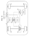
- FIG. 13 is a diagram illustrating another application example.
- a structure In the case of using a number of power storage elements, for example battery cells, for generating high output, for example, such a structure is employed that a plurality of power storage units is connected and a common control device is provided for the plurality of power storage units.
- the power storage unit is referred to as a power storage module as appropriate.
- a system including one or a plurality of power storage modules and a control device provided as a structure common among the modules is referred to as a power storage system as appropriate.
- the power storage system may be referred to as a string.
- a power storage module as an example of the power storage device is the unit obtained by combining a battery block and a module controller.
- the battery block is also referred to as a sub-module.
- the battery block is constructed by, for example, connecting eight cylindrical lithium ion secondary batteries in parallel.
- the power storage module is housed in an exterior case and within the exterior case of the power storage module, for example, 16 battery blocks are connected in series. Note that the number of battery blocks and the connection state can be changed as appropriate.
- the power storage module includes an exterior case.
- the exterior case is desirably formed of a material with high thermal conductivity and high radiation rate.
- the use of the material with the high conductivity and high radiation rate enables the exterior case to have the excellent heat release property. With the excellent heat release property, the temperature increase in the exterior case can be suppressed. Moreover, the opening portion of the exterior case can be minimized or omitted, whereby the high dust-proof and water-proof properties can be achieved.
- the exterior case for example, aluminum, aluminum alloy, copper, copper alloy, or the like can be used.
- a lithium ion secondary battery is used as an example of the secondary battery.
- the lithium ion secondary battery is, for example, the secondary battery including a positive electrode active material, and a carbon material such as graphite as a negative electrode active material.
- the positive electrode material is not particularly limited; preferably, a positive electrode active material having an olivine structure is contained.
- the lithium ion secondary battery is described as the example of the secondary battery; however, other secondary batteries than the lithium ion secondary battery can be applied to the embodiment of the present technology.
- the use of the lithium ion secondary battery under low temperature or high temperature deteriorates the performance.
- the lithium ion secondary battery is charged under a temperature of less than 0 degC.
- lithium ions from the positive electrode is absorbed in the negative electrode less easily and lithium metal is separated out on the surface of the negative electrode, whereby the electrode resistance is increased.
- the absorption of lithium ions is further interrupted.
- the interruption of the reaction in the electrode decreases the efficiency of the charging and discharging, resulting in the lower performance (capacitance, cycle lifetime, or the like) of the lithium ion secondary battery. For these reasons, under the low temperature, the charging is prohibited or the charging current is controlled to be small.
- the performance thereof may be deteriorated.
- the performance of the lithium ion secondary battery may be deteriorated.
- the temperature can be measured by, for example, a temperature detector such as a thermistor provided for the power storage module.
- the temperature information may be acquired through the network from, for example, an external device providing weather information.
- the lithium ion secondary battery when used as the secondary battery, it is desirable to know not just the charging and discharging time by large current under the high temperature but also the use circumstances of the power storage module in at least a low-temperature region and a high-temperature region among the regions based on temperature.
- FIG. 1 illustrates an example of the power storage system.
- a power storage system 1 denoted by a reference symbol 1
- N number of power storage modules MOD 1 to MODN are connected in series.
- the power storage module is referred to as MOD.
- the number of power storage modules to be connected and the connection state thereof can be changed as appropriate.
- the power storage modules MOD 1 to MODN are connected to an interface bus BS through an insulating portion IS.
- Each of the power storage modules MODs is provided with an insulating interface for connecting between the module controller and the interface bus BS. This insulating interface serves to insulate between the power storage module MOD and the interface bus BS.
- Each module controller is connected to the entire control device (hereinafter referred to as controller as appropriate) ICNT, and the controller ICNT performs management for the charging, discharging, deterioration suppression, or the like.
- the serial interface As the bus in the power storage module MOD and the interface bus BS that connects between the power storage modules MOD 1 to MODN and the controller ICNT, the serial interface is used.
- a System Management Bus (SM bus) or the like is used.
- SM bus System Management Bus
- I2C bus can be used. I2C bus is for the synchronous serial communication performing the communication through two signal lines of bidirectional SDA (serial data) and SCL (serial clock).
- the module controller of each power storage module MOD and the controller ICNT perform the communication.
- the controller ICNT receives the information on the internal state of each power storage module MOD, so that the charging process and the discharging process of each power storage module MOD are managed.
- the controller ICNT supplies the output of the serial connection of the N number of power storage modules MODs to the load.
- the power storage modules MODs are mutually connectable.
- FIG. 2 illustrates another example of the power storage system.
- N number of power storage modules MOD 1 to MODN are connected in series.
- Each of the power storage modules MOD 1 to MODN has an insulating interface for insulating between the power storage modules MODs.
- the module controller of each power storage module MOD communicates with the upper or lower power storage module MOD or with the external controller ICNT.
- the controller ICNT is connected to the lowest power storage module MOD 1 .
- the controller ICNT controls the entire power storage system. For example, the information on the internal state of each power storage module MOD is received by the controller ICNT and by supplying or blocking the charging current and the discharging current to each power storage module MOD, the charging and discharging of each power storage module MOD are controlled.
- a control signal from the controller ICNT is transmitted to the upper power storage module MOD through, for example, the lower power storage module MOD.
- FIG. 3 An example of the structure of the power storage module MOD is described with reference to FIG. 3 . Note that although the structure of the power storage module MOD 1 is used as an example, this structure similarly applies to the other power storage modules MODs.
- the power storage module MOD 1 includes, for example, a positive electrode terminal 4 , a negative electrode terminal 5 , a power storage unit, a module controller CTN 1 , an insulating unit ISC 1 , a communication unit COM 1 , a current detector 9 , a temperature detector 15 , a multiplexer (MUX) 16 , a pulse generator 17 , and a module balance control circuit MBC.
- a positive electrode terminal 4 a negative electrode terminal 5
- a power storage unit includes, for example, a positive electrode terminal 4 , a negative electrode terminal 5 , a power storage unit, a module controller CTN 1 , an insulating unit ISC 1 , a communication unit COM 1 , a current detector 9 , a temperature detector 15 , a multiplexer (MUX) 16 , a pulse generator 17 , and a module balance control circuit MBC.
- MUX multiplexer
- the power storage unit includes, for example, 16 battery blocks (battery blocks B 1 to B 16 ) connected in series. Each battery block is constructed by connecting eight cylindrical lithium ion secondary batteries in parallel; however, the present technology is not limited thereto.
- Each of the battery blocks B 1 to B 16 is connected to the module controller CTN 1 , and charging and discharging are controlled by the module controller CTN 1 . The charging and discharging are performed through the positive electrode terminal 4 and the negative electrode terminal 5 .
- one power storage module outputs about 51.2 V (16*3.2 V).
- the module controller CTN 1 includes, for example, an ADC (Analog to Digital Converter) 6 , a control unit 7 , and a multiplexer 8 .
- the module controller CTN 1 detects the voltage at opposite ends of the 16 battery blocks B 1 to B 16 connected in series and the voltage of each battery block.
- the multiplexer 8 sequentially outputs the voltage at opposite ends of the battery blocks B 1 to B 16 and the voltage of each battery block.
- the multiplexer 8 switches the channels in response to control signals from the control unit 7 to select one piece of analog voltage data from among n number of pieces of analog voltage data.
- the one piece of analog voltage data selected by the multiplexer 8 is supplied to the ADC 6 .
- the ADC 6 converts the analog data input to the module controller CTN 1 into digital data, and outputs the digital data to the control unit 7 .
- the ADC 6 converts the analog voltage data supplied from the multiplexer 8 into digital voltage data.
- the analog voltage data are converted into digital voltage data of 14 to 18 bits.
- the digital data generated by the ADC 6 are output to the communication unit COM 1 through the insulating unit ISC 1 by the control of the control unit 7 .
- 16 pieces of digital voltage data are time-divisionally multiplexed and output to the communication unit COM 1 .
- the control unit 7 includes, for example, a Central Processing Unit (CPU).
- the control unit 7 may include a plurality of CPUs.
- the control unit 7 manages the charging and discharging of the power storage unit. For example, upon the detection of the flow of excessive current at the discharging, the control unit 7 determines the state as the over-current discharging state and controls the switch (not shown) to an open state (state of blocking the current). On the other hand, upon the detection of excessive current in the charging or overcharging, the control unit 7 controls the switch (not shown) to an open state (state of blocking the current).
- the switch controlled to be on or off by the control unit 7 is connected to a power line between the module controller CTN 1 and the positive electrode terminal 4 or a power line between the module controller CTN 1 and the negative electrode terminal 5 .
- the control unit 7 sets the charging current and the discharging current to the power storage unit. For example, the control unit 7 sets the charging current and the discharging current in the regions set based on the temperature to appropriate values.
- the insulating unit ISC 1 has a function of insulating between the communication unit COM 1 and the module controller CTN 1 .
- the reference potential of the power source of the communication unit COM 1 and the reference potential of the power source of the module controller CTN 1 are separated and made independent.
- the insulating unit ISC 1 has the function of supplying the power source voltage to the module controller CTN 1 and the function as a transmission medium of the bidirectional communication.
- CAN Controller Area Network
- an electromagnetic induction type, a magnetic resonance type, a radio wave reception type, or the like can be used.
- a noncontact IC card technology is used.
- communication and power transmission are performed between a reader/writer and a card by the magnetic coupling between an antenna coil of the reader/writer and an antenna coil of the card.
- the communication is performed at a speed of 212 or 424 kbps by using a method in which the carrier wave with a frequency of 13.56 kHz is modulated by Amplitude Shift Keying (ASK).
- the insulating unit ISC 1 has the specification similar to the noncontact IC card. Moreover, for example, the insulating unit ISC 1 performs the communication and the power transmission between the antennas (coils) formed in the different layers of the multilayer printed board.
- the communication unit COM 1 includes, for example, a communication terminal 20 , a Micro Controller Unit MCU) 21 , a power source unit 22 , and a memory 23 .
- the communication unit COM 1 performs the communication with an external device to be connected through the communication terminal 20 .
- the communication terminal 20 communication between the power storage module MOD 1 and the controller ICNT or the other power storage modules MODs is performed.
- the control signal from the controller ICNT is input to the power storage module MOD 1 through the communication terminal 20 .
- the communication through the communication unit COM 1 may be either wired or wireless.
- the communication unit COM 1 performs the bidirectional communication.
- the data supplied from the module controller CTN 1 are input to the communication unit COM 1 through the insulating unit ISC 1 .
- the data supplied from the module controller CTN 1 include the digitized voltage data for each battery block, the digitized temperature data, the digitized current data, and the data acquired by the control of the control unit 7 , or the like.
- the data input to the communication unit COM 1 are output to, for example, the controller ICNT.
- the MCU 21 controls the communication between the power storage module MOD 1 and the controller ICNT.
- the MCU 21 may perform other controls than the control over the communication.
- the power source unit 22 supplies the power source voltage for operating, for example, the communication unit COM 1 .
- the power source unit 22 may be chargeable by the power from the power storage unit.
- the memory 23 includes, for example, a Read Only Memory (ROM) and a Random Access Memory (RAM).
- the ROM stores programs to be executed by the MCU 21 or the control unit 7 .
- the RAM is used as the work memory of the MCU 21 .
- the data supplied from the module controller CTN 1 , the data obtained by the control of the MCU 21 , and the data supplied from the controller ICNT are stored in the RAM temporarily.
- the RAM stores the use history (log) of the power storage module MOD 1 . For example, the RAM stores the charging time at a certain temperature, the discharging time at a certain temperature, and the time obtained by integrating these times.
- the current detector 9 detects the value of current flowing through the battery blocks B 1 to B 16 .
- the current detector 9 includes, for example, a current detection resistor 9 a and a current detection amplifier 9 b .
- the current detection resistor 9 a detects the analog current data representing the voltage value at the opposite ends of the current detection resistor 9 a .
- the analog current data are constantly detected either during the charging or the discharging, for example.
- the analog current data may be detected at a predetermined cycle.
- the detected analog current data are supplied to the current detection amplifier 9 b .
- the current detection amplifier 9 b amplifies the analog current data at a predetermined amplification ratio.
- the amplified analog current data are supplied to the ADC 6 of the module controller CTN 1 .
- the analog current data are converted into the digital current data.
- the digital current data are output from the module controller CNT 1 to the communication unit COM 1 .
- the temperature detector 15 includes a temperature detection element such as a thermistor.
- the temperature detector 15 includes one or a plurality of temperature detection elements.
- the temperature detection element is provided for each battery block so that the temperature of each battery block can be detected.
- the analog temperature data T representing the temperature of each of the battery blocks B 1 to B 16 detected by the temperature detector 15 are supplied to a multiplexer 16 .
- the analog temperature data T 1 representing the temperature of the battery block B 1 are supplied to the multiplexer 16 .
- the analog temperature data T 2 representing the temperature of the battery block B 2 are supplied to the multiplexer 16 .
- the analog temperature data T 3 to the analog temperature data T 16 respectively representing the temperatures of the battery block B 3 to the battery block B 16 are supplied to the multiplexer 16 .
- the multiplexer 16 selects one piece of analog temperature data T from among 16 pieces of analog temperature data T 1 to T 16 by switching the channel in response to a predetermined control signal.
- the one piece of analog temperature data T selected by the multiplexer 16 is supplied to the ADC 6 of the module controller CTN 1 .
- the analog temperature data T are converted into the digital temperature data T by the ADC 6 , and the converted digital temperature data T are output, for example, from the module controller CTN 1 to the communication unit COM 1 .
- the power storage module MOD of the embodiment of the present technology can perform the control for homogenizing the voltages of the battery blocks B 1 to B 16 , i.e., the cell balance control.
- the module balance control circuit MBC includes, for example, a flyback transformer TR 1 , a switch S 1 on the primary side of the flyback transformer TR 1 , and a switch S 01 on the secondary side of the flyback transformer TR 1 .
- the switches S 1 and S 01 are formed of, for example, Metal Oxide Semiconductor Field Effect Transistor (MOSFET), and each have a structure including a parasitic diode.
- MOSFET Metal Oxide Semiconductor Field Effect Transistor
- the cell balance control is executed by, for example, the control unit 7 .
- the cell balance control is described schematically. For example, when the discharge voltage of one of the plurality of battery blocks B 1 to B 16 reaches to the lower limit, the other battery blocks still have a capacity left. In the next charging, the other battery blocks having the capacity left reaches the charge upper-limit voltage sooner and therefore the fully-charged state cannot be obtained. For avoiding such unbalance, the Metal Oxide Semiconductor Field Effect Transistor (MOSFET) is turned on so that the battery block having the capacity left is forcibly discharged.
- MOSFET Metal Oxide Semiconductor Field Effect Transistor
- the type of the cell balance control is not limited to the passive type as described above and may be so-called active type or other various types.
- the pulse generator 17 generates control pulses in response to control signals from the control unit 7 .
- the pulse generator 17 outputs the control pulses whose pulse width is modulated.
- the control pulses for the switch S 1 is supplied from the pulse generator 17 to control the on/off of the switch S 1 .
- the control pulse for the switch S 01 on the secondary side of the flyback transformer TR 1 is supplied from the MCU 21 in the communication unit COM 1 to control the on/off of the switch S 01 .
- the power storage module is not limited to the described example but may have another structure added or the structure eliminated as appropriate.
- the controller ICNT is capable of communication with a plurality of power storage modules MODs and communication with a device connected to the network NTW through the network NTW.
- the network NTW is, for example, the Internet.
- the device connected to the network NTW is, for example, a maintenance device for maintaining the power storage system.
- FIG. 4 illustrates an example of the structure of the controller ICNT.
- the controller ICNT includes, for example, a control unit 30 , a first communication unit 31 , a second communication unit 32 , a display unit 33 , and a storage unit 34 .
- the first communication unit 31 and the second communication unit 32 are abbreviated as the communication unit 31 and the communication unit 32 , respectively.
- the control unit 30 includes, for example, a CPU, and controls each unit of the controller ICNT.
- the communication unit 31 is to communicate with each power storage module MOD.
- the communication unit 32 is to communicate with the device connected to the network NTW based on a predetermined communication method.
- the display unit 33 includes a driver and a display panel.
- the display unit 33 displays, for example, the operation status of the power storage system.
- the display in regard to the operation status of the power storage system includes the display notifying that the power storage system is in normal operation, the warning notifying that the abnormality occurs in the power storage system, the display suggesting the maintenance, the display notifying that a predetermined power storage system is forcibly stopped for safety, or the like. Note that the user may be notified of the operation status of the power storage system by the lighting of a Light Emitting Diode (LED) or sound or using these with the display.
- LED Light Emitting Diode
- the storage unit 34 includes, for example, a ROM and a RAM.
- the ROM stores programs to be executed by the control unit 30 .
- the RAM is used as the work memory when the control unit 30 executes the process.
- the RAM stores the data supplied from the power storage module MOD or the data supplied through the network NTW temporarily.
- the horizontal axis represents the temperature (degC.) and the vertical axis represents the charging/discharging current or the integral time coefficient corresponding to an example of the weighting factor.
- C is used as the unit of the magnitude of the charging/discharging current.
- 1 C is the value of current at which the theoretical capacity is fully discharged (or charged) in an hour.
- the graph L 1 of the solid line represents the magnitude of the charging current.
- the magnitude of the charging current is set by the control unit 7 of the module controller CTN 1 in response to the control by the controller ICNT.
- the charging current is set to, for example, 0.2 C (charging current limited).
- the charging current is set to, for example, 0.5 C (charging current limited).
- the charging current is set to, for example, 1.0 C (normal charging and discharging).
- the temperature is higher than 50 degC., the charging is prohibited (charging prohibited).
- the graph L 2 of the alternate long and short dash line represents the magnitude of the discharging current.
- the magnitude of the discharging current is set by the control unit 7 of the module controller CTN 1 in response to the control by the controller ICNT.
- the discharging of the power storage module MOD is set to 1.0 C.
- the discharging current is set to, for example, 2.0 C.
- the discharging is prohibited.
- the control unit 7 serves as the evaluation value acquisition unit that acquires the evaluation value based on the use circumstances (operation status) of the power storage unit of the power storage module MOD.
- the control unit 7 acquires at least the evaluation value in the high-temperature region and the evaluation value in the low-temperature region among the plurality of regions set based on temperature.
- the high temperature region and the low-temperature region are the regions where the performance of the power storage unit may deteriorate when the power storage module MOD is used in those regions.
- Region 1 temperature measured by the temperature detector 15 is lower than 0 degC.
- Region 2 temperature measured by the temperature detector 15 is higher than 0 degC. and lower than 10 degC.
- Region 3 temperature measured by the temperature detector 15 is higher than 10 degC. and lower than 45 degC.
- Region 4 temperature measured by the temperature detector 15 is higher than 45 degC.
- At least one of Region 1 and Region 2 corresponds to an example of the low-temperature region and Region 4 corresponds to an example of the high-temperature region.
- the control unit 7 acquires the evaluation value by using the integral time coefficient as an example of the weighting factor.
- the integral time coefficient is set for each target region from which the evaluation value is acquired, for example.
- the integral time coefficient of Region 1 is 1.0
- the integral time coefficient of Region 2 is 0.3
- the integral time coefficient of Region 3 is 0.1
- the integral time coefficient of Region 4 is 1.0. Since the performance of the lithium ion secondary battery may deteriorate by the use under low temperature or high temperature, the integral time coefficient is set to be larger as the temperature becomes lower or higher in the embodiment of the present technology.
- control unit 7 acquires each of the evaluation values of Region 1, Region 2, and Region 4.
- the evaluation value in Region 1 is obtained by Formula (1) below, for example. (Integral time obtained by integrating the time for which the power storage unit is charged in the temperature range of lower than 0degC.)*integral time coefficient (1.0) (1)
- the evaluation value in Region 2 is obtained by Formula (2) below, for example. (Integral time obtained by integrating the time for which the power storage unit is charged in the temperature range of higher than 0degC. and lower than 10degC.)*integral time coefficient (0.3) (2)
- the evaluation value in Region 4 is obtained by Formula (3) below, for example. (Integral time obtained by integrating the time for which the power storage module MOD is used in the temperature range of higher than 45degC.)*integral time coefficient (1.0) (3)
- the time for which the power storage module MOD is used in Formula (3) includes, for example, the time for which the power storage module MOD is charged, the time for which the power storage module MOD is discharged, and the time for which the power storage module MOD is left without being charged or discharged.
- the time corresponds to the time for which the power storage module MOD is exposed to the environment at a temperature of higher than 45 degC.
- the integral time in each formula can be obtained by referring to the use history of the power storage module MOD 1 stored in the memory 23 .
- the control unit 7 acquires the temperature based on the temperature information supplied from the temperature detector 15 , accumulates the charging time, or the like at each temperature and stores the results in the memory 23 .
- the evaluation value in each region is obtained using Formulae (1) to (3) at an appropriate timing and the value based on the evaluation value is calculated.
- the value based on the evaluation value may be an individual evaluation value and may be the value obtained by performing a predetermined calculation on each evaluation value.
- the value obtaining by totaling the evaluation value from Formula (1), the evaluation value from Formula (2), and the evaluation value from Formula (3) corresponds to the value based on the evaluation value.
- the total evaluation value is stored in the memory 23 as the accumulative time information representing the deterioration degree of the power storage module MOD. In the case where the total evaluation value is acquired newly, the total evaluation value is updated and the updated total evaluation value is stored in the memory 23 .
- the control unit 7 executes the control in response to the total evaluation value. For example, the control unit 7 outputs the total evaluation value to the communication unit COM 1 in response to the request from the controller ICNT. By the control from the MCU 21 in the communication unit COM 1 , the total evaluation value is transmitted from the communication unit COM 1 to the controller ICNT. Note that the total evaluation value may be correlated with the identifier (Identifier (ID)) for identifying the power storage module MOD.
- ID identifier
- controller ICNT an example of the operation of the controller ICNT is described.
- the operation in regard to the embodiment of the present technology is described; however, the operation of the controller ICNT is not limited to the described one but may be the well-known one.
- the controller ICNT receives in the communication unit 31 , the data representing the total evaluation value transmitted from the power storage module MOD.
- the data representing the total evaluation value are supplied from the communication unit 31 to the control unit 30 .
- the control unit 30 appropriately acquires the total evaluation value by, for example, demodulating the data representing the total evaluation value.
- the control unit 30 compares the total evaluation value with a threshold.
- a threshold for example, three thresholds are set.
- the three thresholds for example, 7000 hours, 9000 hours, and 10000 hours are set.
- the control unit 30 outputs the signal for warning (hereinafter referred to as a warning signal as appropriate) to the display unit 33 when the total evaluation value exceeds 7000 hours.
- a warning signal As appropriate
- the display unit 33 displays the warning. Note that when the total evaluation value is less than 7000 hours, it is determined that the power storage system is normal (the deterioration is not progressed to the level).
- the control unit 30 When the total evaluation value exceeds 9000 hours, the control unit 30 outputs the signal for notifying beforehand the stop of the power storage system (hereinafter referred to as a stop notification signal as appropriate) on the display unit 33 . In response to the stop notification signal, the display unit 33 displays the information notifying that the power storage system stops in the near future.
- the control unit 30 When the total evaluation value exceeds 9000 hours, the control unit 30 outputs a predetermined signal.
- the predetermined signal corresponds to, for example, a signal indicating that the power storage system needs to be maintained (the signal is referred to as a maintenance inspection calling signal as appropriate).
- the maintenance inspection calling signal output from the control unit 30 is transmitted to the network NTW through the communication unit 32 . Then, the maintenance inspection calling signal is transmitted to the maintenance device connected to the network NTW.
- the ID for identifying the power storage module MOD may be added to the predetermined signal. This enables the power storage module MOD, which is identified by the ID, to be thoroughly inspected in the maintenance of the power storage system. Note that the example of the maintenance system will be specifically described in the application example below.
- the control unit 30 When the total evaluation value exceeds 10000 hours, the control unit 30 outputs the signal for stopping the operation of the power storage system (hereinafter referred to as a stop signal as appropriate). In response to the stop signal, the power storage system stops to operate and the charging or discharging by the power storage system is prohibited.
- the display unit 33 of the controller ICNT may display the information representing that the operation of the power storage system is stopped forcibly.
- FIG. 6 is a flowchart illustrating an example of the flow of the process in the first embodiment.
- the power storage module MOD is activated by turning on the switch provided for the controller ICNT.
- the voltage (module voltage) VM of the power storage module MOD is acquired. Whether the module voltage VM is in a certain range (Vmin to Vmax) or not is determined (Step ST 101 ). Specifically, whether the minimum voltage of the plurality of batter blocks is greater than Vmin is determined and whether the maximum voltage of the plurality of battery blocks is less than Vmax or not is determined.
- Step ST 102 When the module voltage VM is out of the certain range (Vmin to Vmax), a safety operation process is performed (Step ST 102 ).
- the power storage unit When the module voltage VM is out of the certain range (Vmin to Vmax), the power storage unit is in the overcharged or overdischarged state.
- the safety operation process in the occurrence of the overcharging, the power storage unit is forcibly discharged and in the occurrence of the overdischarging, the preliminary charging by a preliminary charging circuit (not shown) is performed.
- the module voltage VM stays within the certain range (Vmin to Vmax).
- each circuit in the power storage module MOD is activated and the initialization (initialize) process is executed as necessary (Step ST 103 ).
- the module controller CTN 1 After the activation of the circuit, the module controller CTN 1 acquires the voltage of the battery block. Moreover, the module controller CTN 1 acquires the temperature information from the temperature detector 15 (Step ST 104 ). In accordance with the temperature indicated by the temperature information, the charging current is set.
- Step ST 105 When the temperature T is lower than ⁇ 10 degC., the control is made to prohibit the charging.
- the use history (log) in this temperature range is stored in the memory 23 (Step ST 105 , Step ST 106 , Step ST 107 ).
- the control is made to set the charging current to 0.1 C.
- the use history in this temperature range is stored in the memory 23 (Step ST 108 , Step ST 109 , Step ST 110 ).
- Step ST 111 When the temperature T is higher than 0 degC. and lower than 10 degC., the control is made to set the charging current to 0.5 C.
- the use history in this temperature range is stored in the memory 23 (Step ST 111 , Step ST 112 , Step ST 113 ).
- Step ST 114 When the temperature T is higher than 10 degC. and lower than 50 degC., normal charging is performed. For example, the control is made to set the charging current to 1.0 C. Note that the charging current may be changed for the quick charging, or the like.
- the use history in this temperature range is stored in the memory 23 (Step ST 114 , Step ST 115 , Step ST 116 ).
- the control is made to prohibit the charging.
- the use history in this temperature range is stored in the memory 23 (Step ST 117 , Step ST 118 , Step ST 119 ).
- Step ST 120 the control unit 7 executes the process of calculating the evaluation value and the value based on the evaluation value (Step ST 120 ).
- the evaluation value is, for example, calculated based on Formulae (1) to (3) above. Note that the timing of the process of Step ST 120 can be set as appropriate.
- the total evaluation value is output from the control unit 7 to the communication unit COM 1 . Then, the total evaluation value is output to the controller ICNT through the communication unit COM 1 (Step ST 121 ).
- the total evaluation value transmitted from the power storage module MOD is received by the controller ICNT. Then, the total evaluation value is acquired by the control unit 30 of the controller ICNT. As described above, the control unit 30 compares the total evaluation value with the threshold and executes the process in accordance with the comparison result (Step ST 122 ).
- FIG. 6 illustrates the setting of the charging current only
- the discharging current is set in accordance with the temperature as appropriate. For example, when the discharging is performed in the temperature range of lower than ⁇ 20 degC., the discharging current is set to, for example, 1.0 C. When the discharging is performed in the temperature range of ⁇ 20 degC. to 60 degC., the discharging current is set to, for example, 2.0 C. When the temperature is higher than 60 degC., the discharging is prohibited.
- the use history such as the discharging time at each temperature is stored in the memory 23 .
- the first embodiment of the present technology it is possible to accurately know the deterioration in performance of the power storage unit of the power storage module MOD.
- the user can be notified with the warning, or the like.
- the operation of the power storage system is stopped so that the power storage system can be used safely.
- the aforementioned first embodiment can be modified as below, for example.
- the temperature detector 15 is constructed by a plurality of temperature detection elements, for example, the average value or the intermediate value of the temperatures detected by the plurality of temperature detection elements is used. Whether the region is either Region 1 or Region 2 may be determined based on the minimum temperature of the temperatures detected by the plurality of temperature detection elements. Moreover, whether the region is either Region 3 or Region 4 may be determined based on the maximum temperature of the temperatures detected by the plurality of temperature detection elements.
- the controller ICNT executes the process based on the total evaluation value; however, the control unit 7 of the power storage module MOD may execute the process based on the total evaluation value. For example, the control unit 7 may compare the total evaluation value and the threshold and output the signal in accordance with the comparison result to the controller ICNT.
- the evaluation values of the regions other than Region 3 are obtained; however, the evaluation values of the entire regions may be acquired assuming that the integral time coefficient of Region 3 is 0.
- the use of the power storage module MOD in Region 3 does not drastically promote the deterioration of the power storage module MOD; thus, the integral time coefficient is set to 0 or decreased (for example, to about 0.1), thereby preventing the total evaluation value from becoming large.
- the structure in which the charging is possible in the temperature range of lower than ⁇ 20 degC. may also be employed.
- the charging current is set smaller, and the integral time coefficient is set larger than 1.0.
- control unit 7 may be executed entirely or partly by the MCU 21 .
- a dedicated microcomputer for executing the above processes may be provided.
- the use condition of the power storage unit is changed when the total evaluation value exceeds the threshold. Moreover, the evaluation value in each region is acquired by changing the integral time coefficient in the region based on the temperature.
- the control unit 30 of the controller ICNT determines that the total evaluation value is greater than 7000 hours
- the warning is displayed.
- the control unit 30 of the controller ICNT determines that the total evaluation value is greater than 10000 hours
- the operation of the power storage system is forcibly stopped.
- the stop of the operation of the power storage system may cause the inconvenience in the place having no commercial power source because the power cannot be used.
- the stop of the power supply can endanger the life of patients.
- the stored power of the power storage system cannot be used so that the user feels inconvenience.
- the use condition of the power storage unit is changed by restricting the charging current and the discharging current.
- the control is made to restrict the charging current and the discharging current to approximately a half.
- the integral time coefficient in the region based on the temperature is reset and the evaluation value is acquired.
- the region based on the temperature may be reset. Note that as the process performed before the total evaluation value exceeds 7000 hours, the process in the first embodiment described above can be applied.
- FIG. 7 illustrates an example of the charging current, the discharging current, and the integral time coefficient that are reset when the total evaluation value exceeds 7000 hours.
- the graph L 10 of the solid line in FIG. 7 represents the magnitude of the charging current.
- the magnitude of the charging current is restricted by the control unit 7 of the module controller CTN 1 in accordance with the control by the controller ICNT, for example.
- the charging of the power storage module MOD in the temperature range of less than ⁇ 10 degC. is prohibited.
- the charging current in the temperature range of ⁇ 10 degC. to 0 degC. is changed from, for example, 0.2 C to 0.1 C.
- the charging current in the temperature range of 0 degC. to 10 degC. is changed from, for example, 0.5 C to 0.25 C.
- the charging current in the temperature range of 10 degC. to 50 degC. is changed from, for example, 1.0 C to 0.5 C.
- the graph L 20 of the alternate long and short dash line in FIG. 7 represents the magnitude of the discharging current.
- the magnitude of the discharging current is restricted by the control unit 7 of the module controller CTN 1 in accordance with the control by the controller ICNT, for example.
- the discharging current in the temperature range of less than ⁇ 20 degC. is changed from 1.0 C to 0.5 C.
- the discharging current in the temperature range of ⁇ 20 degC. to 60 degC. is changed from 2.0 C to 1.0 C.
- the discharging of the power storage module MOD in the temperature range of higher than 60 degC. is prohibited.
- regions as below are set.
- Region 1 the temperature measured by the temperature detector 15 is in the range of lower than 0 degC.
- Region 2 the temperature measured by the temperature detector 15 is in the range of higher than 0 degC. and lower than 10 degC.
- Region 3 the temperature measured by the temperature detector 15 is in the range of higher than 10 degC. and lower than 45 degC.
- Region 4 the temperature measured by the temperature detector 15 is in the range of higher than 45 degC.
- the integral time coefficient in each region is reset. As indicated by the dotted line L 30 in FIG. 7 , 0.5 is set as the integral time coefficient in Region 1, 0.15 is set as the integral time coefficient in Region 2, 0.05 is set as the integral time coefficient in Region 3, and 0.5 is set as the integral time coefficient in Region 4.
- the control unit 7 acquires at least the evaluation value in the low-temperature region and the evaluation value in the high-temperature region. In this example, the control unit 7 acquires the evaluation values in all the regions including Region 3.
- the evaluation value in Region 1 is obtained by, for example, Formula (4) below: (Integral time obtained by integrating the time for which the power storage unit is charged in the temperature range of lower than 0degC.)*integral time coefficient (0.5) (4)
- the evaluation value in Region 2 is obtained by, for example, Formula (5) below: (Integral time obtained by integrating the time for which the power storage unit is charged in the temperature range of higher than 0degC. and lower than 10degC.)*integral time coefficient (0.15) (5)
- the evaluation value in Region 3 is obtained by, for example, Formula (6) below: (Integral time obtained by integrating the time for which the power storage module MOD is used in the temperature range of higher than 10degC. and lower than 45degC.)*integral time coefficient (0.05) (6)
- the evaluation value in Region 4 is obtained by, for example, Formula (7) below: (Integral time obtained by integrating the time for which the power storage module MOD is used in the temperature range of higher than 45degC.)*integral time coefficient (0.5) (7)
- the control unit 7 acquires the temperature based on the temperature information supplied from the temperature detector 15 , and stores the use history such as the charging time at each temperature in the memory 23 . Then, with reference to the use history stored in the memory 23 , the control unit 7 obtains the evaluation value in each region by using the above Formulae (4) to (7) at appropriate timing, and calculates the value based on the evaluation value.
- the value based on the evaluation value refers to the value obtained by adding 7000 hours to the value obtained by summing up the evaluation value from Formula (4), the evaluation value from Formula (5), the evaluation value from Formula (6), and the evaluation value from Formula (7).
- This value (total evaluation value) is stored in the memory 23 as the accumulative time information representing the deterioration degree of the power storage module MOD. Upon the acquisition of the new total evaluation value, the total evaluation value is updated total evaluation value is stored in the memory 23 .
- the control unit 7 executes the control in accordance with the total evaluation value. For example, in response to the request from the controller ICNT, the control unit 7 outputs the total evaluation value to the communication unit COM 1 . By the control of the MCU 21 in the communication unit COM 1 , the total evaluation value is transmitted to the controller ICNT through the communication terminal 20 . Note that the total evaluation value may be output while being associated with the ID for identifying the power storage module MOD.
- the controller ICNT receives in the communication unit 31 , the data representing the total evaluation value transmitted from the power storage module MOD.
- the data representing the total evaluation value are supplied from the communication unit 31 to the control unit 30 .
- the control unit 30 acquires the total evaluation value by performing a demodulation process or the like on the data representing the total evaluation value as appropriate.
- the control unit 30 compares the total evaluation value with the threshold.
- the control unit 30 outputs the stop notification signal when the total evaluation value exceeds 9000 hours.
- the control unit 30 may output the maintenance inspection calling signal.
- the control unit 30 outputs the stop signal.
- the operation of the power storage system is stopped and the charging and discharging by the power storage system are prohibited.
- the warning is displayed and the setting of the charging and discharging of the power storage module MOD is changed to the method causing less deterioration. Since the setting of the charging and discharging is changed to the method causing less deterioration of the power storage unit, the integral time coefficient is reset to be smaller. Therefore, it is possible to delay the time where the total evaluation value reaches the threshold at which the power storage system is stopped (for example, 10000 hours). By performing the maintenance inspection of the power storage system before the total evaluation value reaches the threshold at which the power storage system is stopped (for example, 10000 hours), the stop of the power storage system can be prevented. Thus, the inconvenience caused by the stop of the power storage system can be avoided.
- the threshold for example, 7000 hours
- the charging current and the discharging current are restricted as the use condition of the power storage unit.
- the full charge voltage may be changed instead.
- the setting of the full charge voltage is performed by the control unit 7 of the module controller CTN 1 in accordance with the control by the controller ICNT.
- the full charge voltage is set as below before the total evaluation value exceeds 7000 hours.
- the full charge voltage is set to 4.10 V.
- the full charge voltage is set to 4.15 V. In the temperature range of 10 degC. to 45 degC., the full charge voltage is set to 4.20 V.
- the full charge voltage is set as below when the total evaluation value exceeds 7000 hours.
- the full charge voltage is set to 4.00 V.
- the full charge voltage is set to 4.05 V.
- the full charge voltage is set to 4.20 V.
- control may be performed to decrease the full charge voltage.
- the structure of the power storage module MOD and the controller ICNT in the third embodiment is similar to that of the first embodiment, for example.
- the components described in the first and second embodiments can apply to the third embodiment unless otherwise stated.
- the controller acquires the total evaluation value from each power storage module.
- the controller acquires the value based on the evaluation value (for example, total evaluation value) from only a particular power storage module (hereinafter referred to as a reference power storage module as appropriate) among a plurality of power storage modules. Based on the total evaluation value acquired by the controller, the deterioration degree of the power storage system is determined.
- the controller ICNT acquires the total evaluation vale in one reference power storage module MOD out of 16 power storage modules MODs.
- the controller ICNT determines whether the acquired evaluation value is greater than the threshold (for example, 7000 hours, 9000 hours and 10000 hours). Based on the result of determination, the warning or the like is displayed.
- the threshold for example, 7000 hours, 9000 hours and 10000 hours.
- the warning or the like is displayed.
- the total evaluation value is greater than a predetermined threshold, for example, all the power storage modules MODs included in the power storage system are subjected to the maintenance inspection, for example. Note that as the process of comparing the total evaluation value and the threshold or the process performed based on the comparison result, the process described in the first embodiment can be applied.
- the load of communication between the controller ICNT and the power storage module MOD can be reduced by which the controller ICNT acquires the total evaluation value only from the reference power storage module.
- the number of reference power storage modules may be more than one.
- the reference power storage module may be set in accordance with the temperature distribution.
- FIG. 8 illustrates an example of arrangement of the power storage system.
- the power storage modules are stacked sequentially from the power storage module MOD 1 , and the controller ICNT is disposed in the uppermost stage.
- the controller ICNT and each power storage module are connected through a positive power line, a negative power line, and a communication line.
- the controller ICNT and each power storage module are supported by a rack with a predetermined shape (not shown).
- the controller ICNT can specify the position of each power storage module by performing the initial communication with each power storage module, for example, and sets the power storage module from which the total evaluation value is acquired.
- the temperature of the power storage module MOD 16 positioned right below the controller ICNT tends to be high. In other words, the deterioration of the power storage module MOD 16 may progress more quickly than the other power storage modules MODs.
- the temperature of the power storage module MOD in the lowest stage apart from the controller ICNT tends to be low.
- the deterioration of the power storage module MOD 1 may progress more quickly than the other power storage modules MODs.
- the power storage module MOD 1 and the power storage module MOD 16 which are considered to deteriorate easily from the temperature distribution, are selected as the reference power storage modules.
- the controller ICNT acquires the total evaluation values of the power storage module MOD 1 and the power storage module MOD 16 .
- the controller ICNT compares the total evaluation values and the threshold. When at least one total evaluation value exceeds the threshold (for example, 7000 hours), the warning is displayed.
- the process described in the first embodiment can be applied.
- any of the power storage module MOD 1 and the power storage module MOD 16 may be maintained, or both power storage modules may be maintained. Moreover, other power storage modules MODs such as the power storage module MOD 2 may be maintained additionally.
- the deterioration of the power storage module MOD 1 and the power storage module MOD 16 is more severe than that of the power storage module MOD 2 and the like. Therefore, the deterioration of at least one of the power storage module MOD 1 and the power storage module MOD 16 may be determined and the other power storage modules MODs may be maintained based on that result.
- the controller ICNT and at least one of the power storage module MOD 1 and the power storage module MOD 16 may communicate with each other; thus, the communication load can be reduced to simplify the process.
- the controller ICNT may acquire the evaluation value in the low-temperature region (for example, Region 1 and Region 2) from the power storage module MOD 1 . Moreover, the evaluation value in the high-temperature region (for example, Region 3) may be acquired from the power storage module MOD 16 . The controller ICNT may calculate the total evaluation value from the two evaluation values obtained, and compare the total evaluation value and the threshold.
- a dedicated temperature detection element may be provided.
- the temperature detection element may be provided on the surface of the power storage module MOD 16 or in the vicinity of the center of the inside (for example the vicinity of the module balance control circuit MBC), which is considered to have the highest temperature, and in the vicinity of the side surface of the power storage module MOD 1 , which is considered to have the lowest temperature. It is not necessary to provide the temperature detection element in the other power storage modules MODs, and the correct temperature can be measured by a minimum number of temperature detection elements.
- the temperature detection element may be attached to the rack that supports the power storage system.
- FIG. 9 illustrates another example of the arrangement of the power storage system.
- Uninterruptible Power Supply (UPS) is disposed in the lowest stage, and the power storage modules (MOD 1 to MOD 14 ) are sequentially stacked on the UPS, and the controller ICNT is disposed in the uppermost stage.
- the controller ICNT, UPS, and each power storage module are connected through a positive power line, a negative power line, and a communication line.
- the controller ICNT, each power storage module, and UPS are supported by the rack (not shown).
- UPS has, for example, a power storage unit including a lead acid battery or the like, and an inverter device (these are not shown).
- the power storage module MOD 1 located closest to UPS tends to have the high temperature.
- the vicinity of the side surface of the case of the power storage module MOD 7 located far from the heat generator (UPS and controller ICNT) tends to have the low temperature.
- the power storage module MOD 1 and the power storage module MOD 7 are selected as the reference power storage modules.
- the controller ICNT acquires the total evaluation values of the power storage module MOD 1 and the power storage module MOD 7 .
- the controller ICNT compares each total evaluation value and the threshold. When at least one total evaluation value is greater than the threshold (for example, 7000 hours), the warning is displayed.
- the process described in the first embodiment can be applied.
- any of the power storage module MOD 1 and the power storage module MOD 7 may be maintained, or both power storage modules may be maintained. Further, other power storage modules MODs such as the power storage module MOD 2 may be maintained additionally.
- the deterioration of the power storage module MOD 1 and the power storage module MOD 7 is more severe than that of the power storage module MOD 2 and the like. Therefore, the deterioration of at least one of the power storage module MOD 1 and the power storage module MOD 7 may be determined and the other power storage modules MODs may be maintained based on that result.
- the controller ICNT and at least one of the power storage module MOD 1 and the power storage module MOD 7 may communicate with each other; thus, the communication load can be reduced to simplify the process.
- the controller ICNT may acquire the evaluation value in the low-temperature region (for example, Region 1 and Region 2) from the power storage module MOD 7 . Moreover, the evaluation value in the high-temperature region (for example, Region 3) may be acquired from the power storage module MOD 1 . The controller ICNT may calculate the total evaluation value from the two evaluation values obtained, and compare the total evaluation value and the threshold.
- a dedicated temperature detection element may be provided. It is preferable that the temperature detection element is provided directly to the battery of the power storage unit, or provided at an appropriate position in the vicinity of the center and/or the peripheral part of the batteries in the exterior of the power storage unit.
- the temperature detection element may be provided on the surface of the power storage module MOD 1 or in the vicinity of the center of the inside (for example the vicinity of the module balance control circuit MBC), which is considered to have the highest temperature, and in the vicinity of the side surface of the power storage module MOD 7 , which is considered to have the lowest temperature.
- the temperature detection element may be attached to the rack that supports the power storage system. The correct temperature can be measured by a minimum number of temperature detection elements by employing the above structure.
- Application Example 1 is the example in which the present technology is applied to a maintenance system for maintaining a power storage system.
- FIG. 10 illustrates the summary of a maintenance system 40 in Application Example 1.
- one or a plurality of power storage modules MODs is connected to the controller ICNT.
- the controller ICNT is connected to a maintenance device 50 through the network NTW.
- the maintenance device 50 is installed in such as companies that are engaged in maintenance and management of power storage systems.
- As the network NTW a public line such as the Internet can be used.
- FIG. 11 illustrates an example of the structure of the maintenance device 50 .
- the maintenance device 50 includes, for example, a control unit 51 , a communication unit 52 , a storage unit 53 , a display unit 54 , and a maintenance database (DB) 55 .
- DB maintenance database
- the control unit 51 includes, for example, a CPU, and controls each unit of the maintenance device 50 .
- the communication unit 52 communicates with the controller ICNT in the power storage system.
- the communication unit 52 receives signals transmitted from the controller ICNT.
- the communication unit 52 may communicate with another maintenance device (for example, maintenance device that geographically manages the power storage system that needs to be maintained) or a portable terminal of an operator who is in charge of maintaining the power storage system (hereinafter referred to as a maintenance operator as appropriate).
- the storage unit 53 includes, for example, a ROM and a RAM.
- the ROM stores programs to be executed by the control unit 51 .
- the RAM is used as the work memory when the control unit 51 executes the process or used as a region storing the data temporarily.
- the display unit 54 includes a driver and a display panel.
- the display unit 54 displays various pieces of information including information in regard to the maintenance of the power storage system.
- the maintenance database 55 is a high-capacity recording device in which the pieces of information in regard to the maintenance of the power storage system are accumulated. For example, the history regarding the maintenance in units of power storage systems and power storage modules is accumulated in the maintenance database 55 . Moreover, the location of the power storage system and the contact address of the users are accumulated in the maintenance database 55 while being associated with the user information.
- the maintenance database 55 may be a server device (so-called cloud computer) connected to the network NTW.
- the controller ICNT transmits the maintenance inspection calling signal when the total evaluation value acquired from the power storage system is greater than a certain threshold (for example, 9000 hours).
- a certain threshold for example, 9000 hours.
- the display unit 33 of the controller ICNT may display the message indicating that the maintenance request is currently made.
- the maintenance inspection calling signal is received by the communication unit 52 of the maintenance device 50 through the network NTW.
- the maintenance inspection calling signal includes the user information of the power storage system, for example.
- the maintenance inspection calling signal received by the communication unit 52 is supplied to the control unit 51 .
- the control unit 51 specifies the power storage system that needs the maintenance inspection with reference to the user information included in the maintenance inspection calling signal and the information accumulated in the maintenance database 55 .
- the control unit 51 executes the process in regard to the maintenance of the power storage system. For example, the control unit 51 sets the optimum time for exchanging the power storage module in the power storage system.
- the control unit 51 transmits the notification signal to the maintenance operator upon the reception of the maintenance inspection calling signal or at the set exchange time, with the use of the communication unit 52 .
- the information based on the user information or the like may be displayed on the display unit 54 .
- the notification signal transmitted from the maintenance device 50 is received by, for example, the portable terminal owned by the maintenance operator.
- the maintenance operator having confirmed the notification goes to the place where the power storage system is installed, and performs the following work, for example.
- the power storage module MOD to be exchanged may be all the power storage modules MODs or just deteriorated power storage modules MODs of the power storage system.
- Application Example 1 when the maintenance of the power storage system has become necessary, the maintenance device is automatically notified; therefore, the user does not need to perform the maintenance in regard to the important matter. As a result, the operation of the power storage system can be continued. Further, the maintenance can be performed as planned at the optimum timing in accordance with the use circumstances of the power storage system; thus, the cost of the maintenance can be reduced. Although it is difficult for a user to notice the deterioration in the use of the power storage system, Application Example 1 makes it possible to correctly detect the deterioration of the power storage system and manage the power storage system optimally.
- the third embodiment can be modified as below.
- the notification may be transmitted from the controller ICNT to the maintenance device.
- a label on which the contact address of the service center is written may be attached at a predetermined position of the power storage system. Separate from the aforementioned maintenance, the user can contact the address on the label voluntarily.
- the maintenance inspection calling signal may be transmitted from the controller ICNT to the maintenance device 50 when the warning is displayed.
- the controller ICNT may transmit the maintenance inspection calling signal when the total evaluation value is greater than 7000 hours.
- a power accumulation device 100 for a house 101 the electric power is supplied from a concentrated power system 102 such as a thermal power plant 102 a , an atomic power plant 102 b , or a hydroelectric power plant 102 c through a power network 109 , an information network 112 , a smart meter 107 , a power hub 108 , or the like to the power storage device 103 .
- the electric power is supplied to the power storage device 103 from an independent power source such as an in-house power generation device 104 .
- the electric power supplied to the power storage device 103 is accumulated. With the use of the power storage device 103 , the electric power to be consumed in the house 101 is supplied.
- the similar power accumulation device can be used not just in the house 101 but also in the building.
- the house 101 is provided with a control device 110 that controls each device of the in-house power generation device 104 , a power consumption device 105 , the power storage device 103 , and the like, the smart meter 107 , and a sensor 111 that acquires various pieces of information.
- the devices are connected by the power network 109 and the information network 112 .
- As the in-house power generation device 104 a solar cell, a fuel cell, and the like are used and the generated power is supplied to the power consumption device 105 and/or the power storage device 103 .
- the power consumption device 105 corresponds to a refrigerator 105 a , an air conditioner 105 b , a television receiver 105 c , a bathroom 105 d , and the like.
- an electric vehicle 106 is also included in the power consumption device 105 .
- the electric vehicle 106 corresponds to an electric car 106 a , a hybrid car 106 b , and an electric bike 106 c.
- the aforementioned power storage system can be used.
- the power storage device 103 can be installed either inside or outside the house. In either case, the state (deterioration degree) of the power storage device 103 can be correctly known by applying the present technology.
- the smart meter 107 has the function of measuring the consumption amount of the commercial power and transmitting the measured amount to the power company.
- the power network 109 any of or a plurality of DC power supply, AC power supply, and noncontact power supply may be used.
- the various sensors 111 for example, a motion sensor, an illuminance sensor, an object detection sensor, a consumption power sensor, a vibration sensor, a contact sensor, a temperature sensor, an infrared ray sensor, or the like can be used.
- the information acquired by the sensor 111 is transmitted to the control device 110 .
- the control device 110 can transmit the information in regard to the house 101 to the power company on the outside through the Internet.
- the power hub 108 By the power hub 108 , the branching of the power line or the conversion between DC and AD is performed.
- a method of using the communication interface such as Universal Asynchronous Receiver-Transmitter (UART: asynchronous serial communication transmission/reception circuit), or a method of using a sensor network based on the wireless communication specification such as Bluetooth (registered trademark), ZigBee (registered trademark), or Wi-Fi (registered trademark) is given.
- Bluetooth method is applied to the multimedia communication and one-to-many communication is possible.
- ZigBee uses the Institute of Electrical and Electronics Engineers (IEEE) 802.15.4 physical layer. IEEE 802.15.4 is the name of the short-range wireless network specification called Personal Area Network (PAN) or Wireless (W) PAN.
- the control device 110 is connected to an external server 113 .
- This server 113 may be managed by any of the house 101 , the power company, and the service provider.
- the information transmitted to and received from the server 113 is, for example, the information in regard to the power consumption information, the life pattern information, the power rate, the weather information, the natural calamity information, and the electric power transaction.
- These pieces of information may be transmitted to or received from the power consumption device in the house (such as a television receiver) or the device outside the house (such as a cellular phone).
- These pieces of information may be displayed on the equipment with the display function, such as a television receiver, a cellular phone, or a Personal Digital Assistant (PDA).
- PDA Personal Digital Assistant
- the control device 110 controlling each unit includes a CPU, a RAM, a ROM, or the like, and in this example, housed in the power storage device 103 .
- the function of the control device 110 the function of the controller ICNT can be applied.
- the control device 110 is connected to the power storage device 103 , the in-house power generation device 104 , the power consumption device 105 , the various sensors 111 , and the server 113 through the information network 112 , and has the function of adjusting the use amount of commercial power and the amount of power generation.
- the control device 110 may have the function of the electric power transaction in the power market.
- the generated power can be accumulated in the power storage device 103 from the in-house power generation device 104 (solar power generation, wind power generation) in addition to the concentrated power system 102 such as the thermal power plant 102 a , the atomic power plant 102 b , or the hydroelectric power plant 102 c . Therefore, even though the power generated from the in-house power generation device 104 fluctuates, the control can be made so that the amount of power to be supplied to the outside can be made constant or just a necessary amount of power is discharged.
- the power obtained from the solar power generation is accumulated in the power storage device 103 and the midnight power, which is the power that costs less in the nighttime, is accumulated in the power storage device 103 during the nighttime and in the daytime, the power accumulated in the power storage device 103 is discharged to be used.
- control device 110 may be housed in the power storage device 103 or may be configured alone.
- the power accumulation device 100 may be used in a plurality of rooms in a condominium or a plurality of houses.
- FIG. 13 schematically illustrates an example of the structure of a hybrid vehicle employing a series hybrid system to which the present technology is applied.
- the series hybrid system refers to a car driven by the power driving force conversion device by using the power generated by a power generator, which is driven by an engine, or the power obtained by accumulating the aforementioned power in a battery for a while.
- This hybrid vehicle 200 includes an engine 201 , a power generator 202 , a power driving force conversion device 203 , a driving wheel 204 a , a driving wheel 204 b , a wheel 205 a , a wheel 205 b , a battery 208 , a vehicle control device 209 , a sensor 210 , and a charging port 211 .
- the battery 208 the aforementioned power storage system can be applied.
- the hybrid vehicle 200 is usually parked outside the house. In the mountains in winter, the ambient temperature may be as low as ⁇ 20 degC. Even under such circumstances, the present technology can determine the state of the battery 208 (deterioration degree) correctly.
- the hybrid vehicle 200 runs using the power driving force conversion device 203 as a driving source.
- An example of the power driving force conversion device 203 corresponds to a motor.
- the power driving force conversion device 203 operates, and the rotation force of the power driving force conversion device 203 is transmitted to the driving wheels 204 a and 204 b .
- the power driving force conversion device 203 is applicable regardless of whether the device 203 is the AC motor or the DC motor.
- the various sensors 210 control the engine speed through the vehicle control device 209 or the opening of a throttle valve (throttle opening) that is not shown.
- the various sensors 210 may be a speed sensor, an acceleration sensor, an engine speed sensor.
- the rotating force of the engine 201 is transmitted to the power generator 202 , and by the rotating force, the power generated by the power generator 202 can be accumulated in the battery 208 .
- the resistant force at the deceleration is added as the rotating force to the power driving force conversion device 203 , and the regenerated power produced from the power driving force conversion device 203 by this rotating force is accumulated in the battery 208 .
- the battery 208 is connected to the power source outside the hybrid vehicle, whereby the power is supplied through the charging port 211 from the external power source and the received power can be accumulated in the battery 208 .
- an information processing device that processes information in regard to the vehicle control based on the information in regard to the secondary battery may be provided.
- the information processing device for example, an information processing device displaying the battery residual amount based on the battery residual amount is given.
- the function of the vehicle control device 209 for example, the function of the controller ICNT can be applied.
- the series hybrid car runs by the motor using the power generated by the power generator running on the engine or the power obtained by accumulating the aforementioned power in the battery once.
- the present technology is similarly applicable to the parallel hybrid car that runs on the output of the engine and the motor as a driving source while switching the three methods of the running on the engine only, the running on the motor only, and the running on the engine and motor.
- the present technology can be applied effectively to the so-called electric vehicle running by the drive of only the driving motor without the use of the engine.
- the power storage system is configured by one string; however, the power storage system may be configured by a plurality of strings.
- the plurality of strings may be connected in parallel to configure the power storage system.
- the control may be made to use the string so that the use history of the respective strings coincides with each other.
- the total evaluation value may be calculated by the above method for each string and the string with the smaller total evaluation value may be used preferentially.
- the string to be used is changed for every predetermined time, so that the strings may be used alternately.
- the integral time coefficient and the like may be set in accordance with the material of the lithium ion secondary battery used in the power storage system.
- the integral time under the high temperature for example, 45 degC. or more
- the integral time coefficient may be doubled.
- the charging current can be changed.
- the integral time may be doubled (double speed) to provide the evaluation value.
- a signal indicating the warning or indicating that the power storage system needs to be maintained may be notified to the portable terminal of the user.
- warning display or the like is performed as described in the above embodiment; however, the warning display or the like may be omitted and the operation of the power storage system may be stopped when the total evaluation value is greater than the threshold (for example, 10000 hours).
- the charging current or the like in FIG. 5 and FIG. 7 may be changed to be inclined according to the temperature change.
- the charging current or the like may be changed exponentially.
- the present technology is not limited thereto.
- the present technology is applicable to batteries used in cellular phones, smart phones, portable music players, tablet-type computers, laptop computers, or the like.
- the present technology can be applied to a mobile body such as aircraft, ships, and rockets. Such mobile bodies may be used under the environment that can widely vary; thus, the present technology can be used effectively.
- the present technology can be achieved by not just the device but also a method, a program, a recording medium recording a program, a system or the like.
- the program can be provided to the user through the network or the portable memory such as an optical disk or a semiconductor memory.
- the present technology is applicable to a so-called cloud system in which the described process is dispersedly processed in a plurality of devices.
- the present technology can be achieved as the device in which at least a part of the process described in the embodiments and the like is performed in a system executing the described process.
- the present technology can have any of the structures below.
- a power storage device including:
- an evaluation value acquisition unit that acquires an evaluation value in regard to use of the power storage unit, wherein
- the evaluation value acquisition unit is configured to acquire at least an evaluation value in a low-temperature region and an evaluation value in a high-temperature region among a plurality of regions set based on temperature.
- evaluation value acquisition unit is configured to acquire the evaluation value by changing the weighting factor set for each of at least the low-temperature region and the high-temperature region when the value based on the evaluation value is greater than a predetermined threshold.
- the power storage device including a control unit, wherein the control unit is configured to change a use condition of the power storage unit when the value based on the evaluation value is greater than the predetermined threshold.
- control unit is configured to compare the value based on the evaluation value and the threshold.
- the power storage device including a communication unit that outputs the value based on the evaluation value to an external device.
- the power storage device including a storage unit that stores the value based on the evaluation value.
- a control method including: acquiring an evaluation value in regard to use of a power storage unit by an evaluation value acquisition unit; and
- a control device including:
- a communication unit that communicates with a power storage device; and an acquisition unit that acquires a value based on an evaluation value through the communication unit, wherein the value based on the evaluation value is a value based on an evaluation value including at least an evaluation value in a low-temperature region and an evaluation value in a high-temperature region among a plurality of regions set based on temperature.
- control device including a control unit, wherein the control unit is configured to compare the value based on the evaluation value and a threshold.
- control device including a control unit, wherein when the value based on the evaluation value is greater than the threshold, the control unit transmits a predetermined signal to an external device through a network.
- a power storage system including:
- control device connected to the plurality of power storage devices, wherein
- the power storage device includes,
- an evaluation value acquisition unit that acquires an evaluation value in regard to use of the power storage unit
- the evaluation value acquisition unit is configured to acquire at least an evaluation value in a low-temperature region and an evaluation value in a high-temperature region among a plurality of regions set based on temperature
- the control device includes a communication unit that communicates with the power storage device, and an acquisition unit that acquires through the communication unit, a value based on an evaluation value including the evaluation value in the low-temperature region and the evaluation value in the high-temperature region from one power storage device or a plurality of power storage devices selected in accordance with temperature distribution from among the plurality of power storage devices.
- a maintenance system including:
- the first device includes
- a first communication unit that communicates with a power storage device
- an acquisition unit that acquires a value based on an evaluation value in regard to use of the power storage device
- control unit that, when the value based on the evaluation value is greater than a predetermined threshold, executes control for transmitting a predetermined signal to the second device using the second communication unit, wherein
- the value based on the evaluation value is a value based on an evaluation value including at least an evaluation value in a low-temperature region and an evaluation value in a high-temperature region among a plurality of regions set based on temperature
- the second device includes a reception unit that receives the predetermined signal transmitted from the first device.
- An electric vehicle including:
- an evaluation value acquisition unit that acquires an evaluation value in regard to use of the power storage unit, wherein
- the evaluation value acquisition unit includes a power storage device configured to acquire at least an evaluation value in a low-temperature region and an evaluation value in a high-temperature region among a plurality of regions set based on temperature.
- An electronic equipment including:
- an evaluation value acquisition unit that acquires an evaluation value in regard to use of the power storage unit, wherein
- the evaluation value acquisition unit includes a power storage device configured to acquire at least an evaluation value in a low-temperature region and an evaluation value in a high-temperature region among a plurality of regions set based on temperature.
- a storage device comprising:
- the evaluation value acquisition unit is configured to acquire an evaluation value including at least a first evaluation value corresponding to the storage unit in a low-temperature region and a second evaluation value corresponding to the storage unit in a high-temperature region.
- the storage device further comprising a control unit, wherein the control unit is configured to control a condition of the storage unit by comparing a value based on at least the first evaluation value and the second evaluation value with a predetermined threshold.
- evaluation value acquisition unit is configured to acquire the evaluation value by changing a weighting factor set for at least the low-temperature region and the high-temperature region when a value based on the evaluation value is greater or smaller than a predetermined threshold.
- the storage device comprising a communication unit configured to output a value based on the evaluation value to an external device.
- a control device comprising:
- a communication unit configured to communicate with a storage unit
- control device further comprising an evaluation value acquisition unit, wherein the evaluation value acquisition unit is configured to acquire an evaluation value including at least a first evaluation value corresponding to the storage unit in a low-temperature region and a second evaluation value corresponding to the storage unit in a high-temperature region.
- control unit when the value is greater than a first threshold, the control unit is configured to output a signal for displaying warning, and when the value is greater than a second threshold, which is larger than the first threshold, the control unit is configured to output a signal for stopping a system including the storage device.
- control device comprising the control unit, wherein when the value is greater or smaller than the threshold, the control unit is configured to transmit a predetermined signal to an external device through a network.
- a power storage system comprising the storage device according to (21), wherein the storage system includes a control device, the control device including a communication unit configured to communicate with the storage device and through which a value based on the evaluation value is provided.
- a maintenance system comprising:
- the first device includes
Abstract
Description
(Integral time obtained by integrating the time for which the power storage unit is charged in the temperature range of lower than 0degC.)*integral time coefficient (1.0) (1)
(Integral time obtained by integrating the time for which the power storage unit is charged in the temperature range of higher than 0degC. and lower than 10degC.)*integral time coefficient (0.3) (2)
(Integral time obtained by integrating the time for which the power storage module MOD is used in the temperature range of higher than 45degC.)*integral time coefficient (1.0) (3)
(Integral time obtained by integrating the time for which the power storage unit is charged in the temperature range of lower than 0degC.)*integral time coefficient (0.5) (4)
(Integral time obtained by integrating the time for which the power storage unit is charged in the temperature range of higher than 0degC. and lower than 10degC.)*integral time coefficient (0.15) (5)
(Integral time obtained by integrating the time for which the power storage module MOD is used in the temperature range of higher than 10degC. and lower than 45degC.)*integral time coefficient (0.05) (6)
(Integral time obtained by integrating the time for which the power storage module MOD is used in the temperature range of higher than 45degC.)*integral time coefficient (0.5) (7)
a communication unit that communicates with the power storage device, and an acquisition unit that acquires through the communication unit, a value based on an evaluation value including the evaluation value in the low-temperature region and the evaluation value in the high-temperature region from one power storage device or a plurality of power storage devices selected in accordance with temperature distribution from among the plurality of power storage devices.
the second device includes a reception unit that receives the predetermined signal transmitted from the first device.
-
- wherein the control unit is configured to control a condition of the storage unit by comparing a value based on at least a first evaluation value in a low-temperature region and a second evaluation value in a high-temperature with a predetermined threshold.
-
- a first communication unit configured to communicate with a storage device,
- a second communication unit configured to communicate with the second device,
- an evaluation value acquisition unit configured to acquire an evaluation value, and
- a control unit is configured to, when the evaluation value is greater than a predetermined threshold, control for transmitting a predetermined signal to the second device using the second communication unit,
- wherein the evaluation value including at least a first evaluation value corresponding to the storage device in a low-temperature region and a second evaluation value corresponding to the storage device in a high-temperature region, and
- the second device includes a reception unit configured to receive the predetermined signal transmitted from the first device.
-
- 1, 2 Power storage system
- 7 Control unit
- 15 Temperature detector
- 23 Memory
- 30 Control unit
- 31 First communication unit
- 32 Second communication unit
- 40 Maintenance system
- 50 Maintenance device
- MOD Power storage module
- CTN1 Module controller
- COM1 Communication unit
- ICNT Controller
- NTW Network
Claims (16)
Applications Claiming Priority (3)
| Application Number | Priority Date | Filing Date | Title |
|---|---|---|---|
| JP2014081830A JP6413311B2 (en) | 2014-04-11 | 2014-04-11 | Power storage device, control method, control device, power storage system, electric vehicle, and electronic device |
| JP2014-081830 | 2014-04-11 | ||
| PCT/JP2015/001494 WO2015155939A1 (en) | 2014-04-11 | 2015-03-18 | Power storage device, control method, control device, power storage system, maintenance system, electric vehicle, and electronic equipment |
Publications (2)
| Publication Number | Publication Date |
|---|---|
| US20170117587A1 US20170117587A1 (en) | 2017-04-27 |
| US10164298B2 true US10164298B2 (en) | 2018-12-25 |
Family
ID=52829265
Family Applications (1)
| Application Number | Title | Priority Date | Filing Date |
|---|---|---|---|
| US15/301,816 Active 2035-09-09 US10164298B2 (en) | 2014-04-11 | 2015-03-18 | Power storage device, control method, control device, power storage system, maintenance system, electric vehicle, and electronic equipment |
Country Status (6)
| Country | Link |
|---|---|
| US (1) | US10164298B2 (en) |
| EP (1) | EP3129800B1 (en) |
| JP (1) | JP6413311B2 (en) |
| CN (1) | CN106133542B (en) |
| CA (1) | CA2944769C (en) |
| WO (1) | WO2015155939A1 (en) |
Cited By (1)
| Publication number | Priority date | Publication date | Assignee | Title |
|---|---|---|---|---|
| US20210265850A1 (en) * | 2018-06-28 | 2021-08-26 | Kyocera Corporation | Management server, management system, and management method |
Families Citing this family (17)
| Publication number | Priority date | Publication date | Assignee | Title |
|---|---|---|---|---|
| JP6413311B2 (en) * | 2014-04-11 | 2018-10-31 | 株式会社村田製作所 | Power storage device, control method, control device, power storage system, electric vehicle, and electronic device |
| US10097034B2 (en) * | 2014-12-16 | 2018-10-09 | Cyberpower Systems, Inc. | UPS system with network monitoring and attached battery pack information sensing functions |
| JP6540998B2 (en) * | 2015-11-10 | 2019-07-10 | トヨタ自動車株式会社 | Vehicle secondary battery system |
| JP2017093253A (en) | 2015-11-17 | 2017-05-25 | オムロン株式会社 | Battery pack and battery system equipped with the same |
| JP6597219B2 (en) | 2015-11-17 | 2019-10-30 | オムロン株式会社 | Battery pack and battery system including the same |
| JP6569490B2 (en) | 2015-11-17 | 2019-09-04 | オムロン株式会社 | Battery pack, battery system equipped with the same, and battery pack use determination method |
| US20180015834A1 (en) * | 2016-07-18 | 2018-01-18 | GM Global Technology Operations LLC | Fast charging home system for an electric vehicle |
| CN106685023B (en) * | 2017-03-28 | 2019-03-29 | 湖南科技大学 | The management of balance module of instrument internal power supply series-connected cell group |
| EP4257995A3 (en) * | 2017-06-26 | 2023-11-22 | Siemens Aktiengesellschaft | Method for controlling an uninterruptible power supply system and corresponding power supply system |
| GB2568104A (en) | 2017-11-07 | 2019-05-08 | Rotork Controls | Actuating mechanism with integral battery |
| CN109755987B (en) * | 2017-11-08 | 2021-08-27 | 南京德朔实业有限公司 | Battery charging method, battery charger and charging combination |
| JP2020046193A (en) * | 2018-09-14 | 2020-03-26 | 株式会社第一興商 | Notification system for degradation of battery unit |
| CN109324296A (en) * | 2018-09-28 | 2019-02-12 | 上汽通用五菱汽车股份有限公司 | The battery performance test method and system of electric car |
| EP3865888A4 (en) * | 2018-10-12 | 2022-07-06 | Vehicle Energy Japan Inc. | Battery control device |
| CN111130154A (en) * | 2018-10-30 | 2020-05-08 | 中兴通讯股份有限公司 | Terminal charging and discharging control method and device, storage medium and electronic device |
| CN112952224B (en) * | 2019-12-11 | 2022-12-20 | 南京泉峰科技有限公司 | Battery pack and charging balance method and system thereof |
| CN116466168B (en) * | 2023-04-24 | 2023-11-24 | 江苏新博能源科技有限公司 | New energy management platform anomaly monitoring system and method based on cloud computing |
Citations (18)
| Publication number | Priority date | Publication date | Assignee | Title |
|---|---|---|---|---|
| JPH09293539A (en) | 1996-02-28 | 1997-11-11 | Shin Kobe Electric Mach Co Ltd | Storage battery deterioration diagnostic method its device and ac uninterruptive power supply |
| US6532425B1 (en) | 1998-09-18 | 2003-03-11 | C&D Charter Holdings, Inc. | Remote battery plant monitoring system |
| JP2003161768A (en) | 2001-11-28 | 2003-06-06 | Ntt Power & Building Facilities Inc | Method for predicting degradation of storage battery |
| US20100026244A1 (en) * | 2007-01-29 | 2010-02-04 | Takuma Iida | Power source system, power supply control method for the power source system, power supply control program for the power source system, and computer-readable recording medium with the power supply control program recorded thereon |
| JP2010066160A (en) | 2008-09-11 | 2010-03-25 | Mitsumi Electric Co Ltd | Battery state detection device and battery pack incorporated therewith |
| JP2011064627A (en) | 2009-09-18 | 2011-03-31 | Mitsubishi Heavy Ind Ltd | Battery system |
| US20110210859A1 (en) | 2009-12-30 | 2011-09-01 | Lg Chem, Ltd. | Method and apparatus for managing battery pack |
| WO2011135609A1 (en) | 2010-04-26 | 2011-11-03 | トヨタ自動車株式会社 | Degradation estimation device and degradation estimation method for storage battery device |
| EP2538234A2 (en) | 2011-06-24 | 2012-12-26 | Sony Corporation | Battery monitoring apparatus |
| US20130200845A1 (en) * | 2012-02-03 | 2013-08-08 | Suzuki Motor Corporation | Charging/discharging control apparatus |
| JP2013168285A (en) | 2012-02-15 | 2013-08-29 | Toyota Motor Corp | Battery system and method for controlling charge/discharge of nonaqueous secondary battery |
| US20140351950A1 (en) * | 2012-02-20 | 2014-11-27 | Fujitsu Limited | Communication device, system, and control method |
| US20140379188A1 (en) * | 2011-12-22 | 2014-12-25 | Sony Corporation | Electric storage device, electronic device, power system, and electric vehicle |
| US20160054017A1 (en) * | 2013-03-29 | 2016-02-25 | Panasonic Intellectual Property Management Co., Ltd. | Air conditioning management device, air conditioning system, and program |
| US9627720B2 (en) * | 2013-11-13 | 2017-04-18 | Samsung Sdi Co., Ltd. | Battery pack, apparatus including battery pack, and method of managing battery pack |
| US20170117587A1 (en) * | 2014-04-11 | 2017-04-27 | Sony Corporation | Power storage device, control method, control device, power storage system, maintenance system, electric vehicle, and electronic equipment |
| US20170366023A1 (en) * | 2015-02-17 | 2017-12-21 | Mitsubishi Electric Corporation | Power conversion system |
| US20180006508A1 (en) * | 2015-02-13 | 2018-01-04 | Omron Corporation | Wireless power supply control system, wireless power supply control apparatus, method for controlling wireless power supply, and method for producing directivity information |
Family Cites Families (6)
| Publication number | Priority date | Publication date | Assignee | Title |
|---|---|---|---|---|
| DE10234032A1 (en) * | 2002-07-26 | 2004-02-05 | Vb Autobatterie Gmbh | Energy storage and method for determining the wear of an electrochemical energy storage |
| JP4311168B2 (en) * | 2003-11-14 | 2009-08-12 | ソニー株式会社 | Battery pack and remaining battery charge calculation method |
| JP2007240182A (en) * | 2006-03-06 | 2007-09-20 | Sony Corp | Battery pack and its residual capacity information providing device |
| JP4375458B2 (en) * | 2007-08-01 | 2009-12-02 | 株式会社デンソー | Secondary battery charge state estimation device and charge control system |
| JP2009257953A (en) * | 2008-04-17 | 2009-11-05 | Nippon Telegr & Teleph Corp <Ntt> | Management device |
| EP2660615B1 (en) * | 2010-12-28 | 2018-11-21 | Sanyo Electric Co., Ltd. | Battery degradation level detection method |
-
2014
- 2014-04-11 JP JP2014081830A patent/JP6413311B2/en active Active
-
2015
- 2015-03-18 US US15/301,816 patent/US10164298B2/en active Active
- 2015-03-18 WO PCT/JP2015/001494 patent/WO2015155939A1/en active Application Filing
- 2015-03-18 CN CN201580017428.XA patent/CN106133542B/en active Active
- 2015-03-18 CA CA2944769A patent/CA2944769C/en active Active
- 2015-03-18 EP EP15716158.9A patent/EP3129800B1/en active Active
Patent Citations (21)
| Publication number | Priority date | Publication date | Assignee | Title |
|---|---|---|---|---|
| JPH09293539A (en) | 1996-02-28 | 1997-11-11 | Shin Kobe Electric Mach Co Ltd | Storage battery deterioration diagnostic method its device and ac uninterruptive power supply |
| US6532425B1 (en) | 1998-09-18 | 2003-03-11 | C&D Charter Holdings, Inc. | Remote battery plant monitoring system |
| JP2003161768A (en) | 2001-11-28 | 2003-06-06 | Ntt Power & Building Facilities Inc | Method for predicting degradation of storage battery |
| US20100026244A1 (en) * | 2007-01-29 | 2010-02-04 | Takuma Iida | Power source system, power supply control method for the power source system, power supply control program for the power source system, and computer-readable recording medium with the power supply control program recorded thereon |
| JP2010066160A (en) | 2008-09-11 | 2010-03-25 | Mitsumi Electric Co Ltd | Battery state detection device and battery pack incorporated therewith |
| JP2011064627A (en) | 2009-09-18 | 2011-03-31 | Mitsubishi Heavy Ind Ltd | Battery system |
| JP2013516947A (en) | 2009-12-30 | 2013-05-13 | エルジー・ケム・リミテッド | Battery pack management apparatus and method |
| US8633826B2 (en) * | 2009-12-30 | 2014-01-21 | Lg Chem, Ltd. | Method and apparatus for managing battery pack |
| CN102754272A (en) | 2009-12-30 | 2012-10-24 | 株式会社Lg化学 | Apparatus and method for managing a battery pack |
| US20110210859A1 (en) | 2009-12-30 | 2011-09-01 | Lg Chem, Ltd. | Method and apparatus for managing battery pack |
| WO2011135609A1 (en) | 2010-04-26 | 2011-11-03 | トヨタ自動車株式会社 | Degradation estimation device and degradation estimation method for storage battery device |
| EP2538234A2 (en) | 2011-06-24 | 2012-12-26 | Sony Corporation | Battery monitoring apparatus |
| US20140379188A1 (en) * | 2011-12-22 | 2014-12-25 | Sony Corporation | Electric storage device, electronic device, power system, and electric vehicle |
| US20130200845A1 (en) * | 2012-02-03 | 2013-08-08 | Suzuki Motor Corporation | Charging/discharging control apparatus |
| JP2013168285A (en) | 2012-02-15 | 2013-08-29 | Toyota Motor Corp | Battery system and method for controlling charge/discharge of nonaqueous secondary battery |
| US20140351950A1 (en) * | 2012-02-20 | 2014-11-27 | Fujitsu Limited | Communication device, system, and control method |
| US20160054017A1 (en) * | 2013-03-29 | 2016-02-25 | Panasonic Intellectual Property Management Co., Ltd. | Air conditioning management device, air conditioning system, and program |
| US9627720B2 (en) * | 2013-11-13 | 2017-04-18 | Samsung Sdi Co., Ltd. | Battery pack, apparatus including battery pack, and method of managing battery pack |
| US20170117587A1 (en) * | 2014-04-11 | 2017-04-27 | Sony Corporation | Power storage device, control method, control device, power storage system, maintenance system, electric vehicle, and electronic equipment |
| US20180006508A1 (en) * | 2015-02-13 | 2018-01-04 | Omron Corporation | Wireless power supply control system, wireless power supply control apparatus, method for controlling wireless power supply, and method for producing directivity information |
| US20170366023A1 (en) * | 2015-02-17 | 2017-12-21 | Mitsubishi Electric Corporation | Power conversion system |
Non-Patent Citations (6)
| Title |
|---|
| Chinese Office Action dated Sep. 14, 2018 in corresponding Chinese Application No. 201580017428. |
| International Search Report dated Jun. 12, 2015 in international application No. PCT/JP2015/001494 (3 pages). |
| Notice of Reasons for Refusal dated Apr. 3, 2018 in corresponding Japanese Application No. 2014-081830. |
| Notice of Reasons for Refusal dated Aug. 7, 2018 in corresponding Japanese Application No. 2014-081830. |
| Office Action for Japanese counterpart application No. 2014-081830; dated Feb. 20, 2018; (4 pages). |
| Written Opinion dated Jun. 12, 2015 in international application No. PCT/JP2015/001494 (8 pages). |
Cited By (2)
| Publication number | Priority date | Publication date | Assignee | Title |
|---|---|---|---|---|
| US20210265850A1 (en) * | 2018-06-28 | 2021-08-26 | Kyocera Corporation | Management server, management system, and management method |
| US11949269B2 (en) * | 2018-06-28 | 2024-04-02 | Kyocera Corporation | Management server, management system, and management method |
Also Published As
| Publication number | Publication date |
|---|---|
| JP6413311B2 (en) | 2018-10-31 |
| US20170117587A1 (en) | 2017-04-27 |
| WO2015155939A1 (en) | 2015-10-15 |
| CN106133542A (en) | 2016-11-16 |
| JP2015204149A (en) | 2015-11-16 |
| EP3129800B1 (en) | 2020-04-29 |
| CN106133542B (en) | 2019-06-14 |
| EP3129800A1 (en) | 2017-02-15 |
| CA2944769A1 (en) | 2015-10-15 |
| CA2944769C (en) | 2020-08-25 |
Similar Documents
| Publication | Publication Date | Title |
|---|---|---|
| US10164298B2 (en) | Power storage device, control method, control device, power storage system, maintenance system, electric vehicle, and electronic equipment | |
| US9952287B2 (en) | Monitoring apparatus, monitoring control apparatus, power supply apparatus, monitoring method, monitoring control method, power storage system, electronic apparatus, motor-driven vehicle, and electric power system | |
| JP5747491B2 (en) | Electric storage system, electric vehicle and electric power system | |
| US10446890B2 (en) | Power storage module, power storage system, electronic apparatus, electric vehicle, and power system | |
| US10389142B2 (en) | Electric storage system | |
| JP6225986B2 (en) | Power storage device and method for controlling power storage device | |
| US10056773B2 (en) | Battery control device, control method, control system and electric vehicle | |
| JP5929526B2 (en) | Power supply device and power supply switching method | |
| US9194919B2 (en) | Electric storage device, electronic device, power system, and electric vehicle | |
| JP6347212B2 (en) | Control device, power storage module, electric vehicle, power supply system, and control method | |
| CN103168406A (en) | Battery pack, method for charging/discharging same, and power consumption device | |
| US10069311B2 (en) | Power storage device and method of controlling power storage device | |
| US9608464B2 (en) | Control device, electric storage system, electronic device, electric vehicle, and electric power system to boot up a power source | |
| US20190089020A1 (en) | Battery device, electronic device, electronic vehicle, power storage system, and control method | |
| US9178366B2 (en) | Battery monitor circuit, storage apparatus, electronic apparatus, electric-powered vehicle, and power system | |
| WO2015001703A1 (en) | Power storage device and power storage device control method | |
| US9929559B2 (en) | Electricity storage device, electricity storage system, and method for controlling electricity storage device |
Legal Events
| Date | Code | Title | Description |
|---|---|---|---|
| AS | Assignment |
Owner name: SONY CORPORATION, JAPAN Free format text: ASSIGNMENT OF ASSIGNORS INTEREST;ASSIGNORS:SUGENO, NAOYUKI;ODASHIMA, YOSHIHIRO;SATO, KAZUMI;AND OTHERS;SIGNING DATES FROM 20160526 TO 20160531;REEL/FRAME:040224/0609 |
|
| AS | Assignment |
Owner name: MURATA MANUFACTURING CO., LTD., JAPAN Free format text: ASSIGNMENT OF ASSIGNORS INTEREST;ASSIGNOR:TOHOKU MURATA MANUFACTURING CO.;REEL/FRAME:044894/0441 Effective date: 20171121 Owner name: TOHOKU MURATA MANUFACTURING CO., LTD., JAPAN Free format text: ASSIGNMENT OF ASSIGNORS INTEREST;ASSIGNOR:SONY CORPORATION;REEL/FRAME:044894/0461 Effective date: 20171117 |
|
| STCF | Information on status: patent grant |
Free format text: PATENTED CASE |
|
| MAFP | Maintenance fee payment |
Free format text: PAYMENT OF MAINTENANCE FEE, 4TH YEAR, LARGE ENTITY (ORIGINAL EVENT CODE: M1551); ENTITY STATUS OF PATENT OWNER: LARGE ENTITY Year of fee payment: 4 |