US10159804B2 - Reuse prevention mechanism - Google Patents
Reuse prevention mechanism Download PDFInfo
- Publication number
- US10159804B2 US10159804B2 US14/906,596 US201414906596A US10159804B2 US 10159804 B2 US10159804 B2 US 10159804B2 US 201414906596 A US201414906596 A US 201414906596A US 10159804 B2 US10159804 B2 US 10159804B2
- Authority
- US
- United States
- Prior art keywords
- needle
- prevention mechanism
- reuse prevention
- guidance
- pin
- Prior art date
- Legal status (The legal status is an assumption and is not a legal conclusion. Google has not performed a legal analysis and makes no representation as to the accuracy of the status listed.)
- Expired - Fee Related, expires
Links
Images


Classifications
-
- A—HUMAN NECESSITIES
- A61—MEDICAL OR VETERINARY SCIENCE; HYGIENE
- A61M—DEVICES FOR INTRODUCING MEDIA INTO, OR ONTO, THE BODY; DEVICES FOR TRANSDUCING BODY MEDIA OR FOR TAKING MEDIA FROM THE BODY; DEVICES FOR PRODUCING OR ENDING SLEEP OR STUPOR
- A61M5/00—Devices for bringing media into the body in a subcutaneous, intra-vascular or intramuscular way; Accessories therefor, e.g. filling or cleaning devices, arm-rests
- A61M5/178—Syringes
- A61M5/31—Details
- A61M5/32—Needles; Details of needles pertaining to their connection with syringe or hub; Accessories for bringing the needle into, or holding the needle on, the body; Devices for protection of needles
- A61M5/3205—Apparatus for removing or disposing of used needles or syringes, e.g. containers; Means for protection against accidental injuries from used needles
- A61M5/321—Means for protection against accidental injuries by used needles
- A61M5/322—Retractable needles, i.e. disconnected from and withdrawn into the syringe barrel by the piston
- A61M5/3221—Constructional features thereof, e.g. to improve manipulation or functioning
-
- A—HUMAN NECESSITIES
- A61—MEDICAL OR VETERINARY SCIENCE; HYGIENE
- A61M—DEVICES FOR INTRODUCING MEDIA INTO, OR ONTO, THE BODY; DEVICES FOR TRANSDUCING BODY MEDIA OR FOR TAKING MEDIA FROM THE BODY; DEVICES FOR PRODUCING OR ENDING SLEEP OR STUPOR
- A61M5/00—Devices for bringing media into the body in a subcutaneous, intra-vascular or intramuscular way; Accessories therefor, e.g. filling or cleaning devices, arm-rests
- A61M5/178—Syringes
- A61M5/31—Details
- A61M5/32—Needles; Details of needles pertaining to their connection with syringe or hub; Accessories for bringing the needle into, or holding the needle on, the body; Devices for protection of needles
- A61M5/3205—Apparatus for removing or disposing of used needles or syringes, e.g. containers; Means for protection against accidental injuries from used needles
-
- A—HUMAN NECESSITIES
- A61—MEDICAL OR VETERINARY SCIENCE; HYGIENE
- A61M—DEVICES FOR INTRODUCING MEDIA INTO, OR ONTO, THE BODY; DEVICES FOR TRANSDUCING BODY MEDIA OR FOR TAKING MEDIA FROM THE BODY; DEVICES FOR PRODUCING OR ENDING SLEEP OR STUPOR
- A61M5/00—Devices for bringing media into the body in a subcutaneous, intra-vascular or intramuscular way; Accessories therefor, e.g. filling or cleaning devices, arm-rests
- A61M5/178—Syringes
- A61M5/31—Details
- A61M5/32—Needles; Details of needles pertaining to their connection with syringe or hub; Accessories for bringing the needle into, or holding the needle on, the body; Devices for protection of needles
- A61M5/3295—Multiple needle devices, e.g. a plurality of needles arranged coaxially or in parallel
- A61M5/3297—Needles arranged coaxially
-
- A—HUMAN NECESSITIES
- A61—MEDICAL OR VETERINARY SCIENCE; HYGIENE
- A61M—DEVICES FOR INTRODUCING MEDIA INTO, OR ONTO, THE BODY; DEVICES FOR TRANSDUCING BODY MEDIA OR FOR TAKING MEDIA FROM THE BODY; DEVICES FOR PRODUCING OR ENDING SLEEP OR STUPOR
- A61M5/00—Devices for bringing media into the body in a subcutaneous, intra-vascular or intramuscular way; Accessories therefor, e.g. filling or cleaning devices, arm-rests
- A61M5/50—Devices for bringing media into the body in a subcutaneous, intra-vascular or intramuscular way; Accessories therefor, e.g. filling or cleaning devices, arm-rests having means for preventing re-use, or for indicating if defective, used, tampered with or unsterile
- A61M5/5086—Devices for bringing media into the body in a subcutaneous, intra-vascular or intramuscular way; Accessories therefor, e.g. filling or cleaning devices, arm-rests having means for preventing re-use, or for indicating if defective, used, tampered with or unsterile for indicating if defective, used, tampered with or unsterile
-
- A—HUMAN NECESSITIES
- A61—MEDICAL OR VETERINARY SCIENCE; HYGIENE
- A61M—DEVICES FOR INTRODUCING MEDIA INTO, OR ONTO, THE BODY; DEVICES FOR TRANSDUCING BODY MEDIA OR FOR TAKING MEDIA FROM THE BODY; DEVICES FOR PRODUCING OR ENDING SLEEP OR STUPOR
- A61M5/00—Devices for bringing media into the body in a subcutaneous, intra-vascular or intramuscular way; Accessories therefor, e.g. filling or cleaning devices, arm-rests
- A61M5/178—Syringes
- A61M5/31—Details
- A61M5/32—Needles; Details of needles pertaining to their connection with syringe or hub; Accessories for bringing the needle into, or holding the needle on, the body; Devices for protection of needles
- A61M5/3205—Apparatus for removing or disposing of used needles or syringes, e.g. containers; Means for protection against accidental injuries from used needles
- A61M5/321—Means for protection against accidental injuries by used needles
- A61M5/322—Retractable needles, i.e. disconnected from and withdrawn into the syringe barrel by the piston
- A61M5/3221—Constructional features thereof, e.g. to improve manipulation or functioning
- A61M2005/3223—Means impeding or disabling repositioning of used needles at the syringe nozzle
- A61M2005/3226—Means impeding or disabling repositioning of used needles at the syringe nozzle with means obstructing or blocking the needle mounting opening
Definitions
- the invention relates to a reuse prevention mechanism for preventing re-use of injection needles.
- injection devices like auto-injectors or pen injectors have been developed to facilitate self-administering injections.
- injection devices are re-usable and refitted with sterile injection needle assemblies to minimize the risk of infections.
- Portable needle storage devices like needle magazines or needle dispensers contain a plurality of such sterile injection needle assemblies that are adapted to be mounted to the injection devices.
- the needle storage devices supplement the injection devices to facilitate safe self-administration of the medicament.
- the needle storage device may be used as a disposal container for used injection needles to reduce the risk of accidental needle stick injuries caused by contaminated injection needles.
- Some aspects of the invention relate to a reuse prevention mechanism for preventing re-use of injection needles.
- a reuse prevention mechanism for preventing reuse of an injection needle comprises a guidance arm with a pin engaged in a guidance contour adapted to control movement of the guidance pin, and a blocking part adapted to block access to a needle in a fourth position of the reuse prevention mechanism.
- the guidance contour is adapted to constrict linear movement of the reuse prevention mechanism in a direction from a first position to a third position.
- the guiding contour comprises a one-way feature adapted to constrict linear movement of the reuse prevention mechanism in the direction from the first position to the third position and adapted to allow linear movement in an opposite direction from the third position to the first position.
- the reuse prevention mechanism further comprises a detection arm for detecting presence of a needle in a needle cavity.
- the detection arm is prevented from entering the needle cavity by a needle present in the needle cavity and allowed to enter the needle cavity otherwise, thereby moving the reuse prevention mechanism in such a manner that the guidance pin moves into a second position circumventing the one-way feature.
- the reuse prevention mechanism further comprises a linear bearing defining an axis in the direction (D) which the reuse prevention mechanism may be rotated about for allowing circumvention of the one-way feature by the pin.
- the direction is aligned substantially tangential with respect to a longitudinal axis of the needle cavity.
- the detection arm comprises a protrusion with a ramp for entering the needle cavity and for allowing a needle head of the needle to displace the protrusion from the needle cavity.
- the reuse prevention mechanism further comprises at least one spring arranged to generate a force to drive the reuse prevention mechanism in the direction and/or to apply a torque to the reuse prevention mechanism in a sense of rotation biasing the detection arm into the needle cavity and biasing the pin towards the second position.
- the guidance contour is shaped to allow movement of the pin from the first position to the second position, and the movement comprises rotation in the sense and linear movement in the direction.
- the guidance contour is shaped to allow movement of the pin from the second position to the third position on displacement of the detection arm from the needle cavity by insertion of a needle into the needle cavity.
- the movement comprises rotation against the sense and linear movement in the direction.
- a surface on the reuse prevention mechanism is arranged to abut an injection device attached to the needle thus limiting the linear movement and defining the third position.
- the guidance contour is shaped to allow linear movement of the pin from the third position to the fourth position on removal of the injection device from the needle cavity thus removing the obstruction to the surface and allowing the blocking part to partially move over a cavity opening of the needle cavity.
- the blocking part comprises a sign colour visually indicating the fourth position.
- the reuse prevention mechanism further comprises a nose adapted to mesh with a cog on a needle cavity magazine arranged as a needle chain, in which a plurality of needle cavities is arranged.
- the nose is adapted to engage the cog on movement of the needle cavity magazine for feeding a new needle cavity such that the reuse prevention mechanism is linearly moved from the fourth position through the third position to the first position.
- the guidance arm is flexible and wherein at least one of the one way feature and the pin is ramped for deflecting the pin around the one-way feature on linear movement of the reuse prevention mechanism from the third position to the first position.
- a needle storage arrangement comprises a case with an access opening, a needle cavity magazine with a plurality of needle cavities arranged in the case, and a reuse prevention mechanism according to the present invention arranged between the access opening and one of the needle cavities aligned with the access opening.
- the needle cavity magazine is arranged as a circular needle chain such that the cog follows a circular path.
- the cog is adapted to disengage the nose and release the reuse prevention mechanism due to the diverging circular path of the cog and the linear path of the nose.
- FIG. 1 is a schematic view of a needle cavity magazine with a plurality of needle cavities and a reuse prevention mechanism in a case, wherein the reuse prevention mechanism is in an initial first position,
- FIG. 2 is a schematic detail view of one of the needle cavities and the reuse prevention mechanism
- FIG. 3 is a schematic view of a guidance contour adapted to control a guidance pin of the reuse prevention mechanism
- FIG. 4 is a schematic perspective view of an exemplary embodiment of an injection needle and a drug delivery device
- FIG. 5 is a schematic view of one of the needle cavities and the reuse prevention mechanism in a second position
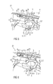
- FIG. 6 is a schematic view of one of the needle cavities and the reuse prevention mechanism in a third position
- FIG. 7 is a schematic view of one of the needle cavities and the reuse prevention mechanism in a fourth position
- FIG. 8 is a schematic view of the needle cavity magazine with the plurality of needle cavities and a needle chain with a plurality of cogs for resetting the reuse prevention mechanism.
- FIG. 1 is a schematic view of a needle storage arrangement 27 comprising a needle cavity magazine 1 with a plurality of needle cavities 2 and a reuse prevention mechanism 3 in a case 4 , wherein the reuse prevention mechanism 3 is in an initial first position P 1 .
- FIG. 2 is a schematic detail view of one of the needle cavities 2 and the reuse prevention mechanism 3 .
- the needle cavity 2 comprises a hollow body 2 . 1 adapted to receive an injection needle with a needle head (cf. FIG. 4 ).
- a cavity opening 2 . 2 in the body 2 . 1 allows for inserting and removing the injection needle with the needle head.
- the body 2 . 1 comprises a compliant clip arm 2 . 3 with a ledge radially inwardly protruding into the interior of the body 2 .
- the ledge comprises a ramp having an obtuse angle in one sense of rotation and a stop having an acute angle in an opposite sense of rotation.
- a lateral opening 2 . 4 is arranged in the body 2 . 1 .
- the needle cavity magazine 1 comprising the plurality of needle cavities 2 may be arranged as a needle chain such that the needle cavities 2 may be subsequently aligned with the access opening 5 by advancing the needle cavity magazine 1 .
- each needle cavity 2 may be connected to two adjacent needle cavities 2 , e.g. by a live hinge, such that the needle cavities 2 form a needle cavity magazine 1 in the shape of a needle chain.
- the reuse prevention mechanism 3 for controlling access to the needle cavities 2 in the needle cavity magazine 1 is arranged to prevent multiple uses of injection needles.
- the reuse prevention mechanism 3 is adapted to be placed between an access opening 5 in the case 4 and one of the needle cavities 2 aligned with the access opening 5 .
- the reuse prevention mechanism 3 comprises a detection arm 6 that is guided by a linear bearing 7 .
- the linear bearing 7 defines an axis which the reuse prevention mechanism 3 may be rotated about. This axis runs in a direction D substantially tangential with respect to a longitudinal axis A of the needle cavity 2 , which is respectively aligned with the access opening 5 .
- the detection arm 6 comprises a protrusion 6 . 1 with a ramp.
- a guidance contour 8 which may be implemented e.g. in the case 4 , is adapted to guide a pin 9 laterally arranged on a flexible guidance arm 10 .
- FIG. 3 is a schematic view of the guidance contour 8 adapted to control movement of the guidance pin 9 of the reuse prevention mechanism 3 .
- the guidance contour 8 comprises a one-way feature 8 . 1 with a substantially triangular profile preventing movement of the guidance pin 9 from a first position P 1 directly to a third position P 3 in the direction D but allowing movement in the opposite direction from the third position P 3 directly to the first position P 1 .
- a pre-stressed spring 11 e.g. a compression spring, is arranged to generate a force to drive the detection arm 6 in the direction D. Furthermore, the spring 11 applies a torque to the detection arm 6 in a sense S of rotation biasing the protrusion 6 . 1 of the detection arm 6 through the lateral opening 2 . 4 into the needle cavity 2 .
- FIG. 4 is a schematic perspective view of an exemplary embodiment of an injection needle 12 and an injection device 20 .
- the injection needle 12 comprises a needle head 13 .
- the needle head 13 substantially has the shape of a hollow cylinder closed at one end, in which the needle 12 is coaxially arranged, such that a proximal tip 12 . 1 of the needle 12 adapted to pierce a septum 21 on the injection device 20 or cartridge protrudes into the needle head 13 and a distal tip 12 . 2 of the needle 12 adapted to penetrate an injection site extends from the needle head 13 .
- a thread 14 is arranged on an inner surface 15 of the needle head 13 .
- the thread 14 is adapted to interface with a corresponding thread 22 on the injection device 20 .
- An outer surface 16 of the needle head 13 may comprise a number of longitudinal fins 17 spaced from each other by gaps 18 and distributed around the circumference of the needle head 13 , such that fins 17 and gaps 18 alternate.
- the fins 17 are uniformly spaced.
- the fins 17 and gaps 18 may interface with the compliant clip arm 2 . 3 in the needle cavity 2 which may be adapted to constrain rotation of the needle head 13 within the cavity 2 when the needle 12 is being screwed onto the injection device 20 but to allow rotation of the needle head 13 within the cavity 2 when a predetermined force of the fin 17 on the compliant clip arm 2 .
- the compliant clip arm 2 . 3 may be adapted to prevent rotation of the needle head 13 within the cavity 2 when the needle 12 is being unscrewed from an injection device 20 .
- the reuse prevention mechanism 3 is adapted to allow inserting an injection device 20 , e.g. a pen injector to pick up a new needle 12 and disables the reuse of one-time discarded needles 12 . By removing the needle 12 of the needle cavity 2 , reuse prevention is activated. After deposition of the used needle 12 the reuse prevention mechanism 3 blocks access for the injection device 20 . The procedure restarts when an unused needle 12 is carried towards the access opening 5 , e.g. by rotating the needle cavity magazine 1 .
- the guidance pin 9 stands in a first position P 1 of the guidance contour 8 .
- the protrusion 6 . 1 of the detection arm 6 is prevented from entering the needle cavity 2 by laterally abutting the needle head 13 .
- the injection device 20 is inserted into the needle cavity 2 , screwed on the needle thread 14 and pulled out of the case 4 .
- FIG. 5 is a schematic view of one of the needle cavities 2 and the reuse prevention mechanism 3 in the second position P 2 . In the second position P 2 the injection device 20 with the attached needle 12 is still able to enter the needle cavity 2 due to the ramp on the protrusion 6 . 1 of the detection arm 6 .
- FIG. 6 is a schematic view of one of the needle cavities and the reuse prevention mechanism 3 in the third position P 3 .
- the injection device 20 may be screwed off the needle 12 and subsequently be removed from the needle cavity 2 for the second time such that the surface 19 of the reuse prevention mechanism 3 is no longer blocked from moving further in the direction D.
- the reuse prevention mechanism 3 can thus slide into a final fourth position P 4 with the blocking part 26 at least partially blocking the access opening 5 such that the injection device 20 cannot be re-inserted.
- FIG. 7 is a schematic view of one of the needle cavities 2 and the reuse prevention mechanism 3 in the fourth position P 4 .
- the reuse prevention mechanism 3 or its blocking part 26 visible in the access opening 5 in the fourth position P 4 may comprise a sign colour (e.g. red), indicating the locking status to the user.
- FIG. 8 is a schematic view of the needle cavity magazine 1 with the plurality of needle cavities 2 and a needle cavity magazine 1 in the shape of a circular needle chain with a plurality of cogs 24 for resetting the reuse prevention mechanism 3 .
- the needle cavity magazine 1 may comprise a plurality of cogs 24 arranged to be engaged by a drive (not illustrated) for conveying the needle cavity magazine 1 .
- the cogs 24 on the needle cavity magazine 1 are adapted to mesh with a nose 25 on the inside of the detection arm 6 .
- the detection arm 6 and the whole reuse prevention mechanism 3 can only move in and opposite the direction D due to the linear bearing 7 . Furthermore, the detection arm 6 cannot rotate due to the guidance pin 9 being engaged to the guidance contour 8 and the needle head 13 blocking the protrusion 6 . 1 .
- the guidance pin 9 moves on the track from the fourth position P 4 via the third position P 3 to the first position P 1 .
- This movement is possible, as the guidance arm 10 is flexible and the shape of both—the guidance contour 8 and the guidance pin 9 —is inclined in a resetting-direction, i.e. opposite the direction D.
- the reuse prevention mechanism 3 is moved further than the first position P 1 .
- the cog 24 follows a circular path and the nose 25 follows a linear path, the paths diverge on sufficient movement of the cog 24 such that the cog 24 disengages the nose 25 and releases the reuse prevention mechanism 3 .
- the reuse prevention mechanism 3 is moved to the first position P 1 by the spring 11 .
- the reuse prevention mechanism 3 prevents multiple uses of injection needles 12 .
- An easily noticeable barrier signalizes the user that a used needle 12 is not accessible any more.
- the cutting point between needle 12 and needle cavity 2 is traced, which improves the deposition detection of the needle 12 .
Landscapes
- Health & Medical Sciences (AREA)
- Engineering & Computer Science (AREA)
- Hematology (AREA)
- Anesthesiology (AREA)
- Biomedical Technology (AREA)
- Heart & Thoracic Surgery (AREA)
- Vascular Medicine (AREA)
- Life Sciences & Earth Sciences (AREA)
- Animal Behavior & Ethology (AREA)
- General Health & Medical Sciences (AREA)
- Public Health (AREA)
- Veterinary Medicine (AREA)
- Environmental & Geological Engineering (AREA)
- Infusion, Injection, And Reservoir Apparatuses (AREA)
Applications Claiming Priority (4)
| Application Number | Priority Date | Filing Date | Title |
|---|---|---|---|
| EP13177489.5 | 2013-07-22 | ||
| EP13177489.5A EP2829294A1 (fr) | 2013-07-22 | 2013-07-22 | Mécanisme de prévention d'une réutilisation |
| EP13177489 | 2013-07-22 | ||
| PCT/EP2014/065419 WO2015011021A1 (fr) | 2013-07-22 | 2014-07-17 | Mécanisme de prévention de réutilisation |
Publications (2)
| Publication Number | Publication Date |
|---|---|
| US20160151587A1 US20160151587A1 (en) | 2016-06-02 |
| US10159804B2 true US10159804B2 (en) | 2018-12-25 |
Family
ID=48808231
Family Applications (1)
| Application Number | Title | Priority Date | Filing Date |
|---|---|---|---|
| US14/906,596 Expired - Fee Related US10159804B2 (en) | 2013-07-22 | 2014-07-17 | Reuse prevention mechanism |
Country Status (4)
| Country | Link |
|---|---|
| US (1) | US10159804B2 (fr) |
| EP (2) | EP2829294A1 (fr) |
| JP (1) | JP2016525402A (fr) |
| WO (1) | WO2015011021A1 (fr) |
Families Citing this family (1)
| Publication number | Priority date | Publication date | Assignee | Title |
|---|---|---|---|---|
| EP3517153A1 (fr) * | 2018-01-24 | 2019-07-31 | Insulcloud, S.L. | Dispositif de surveillance avec adaptateur universel pour stylos d'injection de médicaments |
Citations (6)
| Publication number | Priority date | Publication date | Assignee | Title |
|---|---|---|---|---|
| US5873462A (en) | 1997-09-12 | 1999-02-23 | Becton Dickinson And Company | Pen needle dispenser |
| US20030078543A1 (en) * | 2000-05-15 | 2003-04-24 | Luc Bergeron | Device for separating the connecting end of a hypodermic needle from the tip of an injection instrument |
| US7134550B2 (en) * | 2000-08-03 | 2006-11-14 | Novo Nordisk A/S | Needle magazine |
| GB2459772A (en) | 2008-05-06 | 2009-11-11 | Nicholas Harrison | A rotary dispenser with an internal carousel with a radial array of storage compartments |
| EP2514457A1 (fr) | 2011-04-21 | 2012-10-24 | Sanofi-Aventis Deutschland GmbH | Dispositif d'injection avec magasin linéaire de modules de médicament |
| EP2517744A1 (fr) | 2011-04-29 | 2012-10-31 | Sanofi-Aventis Deutschland GmbH | Mécanisme de prévention de réutilisation d'ensemble d'aiguille |
-
2013
- 2013-07-22 EP EP13177489.5A patent/EP2829294A1/fr not_active Withdrawn
-
2014
- 2014-07-17 WO PCT/EP2014/065419 patent/WO2015011021A1/fr active Application Filing
- 2014-07-17 JP JP2016528445A patent/JP2016525402A/ja active Pending
- 2014-07-17 US US14/906,596 patent/US10159804B2/en not_active Expired - Fee Related
- 2014-07-17 EP EP14739487.8A patent/EP3024518B1/fr not_active Not-in-force
Patent Citations (7)
| Publication number | Priority date | Publication date | Assignee | Title |
|---|---|---|---|---|
| US5873462A (en) | 1997-09-12 | 1999-02-23 | Becton Dickinson And Company | Pen needle dispenser |
| US20030078543A1 (en) * | 2000-05-15 | 2003-04-24 | Luc Bergeron | Device for separating the connecting end of a hypodermic needle from the tip of an injection instrument |
| US7134550B2 (en) * | 2000-08-03 | 2006-11-14 | Novo Nordisk A/S | Needle magazine |
| GB2459772A (en) | 2008-05-06 | 2009-11-11 | Nicholas Harrison | A rotary dispenser with an internal carousel with a radial array of storage compartments |
| WO2009136193A1 (fr) * | 2008-05-06 | 2009-11-12 | Nicholas Harrison | Distributeur d’aiguilles rotatif |
| EP2514457A1 (fr) | 2011-04-21 | 2012-10-24 | Sanofi-Aventis Deutschland GmbH | Dispositif d'injection avec magasin linéaire de modules de médicament |
| EP2517744A1 (fr) | 2011-04-29 | 2012-10-31 | Sanofi-Aventis Deutschland GmbH | Mécanisme de prévention de réutilisation d'ensemble d'aiguille |
Non-Patent Citations (2)
| Title |
|---|
| International Preliminary Report on Patentability in International Application No. PCT/EP2014/065419, dated Jan. 26, 2016, 6 pages. |
| International Search Report and Written Opinion in International Application No. PCT/EP2014/065419, dated Oct. 6, 2014, 9 pages. |
Also Published As
| Publication number | Publication date |
|---|---|
| JP2016525402A (ja) | 2016-08-25 |
| EP3024518A1 (fr) | 2016-06-01 |
| EP2829294A1 (fr) | 2015-01-28 |
| US20160151587A1 (en) | 2016-06-02 |
| EP3024518B1 (fr) | 2019-01-30 |
| WO2015011021A1 (fr) | 2015-01-29 |
Similar Documents
| Publication | Publication Date | Title |
|---|---|---|
| CN110559523B (zh) | 安全注射器 | |
| US20140171830A1 (en) | Needle Retraction Apparatus | |
| US11819663B2 (en) | Auto-injection drug delivery device | |
| RU2014109851A (ru) | Автоматический инъектор для инъекции эпинефрина | |
| US10661020B2 (en) | Medication delivery device | |
| JP2014526356A (ja) | 針安全デバイス | |
| EP2596825A1 (fr) | Dispositif de fixation et de retrait d'un ensemble formant aiguille | |
| CA2836625A1 (fr) | Dispositif de retrait d'ensemble aiguille | |
| US10159804B2 (en) | Reuse prevention mechanism | |
| GB2515032A (en) | Guide for an injection device | |
| JP6360834B2 (ja) | 薬剤容器キャリア | |
| JP6074418B2 (ja) | ニードル・アセンブリ・システム |
Legal Events
| Date | Code | Title | Description |
|---|---|---|---|
| AS | Assignment |
Owner name: SANOFI-AVENTIS DEUTSCHLAND GMBH, GERMANY Free format text: ASSIGNMENT OF ASSIGNORS INTEREST;ASSIGNOR:DASBACH, UWE;REEL/FRAME:040688/0840 Effective date: 20140818 |
|
| STCF | Information on status: patent grant |
Free format text: PATENTED CASE |
|
| FEPP | Fee payment procedure |
Free format text: MAINTENANCE FEE REMINDER MAILED (ORIGINAL EVENT CODE: REM.); ENTITY STATUS OF PATENT OWNER: LARGE ENTITY |
|
| LAPS | Lapse for failure to pay maintenance fees |
Free format text: PATENT EXPIRED FOR FAILURE TO PAY MAINTENANCE FEES (ORIGINAL EVENT CODE: EXP.); ENTITY STATUS OF PATENT OWNER: LARGE ENTITY |
|
| STCH | Information on status: patent discontinuation |
Free format text: PATENT EXPIRED DUE TO NONPAYMENT OF MAINTENANCE FEES UNDER 37 CFR 1.362 |
|
| FP | Lapsed due to failure to pay maintenance fee |
Effective date: 20221225 |