US10156707B2 - Zoom lens, optical apparatus and method for manufacturing the zoom lens - Google Patents
Zoom lens, optical apparatus and method for manufacturing the zoom lens Download PDFInfo
- Publication number
- US10156707B2 US10156707B2 US14/911,065 US201414911065A US10156707B2 US 10156707 B2 US10156707 B2 US 10156707B2 US 201414911065 A US201414911065 A US 201414911065A US 10156707 B2 US10156707 B2 US 10156707B2
- Authority
- US
- United States
- Prior art keywords
- lens
- lens group
- end state
- denotes
- refractive power
- Prior art date
- Legal status (The legal status is an assumption and is not a legal conclusion. Google has not performed a legal analysis and makes no representation as to the accuracy of the status listed.)
- Active
Links
Images


Classifications
-
- G—PHYSICS
- G02—OPTICS
- G02B—OPTICAL ELEMENTS, SYSTEMS OR APPARATUS
- G02B15/00—Optical objectives with means for varying the magnification
- G02B15/14—Optical objectives with means for varying the magnification by axial movement of one or more lenses or groups of lenses relative to the image plane for continuously varying the equivalent focal length of the objective
- G02B15/144—Optical objectives with means for varying the magnification by axial movement of one or more lenses or groups of lenses relative to the image plane for continuously varying the equivalent focal length of the objective having four groups only
- G02B15/1441—Optical objectives with means for varying the magnification by axial movement of one or more lenses or groups of lenses relative to the image plane for continuously varying the equivalent focal length of the objective having four groups only the first group being positive
- G02B15/144113—Optical objectives with means for varying the magnification by axial movement of one or more lenses or groups of lenses relative to the image plane for continuously varying the equivalent focal length of the objective having four groups only the first group being positive arranged +-++
-
- G—PHYSICS
- G02—OPTICS
- G02B—OPTICAL ELEMENTS, SYSTEMS OR APPARATUS
- G02B15/00—Optical objectives with means for varying the magnification
- G02B15/14—Optical objectives with means for varying the magnification by axial movement of one or more lenses or groups of lenses relative to the image plane for continuously varying the equivalent focal length of the objective
-
- G—PHYSICS
- G02—OPTICS
- G02B—OPTICAL ELEMENTS, SYSTEMS OR APPARATUS
- G02B13/00—Optical objectives specially designed for the purposes specified below
- G02B13/001—Miniaturised objectives for electronic devices, e.g. portable telephones, webcams, PDAs, small digital cameras
- G02B13/009—Miniaturised objectives for electronic devices, e.g. portable telephones, webcams, PDAs, small digital cameras having zoom function
-
- G—PHYSICS
- G02—OPTICS
- G02B—OPTICAL ELEMENTS, SYSTEMS OR APPARATUS
- G02B13/00—Optical objectives specially designed for the purposes specified below
- G02B13/18—Optical objectives specially designed for the purposes specified below with lenses having one or more non-spherical faces, e.g. for reducing geometrical aberration
-
- G—PHYSICS
- G02—OPTICS
- G02B—OPTICAL ELEMENTS, SYSTEMS OR APPARATUS
- G02B15/00—Optical objectives with means for varying the magnification
- G02B15/14—Optical objectives with means for varying the magnification by axial movement of one or more lenses or groups of lenses relative to the image plane for continuously varying the equivalent focal length of the objective
- G02B15/144—Optical objectives with means for varying the magnification by axial movement of one or more lenses or groups of lenses relative to the image plane for continuously varying the equivalent focal length of the objective having four groups only
- G02B15/1441—Optical objectives with means for varying the magnification by axial movement of one or more lenses or groups of lenses relative to the image plane for continuously varying the equivalent focal length of the objective having four groups only the first group being positive
- G02B15/144105—Optical objectives with means for varying the magnification by axial movement of one or more lenses or groups of lenses relative to the image plane for continuously varying the equivalent focal length of the objective having four groups only the first group being positive arranged +-+-
-
- G—PHYSICS
- G02—OPTICS
- G02B—OPTICAL ELEMENTS, SYSTEMS OR APPARATUS
- G02B15/00—Optical objectives with means for varying the magnification
- G02B15/14—Optical objectives with means for varying the magnification by axial movement of one or more lenses or groups of lenses relative to the image plane for continuously varying the equivalent focal length of the objective
- G02B15/16—Optical objectives with means for varying the magnification by axial movement of one or more lenses or groups of lenses relative to the image plane for continuously varying the equivalent focal length of the objective with interdependent non-linearly related movements between one lens or lens group, and another lens or lens group
- G02B15/20—Optical objectives with means for varying the magnification by axial movement of one or more lenses or groups of lenses relative to the image plane for continuously varying the equivalent focal length of the objective with interdependent non-linearly related movements between one lens or lens group, and another lens or lens group having an additional movable lens or lens group for varying the objective focal length
Definitions
- the present invention relates to a zoom lens, an optical apparatus and a method for manufacturing the zoom lens.
- a zoom lens according to a first aspect of the invention has, in order from an object: a first lens group having positive refractive power; a second lens group having negative refractive power; a third lens group having positive refractive power; and a fourth lens group having positive refractive power.
- the first lens group is constituted by a set of cemented lenses
- the third lens group is constituted by, in order from the object, a positive lens and a negative lens, and the following conditional expression being satisfied: 0.50 ⁇ TL/ft ⁇ 1.28 where TL denotes a total length of the zoom lens in the telephoto end state, and ft denotes a focal length of the zoom lens in the telephoto end state.
- fG1 denotes a focal length of the first lens group
- fG4 denotes a focal length of the fourth lens group
- ft denotes a focal length of the zoom lens in the telephoto end state
- dG1 denotes a thickness of the first lens group on the optical axis.
- the first lens group is constituted by, in order from the object, a lens having negative refractive power and a lens having positive refractive power
- the second lens group is constituted by, in order from the object, a lens having negative refractive power, a lens having negative refractive power, and a lens having positive refractive power
- ⁇ D2 denotes a distance on the optical axis from a lens surface closest to the object to a lens surface closest to an image in the second lens group
- ft denotes a focal length of the zoom lens in the telephoto end state
- fw denotes a focal length of the zoom lens in the wide-angle end state
- f4 denotes a focal length of the fourth lens group.
- the first lens group is constituted by, in order from the object, a lens having negative refractive power and a lens having positive refractive power, and the following conditional expressions are satisfied: ⁇ 0.25 ⁇ M 2/ fw ⁇ 1.10 3.0 ⁇ fL 2/ fw ⁇ 4.5
- M2 denotes a moving distance of the second lens group upon zooming from the wide-angle end state to the telephoto end state (where a direction toward an image plane is positive)
- fw denotes a focal length of the zoom lens in the wide-angle end state
- fL2 denotes a focal length of the lens having positive refractive power included in the first lens group.
- the first lens group is constituted by a negative lens and a positive lens
- the second lens group is constituted by, in order from the object, a negative lens, a negative lens and a positive lens
- the third lens group is constituted by a positive lens and a negative lens
- the following conditional expressions are satisfied: ⁇ 1.50 ⁇ ( G 2 R 2+ G 2 R 1)/( G 2 R 2 ⁇ G 2 R 1) ⁇ 0.10 ⁇ 2.00 ⁇ ( G 3 R 2+ G 3 R 1)/( G 3 R 2 ⁇ G 3 R 1) ⁇ 0.50
- G2R1 denotes a radius of curvature of an object side lens surface of the negative lens disposed on an image side of the second lens group
- G2R2 denotes a radius of curvature of an image side lens surface of the negative lens disposed on the image side of the second lens group
- G3R1 denotes a radius of curvature of an object side lens surface of the negative lens of the third lens group
- the zoom lens according to the first aspect of the invention it is preferable that upon zooming from the wide-angle end state to the telephoto end state, the second lens group moves to an image side first, and then moves to an object side.
- the fourth lens group moves to an object side first, and then moves to an image side.
- the zoom lens according to the first aspect of the invention it is preferable that the following conditional expression is satisfied: 1.00 ⁇ fG 1/( fw ⁇ ft ) 1/2 ⁇ 2.10 where fG1 denotes a focal length of the first lens group, and fw denotes a focal length of the zoom lens in the wide-angle end state.
- the second lens group is constituted by a negative lens, a negative lens and a positive lens.
- the fourth lens group is constituted by one positive lens.
- the third lens group includes at least one aspherical lens.
- the second lens group includes at least one aspherical lens.
- the fourth lens group includes at least one aspherical lens.
- the first lens group includes at least one aspherical lens.
- a zoom lens according to a second aspect of the invention has, in order from an object: a first lens group having positive refractive power; a second lens group having negative refractive power; a third lens group having positive refractive power; and a fourth lens group having positive refractive power.
- a distance between the first lens group and the second lens group changes, a distance between the second lens group and the third lens group changes, a distance between the third lens group and the fourth lens group changes, and at least the first lens group moves, and the following conditional expressions are satisfied: 0.1 ⁇ fG 1/ fG 4 ⁇ 1.0 10.0 ⁇ ft/dG 1 ⁇ 16.0
- fG1 denotes a focal length of the first lens group
- fG4 denotes a focal length of the fourth lens group
- ft denotes a focal length of the zoom lens in the telephoto end state
- dG1 denotes a thickness of the first lens group on the optical axis.
- the first lens group is constituted by, in order from the object, a lens having negative refractive power and a lens having positive refractive power
- the second lens group is constituted by, in order from the object, a lens having negative refractive power, a lens having negative refractive power, and a lens having positive refractive power
- ⁇ D2 denotes a distance on the optical axis from a lens surface closest to the object to a lens surface closest to an image in the second lens group
- ft denotes a focal length of the zoom lens in the telephoto end state
- fw denotes a focal length of the zoom lens in the wide-angle end state
- f4 denotes a focal length of the fourth lens group.
- the first lens group is constituted by, in order from the object, a lens having negative refractive power and a lens having positive refractive power, and the following conditional expressions are satisfied: ⁇ 0.25 ⁇ M 2/ fw ⁇ 1.10 3.0 ⁇ fL 2/ fw ⁇ 4.5
- M2 denotes a moving distance of the second lens group upon zooming from the wide-angle end state to the telephoto end state (where a direction toward an image plane is positive)
- fw denotes a focal length of the zoom lens in the wide-angle end state
- fL2 denotes a focal length of the lens having positive refractive power included in the first lens group.
- the first lens group is constituted by a negative lens and a positive lens
- the second lens group is constituted by, in order from the object, a negative lens, a negative lens and a positive lens
- the third lens group is constituted by a positive lens and a negative lens
- the following conditional expressions are satisfied: ⁇ 1.50 ⁇ ( G 2 R 2+ G 2 R 1)/( G 2 R 2 ⁇ G 2 R 1) ⁇ 0.10 ⁇ 2.00 ⁇ ( G 3 R 2+ G 3 R 1)/( G 3 R 2 ⁇ G 3 R 1) ⁇ 0.50
- G2R1 denotes a radius of curvature of an object side lens surface of the negative lens disposed on an image side of the second lens group
- G2R2 denotes a radius of curvature of an image side lens surface of the negative lens disposed on the image side of the second lens group
- G3R1 denotes a radius of curvature of an object side lens surface of the negative lens of the third lens group
- G3R2 denotes a radius of curvature of an image side lens surface of the negative lens of the third lens group.
- the first lens group is constituted by a negative lens and a positive lens.
- the third lens group is constituted by, in order from the object, a positive lens and a negative lens.
- the second lens group is constituted by a negative lens, a negative lens and a positive lens.
- the fourth lens group is constituted by one positive lens.
- the zoom lens according to the second aspect of the invention it is preferable that the following conditional expression is satisfied: 1.00 ⁇ fG 1/( fw ⁇ ft ) 1/2 ⁇ 2.10 where fw denotes a focal length of the zoom lens in the wide-angle end state.
- the fourth lens group moves to an object side first, and then moves to an image side.
- the zoom lens according to the second aspect of the invention it is preferable that upon zooming from the wide-angle end state to the telephoto end state, the second lens group moves to an image side first, and then moves to an object side.
- the third lens group includes at least one aspherical lens.
- the second lens group includes at least one aspherical lens.
- the fourth lens group includes at least one aspherical lens.
- the first lens group includes at least one aspherical lens.
- a zoom lens according to a third aspect of the invention has, in order from an object: a first lens group having positive refractive power; a second lens group having negative refractive power; a third lens group having positive refractive power; and a fourth lens group having positive refractive power.
- the first lens group is constituted by, in order from the object, a lens having negative refractive power and a lens having positive refractive power
- the second lens group is constituted by, in order from the object, a lens having negative refractive power, a lens having negative refractive power and a lens having positive refractive power
- ⁇ D2 denotes a distance on the optical axis from a lens surface closest to the object to a lens surface closest to an image in the second lens group
- ft denotes a focal length of the zoom lens in the telephoto end state
- fw denotes a focal length of the zoom lens in the wide-angle end state
- f4 denotes a focal length of the fourth lens group.
- the third lens group is constituted by one single lens having positive refractive power and one single lens having negative refractive power.
- TLt denotes a total length of an optical system in the telephoto end state
- ft denotes a focal length of the zoom lens in the telephoto end state
- the zoom lens according to the third aspect of the invention it is preferable that the following conditional expression is satisfied: 0.16 ⁇ ( ⁇ f 2)/ f 1 ⁇ 0.40 where f1 denotes a focal length of the first lens group, and f2 denotes a focal length of the second lens group.
- the zoom lens according to the third aspect of the invention it is preferable that the following conditional expression is satisfied: 0.70 ⁇ f 4/ f 1 ⁇ 1.40 where f1 denotes a focal length of the first lens group, and f4 denotes a focal length of the fourth lens group.
- the zoom lens according to the third aspect of the invention it is preferable that upon zooming from the wide-angle end state to the telephoto end state, the first lens group, the second lens group, the third lens group, and the fourth lens group move.
- the lens having negative refractive power and the lens having positive refractive power, which constitute the first lens group, are cemented.
- the lens having negative refractive power, the lens having negative refractive power, and the lens having positive refractive power, which constitute the second lens group, are separated from each other by an air distance.
- the fourth lens group is constituted by one single lens having positive refractive power.
- an image side lens surface of the lens having positive refractive power, which constitutes the first lens group, is formed in an aspherical shape.
- At least one of lens surfaces of the lenses having negative refractive power, which constitute the second lens group, is formed in an aspherical shape.
- At least one of surfaces of the lenses, which constitute the third lens group, is formed in an aspherical shape.
- At least one of surfaces of the lenses, which constitute the fourth lens group, is formed in an aspherical shape.
- a medium of the lenses constituting the fourth lens group is plastic resin.
- the fourth lens group moves along the optical axis.
- a zoom lens according to a fourth aspect of the invention has, in order from an object, a first lens group having positive refractive power; a second lens group having negative refractive power; a third lens group having positive refractive power; and a fourth lens group having positive refractive power.
- the first lens group is constituted by, in order from the object, a lens having negative refractive power, and a lens having positive refractive power, and the following conditional expressions are satisfied: ⁇ 0.25 ⁇ M 2/ fw ⁇ 1.10 3.0 ⁇ fL 2/ fw ⁇ 4.5
- M2 denotes a moving distance of the second lens group upon zooming from the wide-angle end state to the telephoto end state (where a direction toward an image plane is positive)
- fw denotes a focal length of the zoom lens in the wide-angle end state
- fL2 denotes a focal length of the lens having positive refractive power included in the first lens group.
- the third lens group is constituted by one single lens having positive refractive power, and one single lens having negative refractive power.
- the third lens group includes a lens having negative refractive power, and the following conditional expression is satisfied: ⁇ 4.5 ⁇ ( R 72+ R 71)/( R 72 ⁇ R 71) ⁇ 0.1 where R71 denotes a radius of curvature of an object side lens surface of the lens having negative refractive power included in the third lens group, and R72 denotes a radius of curvature of an image side lens surface of the lens having negative refractive power included in the third lens group.
- TLt denotes a total length of an optical system in the telephoto end state
- ft denotes a focal length of the zoom lens in the telephoto end state
- the zoom lens according to the fourth aspect of the invention it is preferable that the following conditional expression is satisfied: 0.16 ⁇ ( ⁇ f 2)/ f 1 ⁇ 0.40 where f1 denotes a focal length of the first lens group, and f2 denotes a focal length of the second lens group.
- the zoom lens according to the fourth aspect of the invention it is preferable that the following conditional expression is satisfied: 0.70 ⁇ f 4/ f 1 ⁇ 1.40 where f1 denotes a focal length of the first lens group, and f4 denotes a focal length of the fourth lens group.
- the zoom lens according to the fourth aspect of the invention it is preferable that the following conditional expression is satisfied: 4.0 ⁇ f 1/ fw ⁇ 6.5 where f1 denotes a focal length of the first lens group, and fw denotes a focal length of the zoom lens in the wide-angle end state.
- the zoom lens according to the fourth aspect of the invention it is preferable that the following conditional expression is satisfied: ⁇ 0.4 ⁇ M 3/ ft ⁇ 0.05 where M3 denotes a moving distance of the third lens group upon zooming from the wide-angle end state to the telephoto end state (where the direction toward the image plane is positive), and ft denotes a focal length of the zoom lens in the telephoto end state.
- the second lens group is constituted by, in order from the object, a lens having negative refractive power, a lens having negative refractive power, and a lens having positive refractive power.
- the lens having negative refractive power, the lens having negative refractive power, and the lens having positive refractive power, which constitute the second lens group, are separated from each other by an air distance.
- At least one of lens surfaces of the lenses having negative refractive power, which constitute the second lens group, is formed in an aspherical shape.
- the lens having negative refractive power and the lens having positive refractive power, which constitute the first lens group, are cemented.
- the zoom lens according to the fourth aspect of the invention it is preferable that upon zooming from the wide-angle end state to the telephoto end state, the first lens group, the second lens group, the third lens group, and the fourth lens group move.
- the fourth lens group is constituted by a lens having positive refractive power.
- an image side lens surface of the lens having positive refractive power, which constitutes the first lens group, is formed in an aspherical shape.
- At least one of surfaces of the lenses, which constitute the third lens group, is formed in an aspherical shape.
- At least one of surfaces of the lenses, which constitute the fourth lens group, is formed in an aspherical shape.
- a medium of the lenses constituting the fourth lens group is plastic resin.
- the fourth lens group moves along the optical axis.
- a zoom lens according to a fifth aspect of the invention has, in order from an object: a first lens group having positive refractive power; a second lens group having negative refractive power; a third lens group having positive refractive power; and a fourth lens group having positive refractive power.
- the first lens group is constituted by a negative lens and a positive lens
- the second lens group is constituted by, in order from the object, a negative lens, a negative lens and a positive lens
- the third lens group is constituted by a positive lens and a negative lens
- the following conditional expressions are satisfied: ⁇ 1.50 ⁇ ( G 2 R 2+ G 2 R 1)/( G 2 R 2 ⁇ G 2 R 1) ⁇ 0.10 ⁇ 2.00 ⁇ ( G 3 R 2+ G 3 R 1)/( G 3 R 2 ⁇ G 3 R 1) ⁇ 0.50
- G2R1 denotes a radius of curvature of an object side lens surface of the negative lens disposed on an image side of the second lens group
- G2R2 denotes a radius of curvature of an image side lens surface of the negative lens disposed on the image side of the second lens group
- G3R1 denotes a radius of curvature of an object side lens surface of the negative lens of the third lens group
- G3R2 denotes a radius of
- the zoom lens according to the fifth aspect of the invention it is preferable that the following conditional expression is satisfied: 1.00 ⁇ fG 1/( fw ⁇ ft ) 1/2 ⁇ 2.10 where fG1 denotes a focal length of the first lens group, fw denotes a focal length of the zoom lens in the wide-angle end state, and ft denotes a focal length of the zoom lens in the telephoto end state.
- the fourth lens group is constituted by a positive lens.
- the fourth lens group moves to an object side first, and then moves to an image side.
- the third lens group includes at least one aspherical lens.
- the second lens group includes at least one aspherical lens.
- the fourth lens group includes at least one aspherical lens.
- the first lens group includes at least one aspherical lens.
- An optical apparatus according to the first aspect of the invention includes the zoom lens according to the first aspect of the invention.
- an optical apparatus according to the second aspect of the invention includes the zoom lens according to the second aspect of the invention
- an optical apparatus according to the third aspect of the invention includes the zoom lens according to the third aspect of the invention
- an optical apparatus according to the fourth aspect of the invention includes the zoom lens according to the fourth aspect of the invention
- an optical apparatus according to the fifth aspect of the invention includes the zoom lens according to the fifth aspect of the invention.
- a method for manufacturing a zoom lens according to the first aspect of the invention is a method for manufacturing a zoom lens having, in order from an object: a first lens group having positive refractive power; a second lens group having negative refractive power; a third lens group having positive refractive power; and a fourth lens group having positive refractive power.
- Each lens in a lens barrel is disposed so that upon zooming from a wide-angle end state to a telephoto end state, a distance between the first lens group and the second lens group changes, a distance between the second lens group and the third lens group changes, a distance beteen the third lens group and the fourth lens group changes, and at least the first lens group moves.
- the first lens group is constituted by a set of cemented lenses
- the third lens group is constituted by, in order from the object, a positive lens and a negative lens, and the following conditional expression is satisfied: 0.50 ⁇ TL/ft ⁇ 1.28 where TL denotes a total length of the zoom lens in the telephoto end state, and ft denotes a focal length of the zoom lens in the telephoto end state.
- a method for manufacturing a zoom lens according to the second aspect of the invention is a method for manufacturing a zoom lens having, in order from an object: a first lens group having positive refractive power; a second lens group having negative refractive power; a third lens group having positive refractive power; and a fourth lens group having positive refractive power.
- Each lens in a lens barrel is disposed so that upon zooming from a wide-angle end state to a telephoto end state, a distance between the first lens group and the second lens group changes, a distance between the second lens group and the third lens group changes, a distance beteen the third lens group and the fourth lens group changes, and at least the first lens group moves, and the following conditional expressions are satisfied: 0.1 ⁇ fG 1/ fG 4 ⁇ 1.0 10.0 ⁇ ft/dG 1 ⁇ 16.0 where fG1 denotes a focal length of the first lens group, fG4 denotes a focal length of the fourth lens group, ft denotes a focal length of the zoom lens in the telephoto end state, and dG1 denotes a thickness of the first lens group on the optical axis.
- a method for manufacturing a zoom lens according to the third aspect of the invention is a method for manufacturing a zoom lens having, in order from an object: a first lens group having positive refractive power; a second lens group having negative refractive power; a third lens group having positive refractive power; and a fourth lens group having positive refractive power.
- Each lens in a lens barrel is disposed so that upon zooming from a wide-angle end state to a telephoto end state, a distance between the first lens group and the second lens group changes, a distance between the second lens group and the third lens group changes, and a distance between the third lens group and the fourth lens group changes,
- the first lens group is constituted by, in order from the object, a lens having negative refractive power and a lens having positive refractive power
- the second lens group is constituted by, in order from the object, a lens having negative refractive power, a lens having negative refractive power, and a lens having positive refractive power, and the following conditional expressions are satisfied: 0.050 ⁇ D 2/ ft ⁇ 0.115 4.3 ⁇ f 4/ fw ⁇ 6.8 where ⁇ D2 denotes a distance on the optical axis from a lens surface closest to the object to a lens surface closest to an image in the second lens group, ft denotes a focal length of the zoom lens in
- a method for manufacturing a zoom lens according to the fourth aspect of the invention is a method for manufacturing a zoom lens having, in order from an object: a first lens group having positive refractive power; a second lens group having negative refractive power; a third lens group having positive refractive power; and a fourth lens group having positive refractive power.
- Each lens in a lens barrel is disposed so that upon zooming from a wide-angle end state to a telephoto end state, a distance between the first lens group and the second lens group changes, a distance between the second lens group and the third lens group changes, and a distance between the third lens group and the fourth lens group changes.
- the first lens group is constituted by, in order from the object, a lens having negative refractive power, and a lens having positive refractive power, and the following conditional expressions are satisfied: ⁇ 0.25 ⁇ M 2/ fw ⁇ 1.10 3.0 ⁇ fL 2/ fw ⁇ 4.5
- M2 denotes a moving distance of the second lens group upon zooming from the wide-angle end state to the telephoto end state (where a direction toward an image plane is positive)
- fw denotes a focal length of the zoom lens in the wide-angle end state
- fL2 denotes a focal length of the lens having positive refractive power included in the first lens group.
- a method for manufacturing a zoom lens according to the fifth aspect of the invention is a method for manufacturing a zoom lens having, in order from an object: a first lens group having positive refractive power; a second lens group having negative refractive power; a third lens group having positive refractive power; and a fourth lens group having positive refractive power.
- Each lens in a lens barrel is disposed so that upon zooming from a wide-angle end state to a telephoto end state, a distance between the first lens group and the second lens group changes, a distance between the second lens group and the third lens group changes, a distance between the third lens group and the fourth lens group changes, and at least the first lens group moves.
- the first lens group is constituted by a negative lens and a positive lens
- the second lens group is constituted by, in order from the object, a negative lens, a negative lens and a positive lens
- the third lens group is constituted by a positive lens and a negative lens
- the following conditional expressions are satisfied: ⁇ 1.50 ⁇ ( G 2 R 2+ G 2 R 1)/( G 2 R 2 ⁇ G 2 R 1) ⁇ 0.10 ⁇ 2.00 ⁇ ( G 3 R 2+ G 3 R 1)/( G 3 R 2 ⁇ G 3 R 1) ⁇ 0.50
- G2R1 denotes a radius of curvature of an object side lens surface of the negative lens disposed on an image side of the second lens group
- G2R2 denotes a radius of curvature of an image side lens surface of the negative lens disposed on the image side of the second lens group
- G3R1 denotes a radius of curvature of an object side lens surface of the negative lens of the third lens group
- G3R2 denotes a radius of
- Any one of the aspect of the invention can provide a compact zoom lens having high variable power, an optical apparatus including the zoom lens, and a method for manufacturing the zoom lens.
- Any one of the aspect of the invention can also provide a zoom lens having high optical performance, an optical apparatus including the zoom lens, and a method for manufacturing the zoom lens.
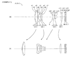
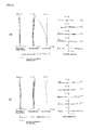
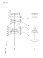
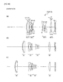
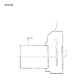
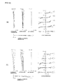
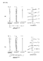
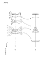
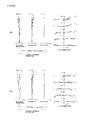
- FIG. 1 is a diagram depicting a configuration of a zoom lens according to Example 1 and the moving locus (arrow marks) of each lens group from a wide-angle end state (W) to a telephoto end state (T);
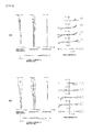
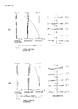
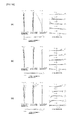
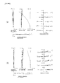
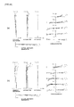
- FIG. 2 is a set of graphs showing various aberrations of the zoom lens according to Example 1, where FIG. 2( a ) is a set of graphs showing various aberrations of the zoom lens of Example 1 upon focusing on infinity in the wide-angle end state, and FIG. 2( b ) is a set of graphs showing various aberrations of the zoom lens upon focusing on infinity in the intermediate focal length state on the wide-angle end side;
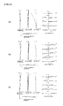
- FIG. 3 is a set of graphs showing various aberrations of the zoom lens according to Example 1, where FIG. 3( a ) is a set of graphs showing various aberrations of the zoom lens of Example 1 upon focusing on infinity in the intermediate focal length state on the telephoto end side, and FIG. 3( b ) is a set of graphs showing various aberrations of the zoom lens upon focusing on infinity in the telephoto end state;
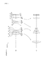
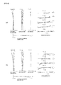
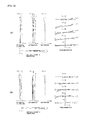
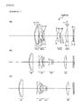
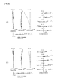
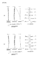
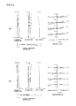
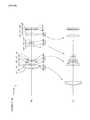
- FIG. 4 is a diagram depicting a configuration of a zoom lens according to Example 2 and the moving locus (arrow marks) of each lens group from a wide-angle end state (W) to a telephoto end state (T);
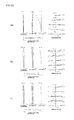
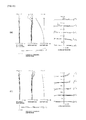
- FIG. 5 is a set of graphs showing various aberrations of the zoom lens according to Example 2, where FIG. 5( a ) is a set of graphs showing various aberrations of the zoom lens of Example 2 upon focusing on infinity in the wide-angle end state, and FIG. 5( b ) is a set of graphs showing various aberrations of the zoom lens upon focusing on infinity in the intermediate focal length state on the wide-angle end side;
- FIG. 6 is a set of graphs showing various aberrations of the zoom lens according to Example 2, where FIG. 6( a ) is a set of graphs showing various aberrations of the zoom lens of Example 2 upon focusing on infinity in the intermediate focal length state on the telephoto end side, and FIG. 6( b ) is a set of graphs showing various aberrations of the zoom lens upon focusing on infinity in the telephoto end state;
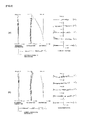
- FIG. 7 is a diagram depicting a configuration of a zoom lens according to Example 3 and the moving locus (arrow marks) of each lens group from a wide-angle end state (W) to a telephoto end state (T);
- FIG. 8 is a set of graphs showing various aberrations of the zoom lens according to Example 3, where FIG. 8( a ) is a set of graphs showing various aberrations of the zoom lens of Example 3 upon focusing on infinity in the wide-angle end state, and FIG. 8( b ) is a set of graphs showing various aberrations of the zoom lens upon focusing on infinity in the intermediate focal length state on the wide-angle end side;
- FIG. 9 is a set of graphs showing various aberrations of the zoom lens according to Example 3, where FIG. 9( a ) is a set of graphs showing various aberrations of the zoom lens of Example 3 upon focusing on infinity in the intermediate focal length state on the telephoto end side, and FIG. 9( b ) is a set of graphs showing various aberrations of the zoom lens upon focusing on infinity in the telephoto end state;
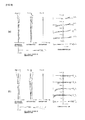
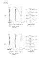
- FIG. 10 is a diagram depicting a configuration of a zoom lens according to Example 4 and the moving locus (arrow marks) of each lens group from a wide-angle end state (W) to a telephoto end state (T);
- FIG. 11 is a set of graphs showing various aberrations of the zoom lens according to Example 4, where FIG. 11( a ) is a set of graphs showing various aberrations of the zoom lens of Example 4 upon focusing on infinity in the wide-angle end state, and FIG. 11( b ) is a set of graphs showing various aberrations of the zoom lens upon focusing on infinity in the intermediate focal length state on the wide-angle end side;
- FIG. 12 is a set of graphs showing various aberrations of the zoom lens according to Example 4, where FIG. 12( a ) is a set of graphs showing various aberrations of the zoom lens of Example 4 upon focusing on infinity in the intermediate focal length state on the telephoto end side, and FIG. 12( b ) is a set of graphs showing various aberrations of the zoom lens upon focusing on infinity in the telephoto end state;
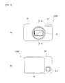
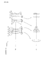
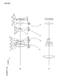
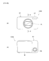
- FIG. 13( a ) is a front view of a digital still camera using the zoom lens according to Embodiment 1 or 2, and FIG. 13( b ) is a rear view of this digital still camera;
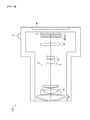
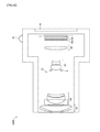
- FIG. 14 is a cross-sectional view along the arrow A-A′ in FIG. 13( a ) ;
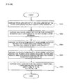
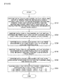
- FIG. 15 is a flow chart depicting a method for manufacturing the zoom lens according to Embodiment 1;
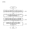
- FIG. 16 is a flow chart depicting a method for manufacturing the zoom lens according to Embodiment 2;
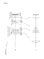
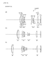
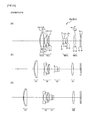
- FIG. 17 is a cross-sectional view depicting a lens configuration of a zoom lens according to Example 5, where FIG. 17( a ) indicates the wide-angle end state, FIG. 17( b ) indicates the intermediate focal length state, and FIG. 17( c ) indicates the telephoto end state;
- FIG. 18 is a set of graphs showing various aberrations of the zoom lens according to Example 5, where FIG. 18( a ) indicates the wide-angle end state, FIG. 18( b ) indicates the intermediate focal length state, and FIG. 18( c ) indicates the telephoto end state;
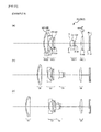
- FIG. 19 is a cross-sectional view depicting a lens configuration of a zoom lens according to Example 6, where FIG. 19( a ) indicates the wide-angle end state, FIG. 19( b ) indicates the intermediate focal length state, and FIG. 19( c ) indicates the telephoto end state;
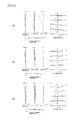
- FIG. 20 is a set of graphs showing various aberrations of the zoom lens according to Example 6, where FIG. 20( a ) indicates the wide-angle end state, FIG. 20( b ) indicates the intermediate focal length state, and FIG. 20( c ) indicates the telephoto end state;
- FIG. 21 is a cross-sectional view depicting a lens configuration of a zoom lens according to Example 7, where FIG. 21( a ) indicates the wide-angle end state, FIG. 21( b ) indicates the intermediate focal length state, and FIG. 21( c ) indicates the telephoto end state;
- FIG. 22 is a set of graphs showing various aberrations of the zoom lens according to Example 7, where FIG. 22( a ) indicates the wide-angle end state, FIG. 22( b ) indicates the intermediate focal length state, and FIG. 22( c ) indicates the telephoto end state;
- FIG. 23 is a cross-sectional view depicting a lens configuration of a zoom lens according to Example 8, where FIG. 23( a ) indicates the wide-angle end state, FIG. 23( b ) indicates the intermediate focal length state, and FIG. 23( c ) indicates the telephoto end state;
- FIG. 24 is a set of graphs showing various aberrations of the zoom lens according to Example 8, where FIG. 24( a ) indicates the wide-angle end state, FIG. 24( b ) indicates the intermediate focal length state, and FIG. 24( c ) indicates the telephoto end state;
- FIG. 25 is a cross-sectional view depicting a lens configuration of a zoom lens according to Example 9, where FIG. 25( a ) indicates the wide-angle end state, FIG. 25( b ) indicates the intermediate focal length state, and FIG. 25( c ) indicates the telephoto end state;
- FIG. 26 is a set of graphs showing various aberrations of the zoom lens according to Example 9, where FIG. 26( a ) indicates the wide-angle end state, FIG. 26( b ) indicates the intermediate focal length state, and FIG. 26( c ) indicates the telephoto end state;
- FIG. 27 is a cross-sectional view of a camera including the zoom lens according to Embodiment 3 or 4;
- FIG. 28 is a flow chart depicting a method for manufacturing the zoom lens according to Embodiment 3.
- FIG. 29 is a flow chart depicting a method for manufacturing the zoom lens according to Embodiment 4.
- FIG. 30 is a diagram depicting a configuration of a zoom lens according to Example 10 and the moving locus (arrow marks) of each lens group from a wide-angle end state (W) to a telephoto end state (T);
- FIG. 31 is a set of graphs showing various aberrations of the zoom lens according to Example 10, where FIG. 31( a ) is a set of graphs showing various aberrations of the zoom lens of Example 10 upon focusing on infinity in the wide-angle end state, and FIG. 31( b ) is a set of graphs showing various aberrations of the zoom lens upon focusing on infinity in the intermediate focal length state on the wide-angle end side;
- FIG. 32 is a set of graphs showing various aberrations of the zoom lens according to Example 10, where FIG. 32( a ) is a set of graphs showing various aberrations of the zoom lens of Example 1 upon focusing on infinity in the intermediate focal length state on the telephoto end side, and FIG. 32( b ) is a set of graphs showing various aberrations of the zoom lens upon focusing on infinity in the telephoto end state;
- FIG. 33 is a diagram depicting a configuration of a zoom lens according to Example 11 and the moving locus (arrow marks) of each lens group from a wide-angle end state (W) to a telephoto end state (T);
- FIG. 34 is a set of graphs showing various aberrations of the zoom lens according to Example 11, where FIG. 34( a ) is a set of graphs showing various aberrations of the zoom lens of Example 2 upon focusing on infinity in the wide-angle end state, and FIG. 34( b ) is a set of graphs showing various aberrations of the zoom lens upon focusing on infinity in the intermediate focal length state on the wide-angle end side;
- FIG. 35 is a set of graphs showing various aberrations of the zoom lens according to Example 11, where FIG. 35( a ) is a set of graphs showing various aberrations of the zoom lens of Example 2 upon focusing on infinity in the intermediate focal length state on the telephoto end side, and FIG. 35( b ) is a set of graphs showing various aberrations of the zoom lens upon focusing on infinity in the telephoto end state;
- FIG. 36 is a diagram depicting a configuration of a zoom lens according to Example 12 and the moving locus (arrow marks) of each lens group from a wide-angle end state (W) to a telephoto end state (T);
- FIG. 37 is a set of graphs showing various aberrations of the zoom lens according to Example 12, where FIG. 37( a ) is a set of graphs showing various aberrations of the zoom lens of Example 12 upon focusing on infinity in the wide-angle end state, and FIG. 37( b ) is a set of graphs showing various aberrations of the zoom lens upon focusing on infinity in the intermediate focal length state on the wide-angle end side;
- FIG. 38 is a set of graphs showing various aberrations of the zoom lens according to Example 12, where FIG. 38( a ) is a set of graphs showing various aberrations of the zoom lens of Example 12 upon focusing on infinity in the intermediate focal length state on the telephoto end side, and FIG. 38( b ) is a set of graphs showing various aberrations of the zoom lens upon focusing on infinity in the telephoto end state;
- FIG. 39 is a diagram depicting a configuration of a zoom lens according to Example 13 and the moving locus (arrow marks) of each lens group from a wide-angle end state (W) to a telephoto end state (T);
- FIG. 40 is a set of graphs showing various aberrations of the zoom lens according to Example 13, where FIG. 40( a ) is a set of graphs showing various aberrations of the zoom lens of Example 13 upon focusing on infinity in the wide-angle end state, and FIG. 40( b ) is a set of graphs showing various aberrations of the zoom lens upon focusing on infinity in the intermediate focal length state on the wide-angle end side;
- FIG. 41 is a set of graphs showing various aberrations of the zoom lens according to Example 13, where FIG. 41( a ) is a set of graphs showing various aberrations of the zoom lens of Example 13 upon focusing on infinity in the intermediate focal length state on the telephoto end side, and FIG. 41( b ) is a set of graphs showing various aberrations of the zoom lens upon focusing on infinity in the telephoto end state;
- FIG. 42 is a diagram depicting a configuration of a zoom lens according to Example 14 and the moving locus (arrow marks) of each lens group from a wide-angle end state (W) to a telephoto end state (T);
- FIG. 43 is a set of graphs showing various aberrations of the zoom lens according to Example 14, where FIG. 43( a ) is a set of graphs showing various aberrations of the zoom lens of Example 14 upon focusing on infinity in the wide-angle end state, and FIG. 43( b ) is a set of graphs showing various aberrations of the zoom lens upon focusing on infinity in the intermediate focal length state on the wide-angle end side;
- FIG. 44 is a set of graphs showing various aberrations of the zoom lens according to Example 14, where FIG. 44( a ) is a set of graphs showing various aberrations of the zoom lens of Example 14 upon focusing on infinity in the intermediate focal length state on the telephoto end side, and FIG. 44( b ) is a set of graphs showing various aberrations of the zoom lens upon focusing on infinity in the telephoto end state;
- FIG. 45 is a diagram depicting a configuration of a zoom lens according to Example 15 and the moving locus (arrow marks) of each lens group from a wide-angle end state (W) to a telephoto end state (T);
- FIG. 46 is a set of graphs showing various aberrations of the zoom lens according to Example 15, where FIG. 46( a ) is a set of graphs showing various aberrations of the zoom lens of Example 15 upon focusing on infinity in the wide-angle end state, and FIG. 46( b ) is a set of graphs showing various aberrations of the zoom lens upon focusing on infinity in the intermediate focal length state on the wide-angle end side;
- FIG. 47 is a set of graphs showing various aberrations of the zoom lens according to Example 15, where FIG. 47( a ) is a set of graphs showing various aberrations of the zoom lens of Example 15 upon focusing on infinity in the intermediate focal length state on the telephoto end side, and FIG. 47( b ) is a set of graphs showing various aberrations of the zoom lens upon focusing on infinity in the telephoto end state;
- FIG. 48( a ) is a front view of a digital still camera using the zoom lens according to Embodiment 5, and FIG. 48( b ) is a rear view of this digital still camera;
- FIG. 49 is a cross-sectional view along the arrow A-A′ in FIG. 48( a ) ;
- FIG. 50 is a flow chart depicting a method for manufacturing the zoom lens according to Embodiment 5.
- a zoom lens ZL according to Embodiment 1 has, in order from an object: a first lens group G 1 having positive refractive power; a second lens group G 2 having negative refractive power; a third lens group G 3 having positive refractive power; and a fourth lens group G 4 having positive refractive power.
- a distance between the first lens group and the second lens group changes, a distance between the second group and the third lens group changes, a distance between the third lens group and the fourth lens group changes, and at least the first lens group G 1 moves.
- the first lens group G 1 is constituted by a set of cemented lenses
- the third lens group G 3 is constituted by, in order from the object, a positive lens and a negative lens, and the following conditional expression (1) is satisfied.
- TL denotes a total length of the zoom lens ZL in the telephoto end state
- ft denotes a focal length of the zoom lens ZL in the telephoto end state.
- the first lens group G 1 By constituting the first lens group G 1 by a set of cemented lenses, lateral chromatic aberration and spherical aberration generated in the first lens group G 1 can be corrected well, and as a result, lateral chromatic aberration and spherical aberration in the telephoto end state can be corrected well. Further, by constituting the first lens group G 1 by one lens component, downsizing becomes possible. Furthermore, by constituting the first lens group G 1 only by the cemented lenses, manufacturing becomes easier than the case of arranging a plurality of lenses side by side. It is preferable that the set of cemented lenses of the first lens group G 1 is constituted by a negative lens and a positive lens, which are cemented in order from the object.
- the third lens group G 3 By constituting the third lens group G 3 by the positive lens and the negative lens in order from the object, the fluctuation of spherical aberration and longitudinal chromatic aberration due to zooming can be corrected well. Further, by constituting the third lens group G 3 by the two lenses, downsizing becomes possible. It is preferable that the lens surface closest to the object in the third lens group G 3 has a convex surface facing the object.
- the conditional expression (1) specifies a ratio between the total length TL of the zoom lens ZL in the telephoto end state (distance on the optical axis from the first surface of the lenses to the paraxial image plane in the telephoto end state) and the focal length ft of the zoom lens ZL in the telephoto end state. If the upper limit value of the conditional expression (1) is exceeded, the amount of lateral chromatic aberration and the amount of spherical aberration generated in the first lens group G 1 increase, and as a result, it becomes difficult to appropriately correct lateral chromatic aberration and spherical aberration in the telephoto end state, which is not desirable.
- conditional expression (1) If the lower limit value of the conditional expression (1) is not reached, astigmatism generated in each subsequent lens group after the first lens group G 1 increases, and as a result, it becomes difficult to correct astigmatism well in the entire zoom range, which is not desirable. If the conditional expression (1) is satisfied, a compact zoom lens ZL with high variable power, where various aberrations are corrected well, can be implemented.
- the upper limit value of the conditional expression (1) is preferably 1.27. To demonstrate the effect of Embodiment 1 with higher certainty, the upper limit value of the conditional expression (1) is preferably 1.26. To demonstrate the effect of Embodiment 1 to the maximum, the upper limit value of the conditional expression (1) is preferably 1.25.
- the lower limit value of the conditional expression (1) is preferably 0.70. To demonstrate the effect of Embodiment 1 with higher certainty, the lower limit value of the conditional expression (1) is 0.90.
- the zoom lens ZL according to Embodiment 1 it is preferable that upon zooming from the wide-angle end state to the telephoto end state, the second lens group G 2 moves toward the image first, and then moves toward the object.
- longitudinal chromatic aberration in the telephoto end state can be corrected well. If the second lens group G 2 is constructed only to move toward the image upon zooming, a sufficient moving distance of the second lens group G 2 or the third lens group G 3 cannot be secured, which may result in a drop in optical performance and an increase in total length of the zoom lens.
- the fourth lens group G 4 moves toward the object first, and then moves toward the image.
- the positions of the first lens group G 1 to the third lens group G 3 on the optical axis can be made closer to the image side in the telephoto end state, compared with the configuration of moving the fourth lens group G 4 only toward the object, which allows to decrease the moving distance of the first lens group G 1 , and to make the moving mechanism (e.g. barrel member) of each lens group shorter, that is, to decrease the total length of the zoom lens.
- the moving mechanism e.g. barrel member
- the zoom lens ZL according to Embodiment 1 it is preferable that the following conditional expression (2) is satisfied. 1.00 ⁇ fG 1/( fw ⁇ ft ) 1/2 ⁇ 2.10 (2) where fG1 denotes a focal length of the first lens group G 1 , and fw denotes a focal length of the zoom lens ZL in the wide-angle end state.
- the conditional expression (2) specifies the focal length fG1 of the first lens group G 1 using the focal length fw of the zoom lens ZL in the wide-angle end state, and the focal length ft of the zoom lens ZL in the telephoto end state. If the upper limit value of the conditional expression (2) is exceeded, astigmatism that generates in each subsequent lens group after the first lens group G 1 increases, and as a result, it becomes difficult to correct astigmatism well in the entire zoom range, which is not desirable.
- the upper limit value of the conditional expression (2) is preferably 2.08. To demonstrate the effect of Embodiment 1 with higher certainty, the upper limit value of the conditional expression (2) is preferably 2.07.
- the lower limit value of the conditional expression (2) is preferably 1.30.
- the lower limit value of the conditional expression (2) is preferably 1.50.
- the lower limit value of the conditional expression (2) is preferably 1.70.
- the second lens group G 2 is constituted by a negative lens, a negative lens and a positive lens.
- the arrangement of the lenses may be the negative lens, the negative lens, and the positive lens in order from the object.
- the arrangement of the lenses may also be the negative lens, the positive lens, and the negative lens in order from the object.
- the fourth lens group G 4 is constituted by one positive lens. By this configuration, fluctuation of astigmatism due to zooming can be corrected well.
- the third lens group G 3 includes at least one aspherical lens.
- the second lens group G 2 includes at least one aspherical lens.
- the fourth lens group G 4 includes at least one aspherical lens.
- the first lens group G 1 includes at least one aspherical lens.
- FIG. 13 and FIG. 14 show a configuration of a digital still camera CAM (optical apparatus), which is an optical apparatus including the zoom lens ZL according to Embodiment 1.
- a power button (not illustrated) of the digital still camera CAM is pressed, a shutter (not illustrated) of a photographing lens (zoom lens ZL) is released, and lights from an object are collected by the zoom lens ZL and form an image on a picture element C (e.g. CCD, CMOS), which is disposed on the image plane I (see FIG. 1 ).
- the object image formed on the picture element C is disposed on a liquid crystal monitor M, which is disposed on the back of the digital still camera CAM.
- the user determines the composition of the object image while viewing the liquid crystal monitor M, then presses a release button B 1 to photograph the object image by the picture element C, and stores it in memory (not illustrated).
- the camera CAM has an auxiliary light emitting unit EF, which emits auxiliary light when the object is dark, and a function button B 2 , which is used for setting various conditions for the digital still camera CAM.
- a compact type camera in which the camera CAM and the zoom lens ZL are integrated, was described as an example, but a single-lens reflex camera, where the lens barrel including the zoom lens ZL is detachable from the camera body, may be used as the optical apparatus.
- a compact camera having high variable power can be implemented by including the above mentioned zoom lens ZL as the photographing lens.
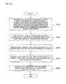
- each lens is disposed in a lens barrel, so that the first lens group having positive refractive power, the second lens group having negative refractive power, the third lens group having positive refractive power, and the fourth lens group having positive refractive power are arranged in order from the object (step ST 10 ).
- each lens is disposed so that, upon zooming from the wide-angle end state to the telephoto end state, the distance between the first lens group and the second lens group changes, the distance between the second lens group and the third lens group changes, the distance between the third lens group and the fourth lens group changes, and at least the first lens group G 1 moves (step ST 20 ).
- Each lens is disposed in the lens barrel so that the first lens group G 1 is constituted by a set of cemented lenses (step ST 30 ).
- Each lens is disposed in the lens barrel so that the third lens group G 3 is constituted by, in order from the object, a positive lens and a negative lens (step ST 40 ). Then each lens is disposed in the lens barrel so that the following conditional expression (1) is satisfied (step ST 50 ). 0.50 ⁇ TL/ft ⁇ 1.28 (1) where TL denotes a total length of the zoom lens in the telephoto end state, and ft denotes a focal length of the zoom lens in the telephoto end state.
- a set of cemented lenses constituted by, in order from the object, a negative meniscus lens L 11 having a convex surface facing the object and a biconvex positive lens L 12 is disposed in the lens barrel.
- the second lens group G 2 having negative refractive power each lens is disposed in the lens barrel so that a biconcave negative lens L 21 , a biconcave negative lens L 22 and a positive meniscus lens L 23 having a convex surface facing the object are arranged in order from the object.
- each lens is disposed in the lens barrel so that a biconvex positive lens L 31 , and a negative meniscus lens L 32 having a convex surface facing the object are arranged in order from the object.
- a biconvex positive lens L 41 is disposed in the lens barrel.
- Each lens is disposed in the lens barrel so that the above mentioned conditional expression (1) is satisfied (the correspondence value of the conditional expression (1) is 1.247).
- a compact zoom lens having high variable power can be manufactured.
- a zoom lens ZL according to Embodiment 2 has, in order from an object: a first lens group G 1 having positive refractive power; a second lens group G 2 having negative refractive power; a third lens group G 3 having positive refractive power; and a fourth lens group G 4 having positive refractive power.
- a distance between the first lens group and the second lens group changes, a distance between the second lens group and the third lens group changes, a distance between the third lens group and the fourth lens group changes, and at least the first lens group G 1 moves, and the following conditional expressions (3) and (4) are satisfied.
- fG1 denotes a focal length of the first lens group G 1
- fG4 denotes a focal length of the fourth lens group G 4
- ft denotes a focal length of the zoom lens ZL in the telephoto end state
- dG1 denotes a thickness of the first lens group G 1 on the optical axis.
- the conditional expression (3) specifies a ratio between the focal length fG1 of the first lens group G 1 and the focal length fG4 of the fourth lens group G 4 . If the upper limit value of the conditional expression (3) is exceeded, astigmatism generated in each subsequent lens group after the first lens group G 1 increases, and as a result, it becomes difficult to appropriately correct astigmatism in the entire zoom range, which is not desirable. If the lower limit value of the conditional expression (3) is not reached, the amount of lateral chromatic aberration and the amount of spherical aberration generated in the first lens group G 1 increase, and as a result, it becomes difficult to appropriately correct lateral chromatic aberration and spherical aberration in the telephoto end state, which is not desirable.
- the upper limit value of the conditional expression (3) is preferably 0.98. To demonstrate the effect of Embodiment 2 with higher certainty, the upper limit value of the conditional expression (3) is preferably 0.90.
- the lower limit value of the conditional expression (3) is preferably 0.3.
- the lower limit value of the conditional expression (3) is preferably 0.6.
- the conditional expression (4) specifies a ratio between the focal length ft of the zoom lens in the telephoto end state, and the thickness dG1 of the first lens group G 1 on the optical axis (distance on the optical axis from the first surface to the last surface of the lenses constituting the first lens group G 1 ). If the upper limit value of the conditional expression (4) is exceeded, the amount of lateral chromatic aberration and the amount of spherical aberration generated in the first lens group G 1 increase, and as a result, it becomes difficult to appropriately correct lateral chromatic aberration and spherical aberration in the telephoto end state, which is not desirable.
- the upper limit value of the conditional expression (4) is preferably 15.0. To demonstrate the effect of Embodiment 2 with higher certainty, the upper limit value of the conditional expression (4) is preferably 14.0.
- the lower limit value of the conditional expression (4) is preferably 11.0. To demonstrate the effect of Embodiment 2 with higher certainty, the lower limit value of the conditional expression (4) is preferably 12.0.
- the first lens group G 1 is constituted by a negative lens and a positive lens.
- spherical aberration and lateral chromatic aberration generated in the first lens group G 1 can be corrected well, and as a result, spherical aberration and lateral chromatic aberration in the telephoto end state can be corrected well.
- the first lens group G 1 is constituted by a set of cemented lenses where a negative lens and a positive lens are cemented in order from the object. By constructing the first lens group G 1 by one lens component like this, manufacturing is easier than arranging a plurality of lenses side by side.
- the third lens group G 3 is constituted by, in order from the object, a positive lens and a negative lens.
- the third lens group G 3 is constituted by, in order from the object, a positive lens and a negative lens.
- fluctuation of spherical aberration and longitudinal chromatic aberration due to zooming can be corrected well.
- downsizing can be implemented by constituting the third lens group G 3 by two lenses. It is preferable that the lens surface closest to the Object in the third lens group G 3 has a convex shape facing the object.
- the second lens group G 2 is constituted by a negative lens, a negative lens and a positive lens.
- the arrangement of the lenses may be the negative lens, the negative lens, and the positive lens in order from the object.
- the arrangement of the lenses may also be the negative lens, the positive lens, and the negative lens in order from the object.
- the fourth lens group G 4 is constituted by one positive lens. By this configuration, fluctuation of astigmatism due to zooming can be corrected well.
- the conditional expression (5) specifies the focal length fG1 of the first lens group G 1 using the focal length fw of the zoom lens ZL in the wide-angle end state, and the focal length ft of the zoom lens ZL in the telephoto end state. If the upper limit value of the conditional expression (5) is exceeded, astigmatism that generates in each subsequent lens group after the first lens group G 1 increases, and as a result, it becomes difficult to appropriately correct astigmatism in the entire zoom range, which is not desirable.
- the upper limit value of the conditional expression (5) is preferably 2.08. To demonstrate the effect of Embodiment 2 with higher certainty, the upper limit value of the conditional expression (5) is preferably 2.07.
- the lower limit value of the conditional expression (5) is preferably 1.30.
- the lower limit value of the conditional expression (5) is preferably 1.50.
- the lower limit value of the conditional expression (5) is preferably 1.70.
- the fourth lens group G 4 moves toward the object first, and then moves toward the image.
- the positions of the first lens group G 1 to the third lens group G 3 on the optical axis can be made closer to the image side in the telephoto end state, compared with the configuration of moving the fourth lens group G 4 only toward the object upon zooming, which allows to decrease the moving distance of the first lens group G 1 , and to make the moving mechanism (e.g. barrel member) of each lens group shorter, that is, to decrease the total length of the zoom lens.
- the moving mechanism e.g. barrel member
- the zoom lens ZL according to Embodiment 2 it is preferable that upon zooming from the wide-angle end state to the telephoto end state, the second lens group G 2 moves toward the image first, and then moves toward the object.
- longitudinal chromatic aberration in the telephoto end state can be corrected well. If the second lens group G 2 is constructed only to move toward the image upon zooming, a sufficient moving distance of the second lens group G 2 or the third lens group G 3 cannot be secured, which may result in a drop in optical performance and an increase in total length of the zoom lens.
- the third lens group G 3 includes at least one aspherical lens.
- the second lens group G 2 includes at least one aspherical lens.
- the fourth lens group G 4 includes at least one aspherical lens.
- the first lens group G 1 includes at least one aspherical lens.
- FIG. 13 and FIG. 14 show a configuration of a digital still camera CAM (optical apparatus) which is an optical apparatus including the zoom lens ZL according to Embodiment 2.
- This digital still camera CAM is the same as the above described digital still camera CAM of Embodiment 1, therefore description thereof is omitted here.
- a compact camera with high variable power can be implemented by including the above mentioned zoom lens ZL as the photographing lens.
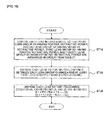
- each lens is disposed in a lens barrel, so that the first lens group having positive refractive power, the second lens group having negative refractive power, the third lens group having positive refractive power, and the fourth lens group having positive refractive power are arranged in order from the object (step ST 10 ).
- each lens is disposed so that, upon zooming from the wide-angle end state to the telephoto end state, the distance between the first lens group and the second lens group changes, the distance between the second lens group and the third lens group changes, the distance between the third lens group and the fourth lens group changes, and at least the first lens group G 1 moves (step S 20 ).
- Each lens is disposed in the lens barrel so that the following conditional expressions (3) and (4) are satisfied (step ST 30 ).
- fG1 denotes a focal length of the first lens group G 1
- fG4 denotes a focal length of the fourth lens group G 4
- ft denotes a focal length of the zoom lens ZL in the telephoto end state
- dG1 denotes a thickness of the first lens group G 1 on the optical axis.
- a set of cemented lenses constituted by, in order from the object, a negative meniscus lens L 11 having a convex surface facing the object and a biconvex positive lens L 12 is disposed in the lens barrel.
- each lens is disposed in the lens barrel so that a biconcave negative lens L 21 , a biconcave negative lens L 22 and a positive meniscus lens L 23 having a convex surface facing the object are disposed in order from the object.
- each lens is disposed in the lens barrel so that a biconvex positive lens L 31 and a negative meniscus lens L 32 having a convex surface facing the object are disposed in order from the object.
- a biconvex positive lens L 41 is disposed in the lens barrel.
- Each lens is disposed in the lens barrel so that the above mentioned conditional expressions (3) and (4) are satisfied (the correspondence value of the conditional expression (3) is 0.881, and the correspondence value of the conditional expression (4) is 12.471).
- a compact zoom lens with high variable power can be manufactured.
- Table 1 to Table 4 are data tables of Example 1 to Example 4 respectively.
- each reference symbol in FIG. 1 which corresponds to Example 1, is independently used from the other examples. Therefore even if a reference symbol is the same as a reference symbol of another example, this does not means that configurations thereof are the same.
- the C-line (wavelength: 656.2730 nm), the d-line (wavelength: 587.5620 nm), the F-line (wavelength: 486.1330 nm) and the g-line (wavelength: 435.8350 nm) are used to calculate aberration characteristics.
- the surface number indicates a sequential number assigned to the optical surface counted from the object side along the light traveling direction
- R indicates a radius of curvature of each optical surface
- D indicates a surface distance which is a distance from each optical surface to the next optical surface (or image plane) on the optical axis
- nd indicates a refractive index of the material of the optical member at d-line
- ⁇ d indicates an Abbe number of the material of the optical member based on d-line.
- the object plane indicates a surface of the object
- (Variable) indicates a variable surface distance
- “ ⁇ ” of the radius of curvature indicates a plane or an aperture
- stop S indicates an aperture stop S
- the image plane indicates an image plane I.
- the refractive index of air “1.00000” is omitted. If the optical surface is aspherical, a paraxial radius of curvature is shown in the column of the radius of curvature R.
- f indicates a focal length of the zoom lens
- FNo indicates an F number
- ⁇ indicates a half angle of view (maximum incident angle, unit: °)
- Y indicates an image height
- Bf indicates a distance on the optical axis from the last surface of the lens to the paraxial image plane
- Bf air equivalent
- TL indicates a total length of the zoom lens (Bf is added to the distance on the optical axis from the front surface of the lens to the last surface of the lens)
- WL indicates the total lens length in the wide-angle end state
- TL indicates the total lens length in the telephoto end state.
- Di indicates a value of variable distance in each of the wide-angle end state, the intermediate focal length state (intermediate position 1 is on the wide-angle end side, and intermediate position 2 is on the telephoto end side), and the telephoto end state.
- Di is a variable distance between the i-th surface and the (i+1)th surface.
- G indicates a group number
- First surface of group indicates a surface number of the surface closest to the object in each group
- Group focal length indicates a focal length of each group
- “Lens configuration length” indicates a distance on the optical axis from the lens surface closest to the object to the lens surface closest to the image in each group.
- mm is normally used as the unit of focal length f, radius of curvature R, surface distance D and other lengths, unless otherwise specified, but unit is not limited to “mm”, and another appropriate unit may be used since an equivalent optical performance is acquired even if the zoom lens is proportionally expanded or proportionally reduced.
- Example 1 will be described with reference to FIG. 1 to FIG. 3 and Table 1.
- a zoom lens ZL (ZL 1 ) according to Example 1 is constituted by, in order from an object, a first lens group G 1 having positive refractive power, a second lens group G 2 having negative refractive power, an aperture stop S for adjusting quantity of light, a third lens group G 3 having positive refractive power, and a fourth lens group G 4 having positive refractive power.
- the first lens group G 1 is constituted by a cemented lens of a negative meniscus lens L 11 having a convex surface facing the object and a biconvex positive lens L 12 disposed in order from the object.
- the second lens group G 2 is constituted by, in order from the object, a biconcave negative lens L 21 , a biconcave negative lens L 22 , and a positive meniscus lens L 23 having a convex surface facing the object.
- the third lens group G 3 is constituted by, in order from the object, a biconvex positive lens L 31 and a negative meniscus lens L 32 having a convex surface facing the object.
- the fourth lens group G 4 is constituted by a biconvex positive lens L 41 .
- a glass block GB constituted by a low-pass filter, an infrared cut-off filter or the like, to cut off a spatial frequency exceeding the critical resolution of the solid-state image sensor (e.g CCD disposed on the image plane I), and a sensor cover glass CG of the solid-state image sensor, are disposed.
- the zoom lens ZL 1 upon zooming from the wide-angle end state to the telephoto end state, a distance between the first lens group and the second lens group changes, a distance between the second lens group and the third lens group changes, a distance between the third lens group and the fourth lens group changes, and all of the first lens group G 1 to the fourth lens group G 4 move.
- the first lens group G 1 moves toward the image first and then moves toward the object.
- the second lens group G 2 moves toward the image first and then moves toward the object.
- the third lens group G 3 moves toward the object.
- the fourth lens group G 4 moves toward the object first and then moves toward the image.
- the aperture stop S moves toward the object together with the third lens group G 3 .
- Table 1 shows each data value of Example 1.
- the surface numbers 1 to 20 in Table 1 correspond to each optical surface of m 1 to m 20 shown in FIG. 1 .
- the zoom lens ZL 1 according to this example satisfies the conditional expressions (1) to (5).
- FIG. 2 and FIG. 3 are graphs showing various aberrations (spherical aberration, astigmatism, distortion, coma aberration and lateral chromatic aberration) of the zoom lens according to Example 1.
- FIG. 2( a ) is a set of graphs showing various aberrations of this example upon focusing on infinity in the wide-angle end state
- FIG. 2( b ) is a set of graphs showing various aberrations of this example upon focusing on infinity in the intermediate focal length state on the wide-angle end side (intermediate position 1 )
- FIG. 3( a ) is a set of graphs showing various aberrations of this example upon focusing on infinity in the intermediate focal length state on the telephoto end side (intermediate position 2 )
- FIG. 3( b ) is a set of graphs showing various aberrations of this example upon focusing on infinity in the telephoto end state.
- FNO indicates an F number
- Y indicates an image height
- d indicates aberration at d-line
- g indicates aberration at g-line
- C indicates aberration at C-line
- F indicates aberration at F-line.
- No indication refers to an aberration at d-line.
- the solid line indicates the sagittal image plane
- the broken line indicates the meridional image plane.
- the zoom lens ZL 1 according to Example 1 has an excellent optical performance, where various aberrations are corrected well.
- Example 2 will be described with reference to FIG. 4 to FIG. 6 and Table 2.
- a zoom lens ZL (ZL 2 ) according to Example 2 is constituted by, in order from an object, a first lens group G 1 having positive refractive power, a second lens group G 2 having negative refractive power, an aperture stop S for adjusting quantity of light, a third lens group G 3 having positive refractive power, and a fourth lens group G 4 having positive refractive power.
- the first lens group G 1 is constituted by a cemented lens of a negative meniscus lens L 11 having a convex surface facing the object and a biconvex positive lens L 12 disposed in order from the object.
- the second lens group G 2 is constituted by, in order from the object, a biconcave negative lens L 21 , a biconcave negative lens L 22 , and a positive meniscus lens L 23 having a convex surface facing the object.
- the third lens group G 3 is constituted by, in order from the object, a biconvex positive lens L 31 and a negative meniscus lens L 32 having a convex surface facing the object.
- the fourth lens group G 4 is constituted by a biconvex positive lens L 41 .
- a glass block GB constituted by a low-pass filter, an infrared cut-off filter or the like, to cut off a spatial frequency exceeding the critical resolution of the solid-state image sensor (e.g CCD disposed on image plane I), and a sensor cover glass CG of the solid-state image sensor, are disposed.
- the zoom lens ZL 2 upon zooming from the wide-angle end state to the telephoto end state, a distance between the first lens group and the second lens group changes, a distance between the second lens group and the third lens group changes, a distance between the third lens group and the fourth lens group changes, and all of the first lens group G 1 to the fourth lens group G 4 move.
- the first lens group G 1 moves toward the image first and then moves toward the object.
- the second lens group G 2 moves toward the image first and then moves toward the object.
- the third lens group G 3 moves toward the object.
- the fourth lens group G 4 moves toward the object first and then moves toward the image.
- the aperture stop S moves toward the object together with the third lens group G 3 .
- Table 2 shows each data value of Example 2.
- the surface numbers 1 to 20 in Table 2 correspond to each optical surface of m 1 to m 20 shown in FIG. 4 .
- the zoom lens ZL 2 according to this example satisfies the conditional expressions (1) to (5).
- FIG. 5 and FIG. 6 are graphs showing various aberrations (spherical aberration, astigmatism, distortion, coma aberration and lateral chromatic aberration) of the zoom lens according to Example 2.
- FIG. 5( a ) is a set of graphs showing various aberrations of this example upon focusing on infinity in the wide-angle end state
- FIG. 5( b ) is a set of graphs showing various aberrations of this example upon focusing on infinity in the intermediate focal length state on the wide-angle end side (intermediate position 1 )
- FIG. 6( a ) is a set of graphs showing various aberrations of this example upon focusing on infinity in the intermediate focal length state on the telephoto end side (intermediate position 2 )
- FIG. 6( b ) is a set of graphs showing various aberrations of this example upon focusing on infinity in the telephoto end state.
- the zoom lens ZL 2 according to Example 2 has an excellent optical performance, where various aberrations are corrected well.
- Example 3 will be described with reference to FIG. 7 to FIG. 9 and Table 3.
- a zoom lens ZL (ZL 3 ) according to Example 3 is constituted by, in order from an object, a first lens group G 1 having positive refractive power, a second lens group G 2 having negative refractive power, an aperture stop S for adjusting quantity of light, a third lens group G 3 having positive refractive power, and a fourth lens group G 4 having positive refractive power.
- the first lens group G 1 is constituted by a cemented lens of a negative meniscus lens L 11 having a convex surface facing the object, and a biconvex positive lens L 12 disposed in order from the object.
- the second lens group G 2 is constituted by, in order from the object, a biconcave negative lens L 21 , a biconcave negative lens L 22 , and a positive meniscus lens L 23 having a convex surface facing the object.
- the third lens group G 3 is constituted by, in order from the object, a biconvex positive lens L 31 and a negative meniscus lens L 32 having a convex surface facing the object.
- the fourth lens group G 4 is constituted by a biconvex positive lens L 41 .
- a glass block GB constituted by a low-pass filter, an infrared cut-off filter or the like, to cut off a spatial frequency exceeding the critical resolution of the solid-state image sensor (e.g CCD disposed on image plane I), and a sensor cover glass CG of the solid-state image sensor, are disposed.
- the zoom lens ZL 3 upon zooming from the wide-angle end state to the telephoto end state, a distance between the first lens group and the second lens group changes, a distance between the second lens group and the third lens group changes, a distance between the third lens group and the fourth lens group changes, and all of the first lens group G 1 to the fourth lens group G 4 move.
- the first lens group G 1 moves toward the image first and then moves toward the object.
- the second lens group G 2 moves toward the image first and then moves toward the object.
- the third lens group G 3 moves toward the object.
- the fourth lens group G 4 moves toward the object first and then moves toward the image.
- the aperture stop S moves toward the object together with the third lens group G 3 .
- Table 3 shows each data value of Example 3.
- the surface numbers 1 to 20 in Table 3 correspond to each optical surface of m 1 to m 20 shown in FIG. 7 .
- the zoom lens ZL 3 according to this example satisfies the conditional expressions (1) to (5).
- FIG. 8 and FIG. 9 are graphs showing various aberrations (spherical aberration, astigmatism, distortion, coma aberration and lateral chromatic aberration) of the zoom lens according to Example 3.
- FIG. 8( a ) is a set of graphs showing various aberrations of this example upon focusing on infinity in the wide-angle end state
- FIG. 8( b ) is a set of graphs showing various aberrations of this example upon focusing on infinity in the intermediate focal length state on the wide-angle end side (intermediate position 1 )
- FIG. 9( a ) is a set of graphs showing various aberrations of this example upon focusing on infinity in the intermediate focal length state on the telephoto end side (intermediate position 2 )
- FIG. 9( b ) is a set of graphs showing various aberrations of this example upon focusing on infinity in the telephoto end state.
- the zoom lens ZL 3 according to Example 3 has an excellent optical performance, where various aberrations are corrected well.
- Example 4 will be described with reference to FIG. 10 to FIG. 12 and Table 4.
- a zoom lens ZL (ZL 4 ) according to Example 4 is constituted by, in order from an object, a first lens group G 1 having positive refractive power, a second lens group G 2 having negative refractive power, an aperture stop S for adjusting quantity of light, a third lens group G 3 having positive refractive power, and a fourth lens group G 4 having positive refractive power.
- the first lens group G 1 is constituted by a cemented lens of a negative meniscus lens L 11 having a convex surface facing the object and a biconvex positive lens L 12 disposed in order from the object.
- the second lens group G 2 is constituted by, in order from the object, a biconcave negative lens L 21 , a biconcave negative lens L 22 , and a positive meniscus lens L 23 having a convex surface facing the object.
- the third lens group G 3 is constituted by, in order from the object, a biconvex positive lens L 31 and a biconcave negative lens L 32 .
- the fourth lens group G 4 is constituted by a biconvex positive lens L 41 .
- a glass block GB constituted by a low-pass filter, an infrared cut-off filter or the like, to cut off a spatial frequency exceeding the critical resolution of the solid-state image sensor (e.g CCD disposed on image plane I), and a sensor cover glass CG of the solid-state image sensor, are disposed.
- the zoom lens ZL 4 upon zooming from the wide-angle end state to the telephoto end state, a distance between the first lens group and the second lens group changes, a distance between the second lens group and the third lens group changes, a distance between the third lens group and the fourth lens group changes, and all of the first lens group G 1 to the fourth lens group G 4 move.
- the first lens group G 1 moves toward the image first and then moves toward the object.
- the second lens group G 2 moves toward the image first and then moves toward the object.
- the third lens group G 3 moves toward the object.
- the fourth lens group G 4 moves toward the object first and then moves toward the image.
- the aperture stop S moves toward the object together with the third lens group G 3 .
- Table 4 shows each data value of Example 4.
- the surface numbers 1 to 20 in Table 4 correspond to each optical surface of m 1 to m 20 shown in FIG. 10 .
- the zoom lens ZL 4 according to this example satisfies the conditional expressions (1) to (5).
- FIG. 11 and FIG. 12 are graphs showing various aberrations (spherical aberration, astigmatism, distortion, coma aberration and lateral chromatic aberration) of the zoom lens according to Example 4.
- FIG. 11( a ) is a set of graphs showing various aberrations of this example upon focusing on infinity in the wide-angle end state
- FIG. 11( b ) is a set of graphs showing various aberrations of this example upon focusing on infinity in the intermediate focal length state on the wide-angle end side (intermediate position 1 )
- FIG. 12( a ) is a set of graphs showing various aberrations of this example upon focusing on infinity in the intermediate focal length state on the telephoto end side (intermediate position 2 )
- FIG. 12( b ) is a set of graphs showing various aberrations of this example upon focusing on infinity in the telephoto end state.
- the zoom lens ZL 4 according to Example 4 has an excellent optical performance, where various aberrations are corrected well.
- a compact zoom lens having high variable power can be implemented.
- the zoom lens constituted by four lens groups was shown, but the present invention can also be applied to a zoom lens constituted by a different number of lens groups, such as five or six lens groups.
- a lens or a lens group may be added to the configuration on the side closest to the object, or a lens or a lens group may be added to the configuration on the side closest to the image.
- “Lens group” refers to a portion having at least one lens isolated by an air distance which changes upon zooming.
- a single or plurality of lens group(s) or a partial lens group may be designed to be a focusing lens group, which performs focusing from an object at infinity to an object at a close distance by moving in the optical axis direction.
- This focusing lens group can be applied to auto focus, and is also suitable for driving a motor for auto focusing (driving using an ultrasonic motor or the like). It is particularly preferable that at least a part of the fourth lens group G 4 is designed to be the focusing lens group.
- a lens group or a partial lens group may be designed to be a vibration-isolating lens group, which corrects image blurs generated by camera shake, by moving the lens group or the partial lens group in a direction orthogonal to the optical axis or rotating (oscillating) the lens group or the partial lens group in an in-plane direction that includes the optical axis. It is particularly preferable that at least a part of the third lens group G 3 is designed to be the vibration-isolating lens group.
- the lens surface may be formed to be a spherical surface or a plane, or an aspherical surface. If the lens surface is a spherical surface or a plane, lens processing, assembly and adjustment are easy, and deterioration of optical performance, due to an error generated in processing, assembly or adjustment can be prevented. Even if the image plane is shifted, the drawing performance is not affected very much, which is desirable.
- the aspherical surface can be any aspherical surface out of an aspherical surface generated by grinding, a glass-molded aspherical surface generated by forming glass in an aspherical shape using a die, and a composite aspherical surface generated by forming resin on the surface of the glass to be an aspherical shape.
- the lens surface may be a diffraction surface, and the lens may be a refractive index-distributed lens (GRIN lens) or a plastic lens.
- GRIN lens refractive index-distributed lens
- the aperture stop is disposed near the third lens group G 3 , but the role of the aperture stop may be substituted by a frame of the lens, without disposing a separate member as the aperture stop.
- Each lens surface may be coated with an anti-reflection film, which has high transmittance in a wide wavelength region in order to decrease flares and ghosts, and implement high optical performance with high contrast.
- a zoom lens ZL according to Embodiment 3 has, in order from an object: a first lens group G 1 having positive refractive power; a second lens group G 2 having negative refractive power; a third lens group G 3 having positive refractive power; and a fourth lens group G 4 having positive refractive power.
- a distance between the first lens group G 1 and the second lens group G 2 changes, a distance between the second lens group G 2 and the third lens group G 3 changes, and a distance between the third lens group G 3 and the fourth lens group G 4 changes.
- the first lens group, the second lens group, the third lens group, and the fourth lens group move upon zooming from the wide-angle end state to the telephoto end state, whereby various aberrations generated due to the high variable power can be corrected well.
- the first lens group G 1 is constituted by, in order from the object, a lens having negative refractive power, and a lens having positive refractive power.
- the second lens group G 2 is constituted by, in order from the object, a lens having negative refractive power, a lens having negative refractive power, and a lens having positive refractive power.
- a number of lenses constituting the second lens group G 2 is small, which is effective to make the zoom lens lighter and can decrease thickness of the zoom lens in the retracted state.
- ⁇ D2 denotes a distance on the optical axis from the lens surface closest to the object to the lens surface closest to the image in the second lens group G 2
- ft denotes a focal length of the zoom lens ZL in the telephoto end state.
- the conditional expression (6) specifies an appropriate range of the thickness of the second lens group G 2 on the optical axis. If the lower limit value of the conditional expression (6) is not reached, it becomes difficult to correct curvature of field and coma aberration in the wide-angle end state, which is not desirable. To demonstrate the effect of the invention with certainty, the lower limit value of the conditional expression (6) is preferable 0.065. To demonstrate the effect of the invention with higher certainty, the lower limit value of the conditional expression (6) is preferably 0.080. If the upper limit value of the conditional expression (6) is exceeded, on the other hand, it becomes difficult to correct curvature of field. Moreover, thickness of the zoom lens in the retracted state increases, which is not desirable.
- the upper limit value of the conditional expression (6) is preferably 0.113.
- the upper limit value of the conditional expression (6) is preferably 0.110.
- the conditional expression (7) specifies an appropriate range of the ratio between the focal length of the fourth lens group G 4 and the focal length of the zoom lens ZL in the wide-angle end state. If the lower limit value of the conditional expression (7) is not reached, it becomes difficult to correct curvature of field, which is not desirable.
- the lower limit value of the conditional expression (7) is preferably 4.6.
- the lower limit value of the conditional expression (7) is preferably 5.0. If the upper limit value of the conditional expression (7) is exceeded, on the other hand, it becomes difficult to correct curvature of field, which is not desirable.
- the upper limit value of the conditional expression (7) is preferably 6.4.
- the upper limit value of the conditional expression (7) is preferably 5.9.
- the third lens group G 3 is constituted by one single lens having positive refractive power and one single lens having negative refractive power.
- TLt denotes a total length of the optical system of the zoom lens ZL in the telephoto end state
- ft denotes a focal length of the zoom lens ZL in the telephoto end state
- the conditional expression (8) specifies an appropriate range of the total length of the optical system in the telephoto end state and the focal length of the zoom lens ZL in the telephoto end state. If the lower limit value of the conditional expression (8) is not reached, it becomes difficult to correct curvature of field and astigmatism, which is not desirable.
- the lower limit value of the conditional expression (8) is preferably 0.80.
- the lower limit value of the conditional expression (8) is preferably 1.20. If the upper limit value of the conditional expression (8) is exceeded, on the other hand, it becomes difficult to correct spherical aberration and lateral chromatic aberration in the telephoto end state, which is not desirable.
- the total length of the optical system increases, which is not desirable.
- the upper limit value of the conditional expression (8) is preferably 1.35.
- the upper limit value of the conditional expression (8) is preferably 1.30.
- conditional expression (9) specifies an appropriate range of the focal length of the second lens group G 2 and the focal length of the first lens group G 1 .
- the lower limit value of the conditional expression (9) is preferably 0.18.
- the lower limit value of the conditional expression (9) is preferably 0.20.
- the upper limit value of the conditional expression (9) is preferably 0.30.
- the upper limit value of the conditional expression (9) is 0.22.
- the conditional expression (10) specifies an appropriate range of the focal length of the first lens group G 1 . If the lower limit value of the conditional expression (10) is not reached, it becomes difficult to correct curvature of field and astigmatism, which is not desirable. To demonstrate the effect of the invention with certainty, the lower limit value of the conditional expression (10) is preferably 0.75. To demonstrate the effect of the invention with higher certainty, the lower limit value of the conditional expression (10) is preferably 0.85. If the upper limit value of the conditional expression (10) is exceeded, on the other hand, it becomes difficult to correct spherical aberration and lateral chromatic aberration in the telephoto end state, which is not desirable.
- the upper limit value of the conditional expression (10) is preferably 1.25.
- the upper limit value of the conditional expression (10) is preferably 1.10.
- the lens having negative refractive power and the lens having positive refractive power constituting the first lens group are cemented. If these lenses are cemented lenses, chromatic aberration can be corrected better.
- the lens having negative refractive power, the lens having negative refractive power, and the lens having positive refractive power, which constitute the second lens group G 2 are separated from each other by an air distance.
- the fourth lens group G 4 is constituted by one single lens having positive refractive power.
- the fourth lens group G 4 may be constituted by one cemented lens having positive refractive power.
- the image side lens surface of the lens having positive refractive power, which constitutes the first lens group G 1 is formed in an aspherical shape. If the image side lens surface of the lens having positive refractive power, which constitutes the first lens group G 1 , is aspherical, spherical aberration in the telephoto end state can be corrected well.
- At least one of lens surfaces of the lenses having negative refractive power, which constitute the second lens group G 2 is formed in an aspherical shape. If at least one of the surfaces of the lenses having negative refractive power, which constitute the second lens group G 2 , is aspherical, curvature of field and astigmatism can be corrected well.
- At least one of the surfaces of the lenses, which constitute the third lens group G 3 is formed in an aspherical shape. If at least one of the surfaces of the lenses, which constitute the third lens group G 3 , is aspherical, aspherical aberration and coma aberration can be corrected well.
- At least one of the surfaces of the lenses, which constitute the fourth lens group G 4 is formed in an aspherical shape. If at least one of the surfaces of the lenses, which constitute the fourth lens group G 4 , is aspherical, curvature of field and astigmatism can be corrected well.
- a medium of the lenses constituting the fourth lens group G 4 is plastic resin.
- the fourth lens group G 4 moves along the optical axis. If the fourth lens group G 4 is used for focusing, fluctuation of curvature of field and astigmatism upon focusing on an object at a finite distance can be decreased.
- This camera 1 is an interchangeable lens type mirrorless camera that includes the zoom lens ZL according to Embodiment 3 as a photographing lens 2 .
- lights from an object are collected by the photographing lens 2 , and form an object image on an image plane of an imaging unit 3 via an OLPF (Optical Low pass filter), which is not illustrated.
- OLPF Optical Low pass filter
- the object image is photoelectrically-converted by a photoelectric conversion element disposed in the imaging unit 3 , whereby the image of the object is generated.
- This image is displayed on an EVF (Electronic View Finder) 4 disposed in the camera 1 . Thereby the user can view the object via the EVF 4 .
- EVF Electronic View Finder
- the photoelectrically-converted image is stored in memory (not illustrated) by the imaging unit 3 .
- the user can photograph the image of the object using this camera 1 .
- an example of the mirrorless camera was described, but an effect similar to the case of this camera 1 can be demonstrated even when the zoom lens ZL according to Embodiment 3 is included in a single lens reflex type camera, which has a quick return mirror in the camera main unit, and views the object using a finder optical system.
- the zoom lens ZL constituted by four lens groups was shown, but the present invention can also be applied to a zoom lens constituted by a different number of lens groups, such as five or six lens groups.
- a lens or a lens group may be added to the configuration on the side closest to the object, or a lens or a lens group may be added to the configuration on the side closest to the image.
- “Lens group” refers to a portion having at least one lens isolated by an air distance which changes upon zooming.
- a single or plurality of lens group(s) or a partial lens group may be designed to be a focusing lens group, which performs focusing from an object at infinity to an object at a close distance by moving in the optical axis direction.
- This focusing lens group can be applied to auto focus, and is also suitable for driving a motor for auto focusing (driving using an ultrasonic motor or the like). It is particularly preferable that at least a part of the fourth lens group G 4 is designed to be the focusing lens group.
- a lens group or a partial lens group may be designed to be a vibration-isolating lens group, which corrects image blurs generated by camera shake, by moving the lens group or the partial lens group in a direction orthogonal to the optical axis or rotating (oscillating) the lens group or the partial lens group in an in-plane direction that includes the optical axis. It is particularly preferable that at least a part of the third lens group G 3 is designed to be the vibration-isolating lens group.
- the lens surface may be formed to be a spherical surface or a plane, or an aspherical surface. If the lens surface is a spherical surface or a plane, lens processing, assembly and adjustment are easy, and deterioration of optical performance, due to an error generated in processing, assembly or adjustment can be prevented. Even if the image plane is shifted, the drawing performance is not affected very much, which is desirable.
- the aspherical surface can be any aspherical surface out of an aspherical surface generated by grinding, a glass-molded aspherical surface generated by forming glass in an aspherical shape using a die, and a composite aspherical surface generated by forming resin on the surface of the glass to be an aspherical shape.
- the lens surface may be a diffraction surface, and the lens may be a refractive index-distributed lens (GRIN lens) or a plastic lens.
- GRIN lens refractive index-distributed lens
- the aperture stop S is disposed near the third lens group G 3 , but the role of the aperture stop may be substituted by a frame of the lens, without disposing a separate member as the aperture stop.
- Each lens surface may be coated with an anti-reflection film, which has high transmittance in a wide wavelength region in order to decrease flares and ghosts, and implement high optical performance with high contrast.
- the zoom ratio of the zoom lens ZL of Embodiment 3 is about 7 to 8.
- each lens is disposed to prepare the first to fourth lens group G 1 to G 4 respectively (step S 100 ).
- Each lens group is disposed so that upon zooming from the wide-angle end state to the telephoto end state, the distance between the first lens group G 1 and the second lens group G 2 changes, the distance between the second lens group G 2 and the third lens group G 3 changes, and the distance between the third lens group G 3 and the fourth lens group G 4 changes (step S 200 ).
- a lens having negative refractive power and a lens having positive refractive power are disposed in order from the object (step S 300 ).
- a lens having negative refractive power, a lens having negative refractive power, and a lens having positive refractive power are disposed in order from the object (step S 400 ).
- Each lens group is disposed so that the above mentioned conditional expressions (6) and (7) are satisfied (step S 500 ).
- the first lens group G 1 is prepared by disposing a cemented lens where a negative meniscus lens L 11 having a convex surface facing the object and a positive lens L 12 of which image side surface is aspherical, are cemented in order from the object.
- the second lens group G 2 is prepared by disposing: a biconcave negative lens L 21 ; a negative lens L 22 of which object side surface and image side surface are aspherical; and a positive meniscus lens L 23 having a convex surface facing the object.
- the third lens group G 3 is prepared by disposing: a positive lens L 31 of which object side surface and image side surface are aspherical; and a negative lens L 32 of which image side surface is aspherical.
- the fourth lens group G 4 is prepared by disposing a positive lens L 41 of which object side surface and image side surfaced are aspherical. Each lens group prepared like this is disposed according to the above mentioned procedure, whereby the zoom lens ZL is manufactured.
- a zoom lens ZL according to Embodiment 4 has, in order from an object: a first lens group G 1 having positive refractive power; a second lens group G 2 having negative refractive power; a third lens group G 3 having positive refractive power; and a fourth lens group G 4 having positive refractive power.
- this zoom lens ZL upon zooming from a wide-angle end state to a telephoto end state, a distance between the first lens group G 1 and the second lens group G 2 changes, a distance between the second lens group G 2 and the third lens group G 3 changes, and a distance between the third lens group G 3 and the fourth lens group G 4 changes.
- the first lens group, the second lens group, the third lens group, and the fourth lens group move upon zooming from the wide-angle end state to the telephoto end state, whereby various aberrations generated due to the high variable power can be corrected well.
- the first lens group G 1 is constituted by, in order from the object, a lens having negative refractive power, and a lens having positive refractive power.
- a number of lenses constituting the first lens group G 1 is small, which is effective to make the zoom lens lighter, and can decrease thickness of the zoom lens in the retracted state.
- the zoom lens ZL according to Embodiment 4 it is preferable that the following conditional expression (11) is satisfied. ⁇ 0.25 ⁇ M 2/ fw ⁇ 1.10 (11) where M2 denotes a moving distance of the second lens group G 2 upon zooming from the wide-angle end state to the telephoto end state (where a direction toward an image plane is positive), and fw denotes a focal length of the zoom lens ZL in the wide-angle end state.
- the conditional expression (11) specifies an appropriate range of the moving distance of the second lens group G 2 upon zooming from the wide-angle end state to the telephoto end state. If the lower limit value of the conditional expression (11) is not reached, it becomes difficult to correct curvature of field, which is not desirable. To demonstrate the effect of the invention with certainty, the lower limit value of the conditional expression (11) is preferable ⁇ 0.21. To demonstrate the effect of the invention with higher certainty, the lower limit value of the conditional expression (11) is ⁇ 0.17. If the upper limit value of the conditional expression (11) is exceeded, it becomes difficult to correct curvature of field, which is not desirable. Moreover, the moving distance of the second lens group G 2 increases and thickness of the zoom lens in the retracted state increases, which is not desirable.
- the upper limit value of the conditional expression (11) is preferably 0.93.
- the upper limit value of the conditional expression (11) is preferably 0.10.
- the conditional expression (12) specifies an appropriate range of the ratio between the focal length of the lens having positive refractive power included in the first lens group G 1 and the focal length of the zoom lens ZL in the wide-angle end state. If the lower limit value of the conditional expression (12) is not reached, it becomes difficult to correct chromatic aberration, which is not desirable. Moreover, because of the increase in refractive power of the positive lens in the first lens group G 1 , the edge thickness of this positive lens becomes thinner, which makes manufacturing difficult. This means that the center thickness of the lens must be increased to secure an appropriate edge thickness, and in this case, the thickness of the zoom lens in the retracted state increases, which is not desirable.
- the lower limit value of the conditional expression (12) is preferably 3.2.
- the lower limit value of the conditional expression (12) is preferably 3.5. If the upper limit value of the conditional expression (12) is exceeded, on the other hand, it becomes difficult to correct chromatic aberration, which is not desirable.
- the upper limit value of the conditional expression (12) is preferably 4.2.
- the upper limit value of the conditional expression (12) is preferably 3.8.
- the third lens group G 3 is constituted by one single lens having positive refractive power and one single lens having negative refractive power.
- the third lens group G 3 includes a lens having negative refractive power, and the following conditional expression (13) is satisfied. ⁇ 4.5 ⁇ ( R 72+ R 71)/( R 72 ⁇ R 71) ⁇ 0.1 (13) where R71 denotes a radius of curvature of the object side lens surface of the lens having negative refractive power included in the third lens group G 3 , and R72 denotes a radius of curvature of the image side lens surface of the lens having negative refractive power included in the third lens group G 3 .
- the conditional expression (13) specifies an appropriate range of the shape of the lens having negative refractive power which is included in the third lens group G 3 . If the lower limit value of the conditional expression (13) is not reached, it becomes difficult to correct spherical aberration and coma aberration, which is not desirable.
- the lower limit value of the conditional expression (13) is preferably ⁇ 3.8.
- the lower limit value of the conditional expression (13) is preferably ⁇ 2.0.
- the upper limit value of the conditional expression (13) is preferably ⁇ 0.3.
- the upper limit value of the conditional expression (13) is preferably ⁇ 0.5.
- TLt denotes a total length of the optical system of the zoom lens ZL in the telephoto end state
- ft denotes a focal length of the zoom lens ZL in the telephoto end state
- the conditional expression (14) specifies an appropriate range of the total length of the optical system in the telephoto end state and the focal length of the zoom lens ZL in the telephoto end state. If the lower limit value of the conditional expression (14) is not reached, it becomes difficult to correct curvature of field and astigmatism, which is not desirable.
- the lower limit value of the conditional expression (14) is preferably 0.80.
- the lower limit value of the conditional expression (14) is preferably 1.20. If the upper limit value of the conditional expression (14) is exceeded, on the other hand, it becomes difficult to correct spherical aberration and lateral chromatic aberration in the telephoto end state, which is not desirable.
- the total length of the optical system increases, which is not desirable.
- the upper limit value of the conditional expression (14) is preferably 1.35.
- the upper limit value of the conditional expression (14) is preferably 1.30.
- conditional expression (15) specifies an appropriate range of the focal length of the second lens group G 2 and the focal length of the first lens group G 1 .
- the lower limit value of the conditional expression (15) is preferably 0.18.
- the lower limit value of the conditional expression (15) is preferably 0.20.
- the upper limit value of the conditional expression (15) is preferably 0.30.
- the upper limit value of the conditional expression (15) is 0.22.
- the conditional expression (16) specifies an appropriate range of the focal length of the first lens group G 1 . If the lower limit value of the conditional expression (16) is not reached, it becomes difficult to correct curvature of field and astigmatism, which is not desirable. To demonstrate the effect of the invention with certainty, the lower limit value of the conditional expression (16) is preferably 0.75. To demonstrate the effect of the invention with higher certainty, the lower limit value of the conditional expression (16) is preferably 0.85. If the upper limit value of the conditional expression (16) is exceeded, on the other hand, it becomes difficult to correct spherical aberration and lateral chromatic aberration in the telephoto end state, which is not desirable.
- the upper limit value of the conditional expression (16) is preferably 1.25.
- the upper limit value of the conditional expression (16) is preferably 1.10.
- the zoom lens ZL according to Embodiment 4 it is preferable that the following conditional expression (17) is satisfied. 4.0 ⁇ f 1/ fw ⁇ 6.5 (17) where f1 denotes a focal length of the first lens group G 1 , and fw denotes a focal length of the zoom lens ZL in the wide-angle end state.
- the conditional expression (17) specifies an appropriate range of the ratio between the focal length of the first lens group G 1 and the focal length of the zoom lens ZL in the wide-angle end state. If the lower limit value of the conditional expression (17) is not reached, it becomes difficult to correct spherical aberration and lateral chromatic aberration in the telephoto end state, which is not desirable.
- the lower limit value of the conditional expression (17) is preferably 4.6.
- the lower limit value of the conditional expression (17) is preferably 5.3. If the upper limit value of the conditional expression (17) is exceeded, on the other hand, it becomes difficult to correct curvature of field and astigmatism, which is not desirable.
- the upper limit value of the conditional expression (17) is preferably 6.2.
- the upper limit value of the conditional expression (17) is preferably 5.9.
- the zoom lens ZL according to Embodiment 4 it is preferable that the following conditional expression (18) is satisfied. ⁇ 0.4 ⁇ M 3/ ft ⁇ 0.05 (18) where M3 denotes a moving distance of the third lens group G 3 upon zooming from the wide-angle end state to the telephoto end state (where the direction toward the image plane is positive), and ft denotes a focal length of the zoom lens ZL in the telephoto end state.
- the conditional expression (18) specifies an appropriate range of the moving distance of the third lens group G 3 upon zooming from the wide-angle end state to the telephoto end state. If the lower limit value of the conditional expression (18) is not reached, it becomes difficult to correct spherical aberration and coma aberration, which is not desirable.
- the lower limit value of the conditional expression (18) is preferably ⁇ 0.34.
- the lower limit value of the conditional expression (18) is ⁇ 0.30. If the upper limit value of the conditional expression (18) is exceeded, on the other hand, it becomes difficult to correct spherical aberration and coma aberration, which is not desirable.
- the moving distance of the third lens group G 3 increases and the thickness of the zoom lens in the retracted state increases, which is not desirable.
- the upper limit value of the conditional expression (18) is preferably ⁇ 0.10.
- the upper limit value of the conditional expression (18) is preferably ⁇ 0.20.
- the second lens group G 2 is constituted by, in order from the object: a lens having negative refractive power; a lens having negative refractive power; and a lens having positive refractive power.
- the conditional expression (19) specifies an appropriate range of the shape of the lens disposed closest to the image in the lenses having negative refractive power constituting the second lens group G 2 . If the lower limit value of the conditional expression (19) is not reached, it becomes difficult to correct curvature of field in the wide-angle end state and spherical aberration in the telephoto end state, which is not desirable.
- the lower limit value of the conditional expression (19) is preferably 1.98.
- the lower limit value of the conditional expression (19) is preferably 2.20.
- the upper limit value of the conditional expression (19) is preferably 3.23.
- the upper limit value of the conditional expression (19) is preferably 3.00.
- the lens having negative refractive power, the lens having negative refractive power, and the lens having positive refractive power, which constitute the second lens group G 2 are separated from each other by an air distance.
- At least one of lens surfaces of the lenses having negative refractive power, which constitute the second lens group G 2 is formed in an aspherical shape. If at least one of the surfaces of the lenses having negative refractive power, which constitute the second lens group G 2 , is aspherical, curvature of field and astigmatism can be corrected well.
- the lens having negative refractive power and the lens having positive refractive power constituting the first lens group are cemented. If these lenses are cemented lenses, chromatic aberration can be corrected better.
- the fourth lens group G 4 is constituted by one single lens having positive refractive power.
- the fourth lens group G 4 may be constituted by one cemented lens having positive refractive power.
- the image side lens surface of the lens having positive refractive power, which constitutes the first lens group G 1 is formed in an aspherical shape. If the image side lens surface of the lens having positive refractive power, which constitutes the first lens group G 1 , is aspherical, spherical aberration in the telephoto end state can be corrected well.
- At least one of the surfaces of the lenses, which constitute the third lens group G 3 is formed in an aspherical shape. If at least one of the surfaces of the lenses, which constitute the third lens group G 3 , is aspherical, spherical aberration and coma aberration can be corrected well.
- At least one of the surfaces of the lenses, which constitute the fourth lens group G 4 is formed in an aspherical shape. If at least one of the surfaces of the lenses, which constitute the fourth lens group G 4 , is aspherical, curvature of field and astigmatism can be corrected well.
- a medium of the lenses constituting the fourth lens group G 4 is plastic resin.
- the fourth lens group G 4 moves along the optical axis. If the fourth lens group G 4 is used for focusing, fluctuation of curvature of field and astigmatism upon focusing on an object at a finite distance can be decreased.
- FIG. 27 shows a camera, which is an optical apparatus including the zoom lens ZL according to Embodiment 4.
- This camera 1 has the same configuration as the camera of Embodiment 3. Therefore description of the configuration thereof is omitted.
- the zoom ratio of the zoom lens ZL of Embodiment 4 is about 7 to 8.
- each lens is disposed to prepare the first to fourth lens group G 1 to G 4 respectively (step S 100 ).
- Each lens group is disposed so that upon zooming from the wide-angle end state to the telephoto end state, the distance between the first lens group G 1 and the second lens group G 2 changes, the distance between the second lens group G 2 and the third lens group G 3 changes, and the distance between the third lens group G 3 and the fourth lens group G 4 changes (step S 200 ).
- a lens having negative refractive power and a lens having positive refractive power are disposed in order from the object (step S 300 ).
- Each lens is disposed so that the above mentioned conditional expressions (11) and (12) are satisfied (step S 400 ).
- the first lens group G 1 is prepared by disposing a cemented lens where a negative meniscus lens L 11 having a convex surface facing the object and a positive lens L 12 of which image side surface is aspherical, are cemented in order from the object.
- the second lens group G 2 is prepared by disposing: a biconcave negative lens L 21 ; a negative lens L 22 of which object side surface and image side surface are aspherical; and a positive meniscus lens L 23 having a convex surface facing the object.
- the third lens group G 3 is prepared by disposing: a positive lens L 31 of which object side surface and image side surface are aspherical; and a negative lens L 32 of which image side surface is aspherical.
- the fourth lens group G 4 is prepared by disposing a positive lens L 41 of which object side surface and image side surfaced are aspherical. Each lens group prepared like this is disposed according to the above mentioned procedure, whereby the zoom lens ZL is manufactured.
- FIG. 17 , FIG. 19 , FIG. 21 , FIG. 23 and FIG. 25 are cross-sectional views depicting a configuration and refractive power allocation of the zoom lens ZL (ZL 1 to ZL 5 ) according to each example.
- Example 7 shown in FIG. 21 corresponds only to Embodiment 3, and the other examples are applicable to both Embodiments 3 and 4.
- an aspherical surface is expressed by the following expression (b), where y denotes a height in the direction orthogonal to the optical axis, S(y) denotes a distance (sag) along the optical axis from the tangential plane at the vertex of each aspherical surface to the position on the aspherical surface at height y, r denotes a radius of curvature (paraxial radius of curvature) of the reference spherical surface, K denotes a conical coefficient, and An denotes an aspherical coefficient at degree n.
- “E-n” indicates “ ⁇ 10 ⁇ n ”.
- A2 which is the aspherical coefficient at degree 2
- A2 which is the aspherical coefficient at degree 2
- “*” is attached at the right side of the surface number if the surface is aspherical.
- FIG. 17 shows a configuration of the zoom lens ZL 1 according to Example 5.
- the zoom lens ZL 1 shown in FIG. 17 is constituted by, in order from an object: a first lens group G 1 having positive refractive power; a second lens group G 2 having negative refractive power; a third lens group G 3 having positive refractive power; and a fourth lens group G 4 having positive refractive power.
- the first lens group G 1 is constituted by a cemented lens of a negative meniscus lens L 11 having a convex surface facing the object and a positive lens L 12 of which image side surface is aspherical, disposed in order from the object.
- the second lens group G 2 is constituted by, in order from the object, a biconcave negative lens L 21 , a negative lens L 22 of which object side surface and image side surface are aspherical, and a positive meniscus lens L 23 having a convex surface facing the object.
- the third lens group G 3 is constituted by, in order from the object, a positive lens L 31 of which object side surface and image side surface are aspherical, and a negative lens L 32 of which image side surface is aspherical.
- the fourth lens group G 4 is constituted by a positive lens L 41 of which object side surface and image side surface are aspherical.
- An aperture stop S is disposed between the second lens group G 2 and the third lens group G 3 .
- a filter group FL including a low-pass filter, infrared filer and the like is disposed between the fourth lens group G 4 and the image plane I.
- the zoom lens ZL 1 upon zooming from the wide-angle end state to the telephoto end state, the first lens group G 1 moves toward the image first and then moves toward the object, the second lens group G 2 moves toward the image first and then moves toward the object, the third lens group G 3 moves toward the object, and the fourth lens group G 4 moves toward the object first and then moves toward the image, whereby the distance between each lens group changes.
- the aperture stop S moves together with the third lens group G 3 .
- Table 5 shows the data values of the zoom lens ZL 1 according to Example 5.
- f indicates a focal length of the zoom lens
- FNO indicates an F number
- 2 ⁇ indicates an angle of view
- Y indicates a maximum image height
- BF indicates back focus
- TL indicates a total length.
- the back focus BF indicates a distance (air equivalent length) on the optical axis from the lens surface closest to the image (surface 12 in FIG. 17 ) to the image plane I upon focusing on infinity.
- the total length TL indicates a distance (air equivalent length) on the optical axis from the lens surface closest to the object (surface 1 in FIG. 17 ) to the image plane I upon focusing on infinity.
- the first column m in [Lens Data] indicates a sequential number assigned to the lens surface (surface number) counted from the object side along the light traveling direction
- the second column r indicates a radius of curvature of each lens surface
- the third column d indicates a distance from each optical surface to the next optical surface on the optical axis (surface distance)
- the radius of curvature ⁇ indicates a plane, and the refractive index of air 1.00000 is omitted.
- the surface numbers 1 to 18 in Table 5 correspond to the numbers 1 to 18 in FIG. 17 .
- [Lens Group Focal Length] indicates the first surface and the focal length of the first to fourth lens groups G 1 to G 4 respectively.
- mm is normally used as a unit of focal length f, radius of curvature r, surface distance d and other lengths, but unit is not limited to “mm”, since an equivalent optical performance is acquired even if an optical system is proportionally expanded or proportionally reduced.
- the description on the symbols and the description on the data tables are the same for the other examples herein below.
- the axial air distance d3 between the first lens group G 1 and the second lens group G 2 , the axial air distance d9 between the second lens group G 2 and the third lens group G 3 (aperture stop S), the axial air distance d14 between the third lens group G 3 and the fourth lens group G 4 , and the axial air distance d16 between the fourth lens group G 4 and the filter group FL change upon zooming, as mentioned above.
- Table 7 shows the variable distance in each focal length state of the wide-angle end state, the intermediate focal length state, and the telephoto end state upon focusing on infinity.
- Table 8 shows each conditional expression correspondence value of the zoom lens ZL 1 according to Example 5.
- ⁇ D2 denotes a distance on the optical axis from the lens surface closest to the object and the lens surface closest to the image in the second lens group G 2
- TLt denotes a total length of the optical system of the zoom lens ZL 1 in the telephoto end state
- ft denotes the focal length of the zoom lens ZL 1 in the telephoto end state
- fw denotes the focal length of the zoom lens ZL 1 in the wide-angle end state
- f1 denotes the focal length of the first lens group G 1
- f2 denotes the focal length of the second lens group G 2
- f4 denotes the focal length of the fourth lens group G 4 .
- M2 denotes the moving distance of the second lens group G 2 from the wide-angle end state to the telephoto end state (where a direction toward an image plane is positive)
- M3 denotes the moving distance of the third lens group G 3 from the wide-angle end state to the telephoto end state (where the direction toward the image plane is positive).
- TLt denotes the total length of the optical system of the zoom lens ZL 1 in the telephoto end state
- ft denotes the focal length of the zoom lens ZL 1 in the telephoto end state
- fw denotes the focal length of the zoom lens ZL 1 in the wide-angle end state
- f1 denotes the focal length of the first lens group G 1
- f2 denotes the focal length of the second lens group G 2
- f4 denotes the focal length of the fourth lens group G 4
- fL2 denotes the focal length of the lens having positive refractive power included in the first lens group G 1
- R51 and R52 denote the radiuses of curvature of the object side and the image side lens surfaces of the lens disposed closest to the image in the second lens group G 2
- R71 and R72 denote the radiuses of curvature of the object side and the image side lens surfaces of the lens having negative refractive power included in the third lens group G 3 respectively.
- the lens having negative refractive power which is disposed closest to the image in the second lens group G 2 , is the negative lens L 22
- the lens having negative refractive power, included in the third lens group G 3 is the negative lens L 32 .
- the zoom lens ZL 1 according to Example 5 satisfies all the conditional expressions (6) to (19).
- FIG. 18 is a set of graphs of the zoom lens ZL 1 according to Example 5, showing spherical aberration, astigmatism, distortion, lateral chromatic aberration and coma aberration upon focusing on infinity in the wide-angle end state, intermediate focal length state, and telephoto end state.
- FNO indicates an F number
- Y indicates an image height.
- a value of the F number corresponding to the maximum aperture is shown
- the maximum value of the image height is shown
- coma aberration a value of each image height is shown.
- the solid line indicates the sagittal image plane
- the broken line indicates the meridional image plane.
- the same reference symbols as this example are also the same for the graphs showing aberrations of the other examples herein below. As these graphs showing various aberrations clarify, various aberrations are corrected well in the zoom lens ZL 1 according to Example 5 throughout the wide-angle end state to the telephoto end state.
- FIG. 19 shows a configuration of the zoom lens ZL 2 according to Example 6.
- the zoom lens ZL 2 shown in FIG. 19 is constituted by, in order from an object: a first lens group G 1 having positive refractive power; a second lens group G 2 having negative refractive power; a third lens group G 3 having positive refractive power; and a fourth lens group G 4 having positive refractive power.
- the first lens group G 1 is constituted by a cemented lens of a negative meniscus lens L 11 having a convex surface facing the object and a positive lens L 12 of which image side surface is aspherical, disposed in order from the object.
- the second lens group G 2 is constituted by, in order from the object, a biconcave negative lens L 21 , a negative lens L 22 of which object side surface and image side surface are aspherical, and a positive meniscus lens L 23 having a convex surface facing the object.
- the third lens group G 3 is constituted by, in order from the object, a positive lens L 31 of which object side surface and image side surface are aspherical, and a negative lens L 32 of which image side surface is aspherical.
- the fourth lens group G 4 is constituted by a positive lens L 41 of which object side surface is aspherical.
- An aperture stoop S is disposed between the second lens group G 2 and the third lens group G 3 .
- a filter group FL including a low-pass filter, infrared filer and the like is disposed between the fourth lens group G 4 and the image plane I.
- the zoom lens ZL 2 upon zooming from the wide-angle end state to the telephoto end state, the first lens group G 1 moves toward the object, the second lens group G 2 moves toward the object first and then moves toward the image, the third lens group G 3 moves toward the object, and the fourth lens group G 4 moves toward the object first and then moves toward the image, whereby the distance between each lens group changes.
- the aperture stop S moves together with the third lens group G 3 .
- Table 9 shows the data values of the zoom lens ZL 2 according to Example 6.
- the surface numbers 1 to 18 in Table 9 correspond to the numbers 1 to 18 in FIG. 19 .
- Table 10 shows aspherical data, that is, the values of the conical coefficient K and each aspherical coefficient A4 to A10.
- the axial air distance d3 between the first lens group G 1 and the second lens group G 2 , the axial air distance d9 between the second lens group G 2 and the third lens group G 3 (aperture stop S), the axial air distance d14 between the third lens group G 3 and the fourth lens group G 4 , and the axial air distance d16 between the fourth lens group G 4 and the filter group FL change upon zooming, as mentioned above.
- Table 11 shows the variable distance in each focal length state of the wide-angle end state, the intermediate focal length state, and the telephoto end state upon focusing on infinity.
- Table 12 shows each conditional expression correspondence value of the zoom lens ZL 2 according to Example 6.
- the zoom lens ZL 2 according to Example 6 satisfies all the conditional expressions (6) to (19).
- FIG. 20 is a set of graphs of the zoom lens ZL 2 according to Example 6, showing spherical aberration, astigmatism, distortion, lateral chromatic aberration and coma aberration upon focusing on infinity in the wide-angle end state, the intermediate focal length state and the telephoto end state.
- the zoom lens ZL 2 according to Example 6 can correct various aberrations well throughout the wide-angle end state to the telephoto end state.
- FIG. 21 shows a configuration of the zoom lens ZL 3 according to Example 7.
- the zoom lens ZL 3 shown in FIG. 21 is constituted by, in order from an object: a first lens group G 1 having positive refractive power; a second lens group G 2 having negative refractive power; a third lens group G 3 having positive refractive power; and a fourth lens group G 4 having positive refractive power.
- Example 7 corresponds only to Embodiment 3, and does not correspond to Embodiment 4.
- the first lens group G 1 is constituted by a cemented lens of a negative meniscus lens L 11 having a convex surface facing the object and a positive lens L 12 of which image side surface is aspherical, disposed in order from the object.
- the second lens group G 2 is constituted by, in order from the object, a biconcave negative lens L 21 , a negative lens L 22 of which object side surface and image side surface are aspherical, and a positive meniscus lens L 23 having a convex surface facing the object.
- the third lens group G 3 is constituted by, in order from the object, a positive lens L 31 of which object side surface and image side surface are aspherical, and a negative lens L 32 of which image side surface is aspherical.
- the fourth lens group G 4 is constituted by a positive lens L 41 of which object side surface is aspherical.
- An aperture stoop S is disposed between the second lens group G 2 and the third lens group G 3 .
- a filter group FL including a low-pass filter, infrared filer and the like is disposed between the fourth lens group G 4 and the image plane I.
- the zoom lens ZL 3 upon zooming from the wide-angle end state to the telephoto end state, the first lens group G 1 moves toward the image first and then moves toward the object, the second lens group G 2 moves toward the image first and then moves toward the object, the third lens group G 3 moves toward the object, and the fourth lens group G 4 moves toward the object first and then moves toward the image, whereby the distance between each lens group changes.
- the aperture stop S moves together with the third lens group G 3 .
- Table 13 shows the data values of the zoom lens ZL 3 according to Example 7.
- the surface numbers 1 to 18 in Table 13 correspond to the numbers 1 to 18 in FIG. 21 .
- Table 14 shows aspherical data, that is, the values of the conical coefficient K and each aspherical coefficient A4 to A10.
- the axial air distance d3 between the first lens group G 1 and the second lens group G 2 , the axial air distance d9 between the second lens group G 2 and the third lens group G 3 (aperture stop S), the axial air distance d14 between the third lens group G 3 and the fourth lens group G 4 , and the axial air distance d16 between the fourth lens group G 4 and the filter group FL change upon zooming, as mentioned above.
- Table 15 shows the variable distance in each focal length state of the wide-angle end state, the intermediate focal length state, and the telephoto end state upon focusing on infinity.
- Table 16 shows each conditional expression correspondence value of the zoom lens ZL 3 according to Example 7.
- this zoom lens ZL 3 according to Example 7 satisfies all the conditional expressions (6) to (10).
- FIG. 22 is a set of graphs of the zoom lens ZL 3 according to Example 7 showing spherical aberration, astigmatism, distortion, lateral chromatic aberration and coma aberration, upon focusing on infinity in the wide-angle end state, the intermediate focal length state and the telephoto end state.
- the zoom lens ZL 3 according to Example 7 can correct various aberrations well throughout the wide-angle end state to the telephoto end state.
- FIG. 23 shows a configuration of the zoom lens ZL 4 according to Example 8.
- the zoom lens ZL 4 shown in FIG. 23 is constituted by, in order from an object: a first lens group G 1 having positive refractive power; a second lens group G 2 having negative refractive power; a third lens group G 3 having positive refractive power; and a fourth lens group G 4 having positive refractive power.
- the first lens group G 1 is constituted by a cemented lens of a negative meniscus lens L 11 having a convex surface facing the object and a positive lens L 12 of which image side surface is aspherical, disposed in order from the object.
- the second lens group G 2 is constituted by, in order from the object, a biconcave negative lens L 21 , a negative lens L 22 of which object side surface and image side surface are aspherical, and a positive meniscus lens L 23 having a convex surface facing the object.
- the third lens group G 3 is constituted by, in order from the object, a positive lens L 31 of which object side surface and image side surface are aspherical, and a negative lens L 32 of which image side surface is aspherical.
- the fourth lens group G 4 is constituted by a positive lens L 41 of which object side surface and image side surface are aspherical.
- An aperture stoop S is disposed between the second lens group G 2 and the third lens group G 3 .
- a filter group FL including a low-pass filter, infrared filer and the like is disposed between the fourth lens group G 4 and the image plane I.
- the zoom lens ZL 4 upon zooming from the wide-angle end state to the telephoto end state, the first lens group G 1 moves toward the image first and then moves toward the object, the second lens group G 2 moves toward the image first and then moves toward the object, the third lens group G 3 moves toward the object, and the fourth lens group G 4 moves toward the object first and then moves toward the image, whereby the distance between each lens group changes.
- the aperture stop S moves together with the third lens group G 3 .
- zoom lens ZL 4 In the zoom lens ZL 4 according to Example 8, focusing from an object at infinity to an object at a close distance is performed by the fourth lens group G 4 moving toward the object.
- Table 17 shows the data values of the zoom lens ZL 4 according to Example 8.
- the surface numbers 1 to 18 in Table 17 correspond to the numbers 1 to 18 in FIG. 23 .
- the axial air distance d3 between the first lens group G 1 and the second lens group G 2 , the axial air distance d9 between the second lens group G 2 and the third lens group G 3 (aperture stop S), the axial air distance d14 between the third lens group G 3 and the fourth lens group G 4 , and the axial air distance d16 between the fourth lens group G 4 and the filter group FL change upon zooming, as mentioned above.
- Table 19 shows the variable distance in each focal length state of the wide-angle end state, the intermediate focal length state, and the telephoto end state upon focusing on infinity.
- Table 20 shows each conditional expression correspondence value of the zoom lens ZL 4 according to Example 8.
- the zoom lens ZL 4 according to Example 8 satisfies all the conditional expressions (6) to (19).
- FIG. 24 is a set of graphs of the zoom lens ZL 4 according to Example 8 showing spherical aberration, astigmatism, distortion, lateral chromatic aberration and coma aberration, upon focusing on infinity in the wide-angle end state, the intermediate focal length state and the telephoto end state.
- the zoom lens ZL 4 according to Example 8 can correct various aberrations well throughout the wide-angle end state to the telephoto end state.
- FIG. 25 shows a configuration of the zoom lens ZL 5 according to Example 9.
- the zoom lens ZL 5 shown in FIG. 25 is constituted by, in order from an object: a first lens group G 1 having positive refractive power; a second lens group G 2 having negative refractive power; a third lens group G 3 having positive refractive power; and a fourth lens group G 4 having positive refractive power.
- the first lens group G 1 is constituted by a cemented lens of a negative meniscus lens L 11 having a convex surface facing the object and a positive lens L 12 of which image side surface is aspherical, disposed in order from the object.
- the second lens group G 2 is constituted by, in order from the object, a biconcave negative lens L 21 , a negative lens L 22 of which object side surface and image side surface are aspherical, and a positive meniscus lens L 23 having a convex surface facing the object.
- the third lens group G 3 is constituted by, in order from the object, a positive lens L 31 of which object side surface and image side surface are aspherical, and a negative lens L 32 of which image side surface is aspherical.
- the fourth lens group G 4 is constituted by a positive lens L 41 of which object side surface is aspherical.
- An aperture stoop S is disposed between the second lens group G 2 and the third lens group G 3 .
- a filter group FL including a low-pass filter, infrared filer and the like is disposed between the fourth lens group G 4 and the image plane I.
- the zoom lens ZL 5 upon zooming from the wide-angle end state to the telephoto end state, the first lens group G 1 moves toward the object, the second lens group G 2 moves toward the object first and then moves toward the image, the third lens group G 3 moves toward the object, and the fourth lens group G 4 moves toward the object first and then moves toward the image, whereby the distance between each lens group changes.
- the aperture stop S moves together with the third lens group G 3 .
- Table 21 shows the data values of the zoom lens ZL 5 according to Example 9.
- the surface numbers 1 to 18 in Table 21 correspond to the numbers 1 to 18 in FIG. 25 .
- Table 22 shows aspherical data, that is, the values of the conical coefficient K and each aspherical coefficient A4 to A10.
- the axial air distance d3 between the first lens group G 1 and the second lens group G 2 , the axial air distance d9 between the second lens group G 2 and the third lens group G 3 (aperture stop S), the axial air distance d14 between the third lens group G 3 and the fourth lens group G 4 , and the axial air distance d16 between the fourth lens group G 4 and the filter group FL change upon zooming, as mentioned above.
- Table 23 shows the variable distance in each focal length state of the wide-angle end state, the intermediate focal length state, and the telephoto end state upon focusing on infinity.
- Table 24 shows each conditional expression correspondence value of the zoom lens ZL 5 according to Example 9.
- the zoom lens ZL 5 according to Example 9 satisfies all the conditional expressions (6) to (19).
- FIG. 26 is a set of graphs of the zoom lens ZL 5 according to Example 9 showing spherical aberration, astigmatism, distortion, lateral chromatic aberration and coma aberration, upon focusing on infinity in the wide-angle end state, the intermediate focal length state and the telephoto end state.
- the zoom lens ZL 5 according to Example 9 can correct various aberrations well throughout the wide-angle end state to the telephoto end state.
- a zoom lens ZL according to Embodiment 5 has, in order from an object: a first lens group G 1 having positive refractive power; a second lens group G 2 having negative refractive power; a third lens group G 3 having positive refractive power; and a fourth lens group G 4 having positive refractive power.
- a distance between the first lens group and the second lens group changes, a distance between the second group and the third lens group changes, a distance between the third lens group and the fourth lens group changes, and at least the first lens group G 1 moves.
- the first lens group G 1 is constituted by a negative lens and a positive lens
- the second lens group G 2 is constituted by, in order from the object, a negative lens, a negative lens and a positive lens
- the third lens group is constituted by a positive lens and a negative lens, and the following conditional expressions (20) and (21) are satisfied.
- G2R1 denotes a radius of curvature of the object side lens surface of the negative lens disposed on the image side of the second lens group G 2
- G2R2 denotes a radius of curvature of the image side lens surface of the negative lens disposed on the image side of the second lens group G 2
- G3R1 denotes a radius of curvature of the object side lens surface of the negative lens of the third lens group G 3
- G3R2 denotes a radius of curvature of the image side lens surface of the negative lens of the third lens group G 3 .
- the first lens group G 1 is constituted by a negative lens and a positive lens
- the third lens group G 3 is constituted by a positive lens and a negative lens, whereby chromatic aberration generated in the first lens group G 1 can be corrected well, and as a result, longitudinal chromatic aberration in the telephoto end state can be corrected well.
- the first lens group G 1 is constituted by two lenses, whereby the zoom lens ZL can be downsized. Further, the negative lens and the positive lens are cemented in this order, so that the first lens group G 1 is constituted by one cemented lens, whereby manufacturing can become easier than disposing a plurality of lenses side by side.
- the zoom lens ZL according to Embodiment 5 it is preferable that the third lens group G 3 is constituted by a positive lens and a negative lens, then fluctuation of longitudinal chromatic aberration due to zooming can be corrected well. Further, it is preferable that the third lens group is constituted by two lenses, then the zoom lens ZL can be downsized. It is preferable that the lens surface closest to the object in the third lens group G 3 is a convex surface facing the object.
- the second lens group G 2 is constituted by, in order from the object, a negative lens, a negative lens and a positive lens, whereby fluctuation of astigmatism due to zooming can be corrected well.
- the conditional expression (20) specifies a shape of the negative lens disposed on the image side in the second lens group G 2 . If the upper limit value of the conditional expression (20) is exceeded, it becomes difficult to correct lateral chromatic aberration well in the entire zoom range, which is not desirable. If the lower limit value of the conditional expression (20) is not reached, it becomes difficult to correct astigmatism well in the entire zoom lens, which is not desirable.
- the lower limit value of the conditional expression (20) is preferably ⁇ 1.30.
- the lower limit value of the conditional expression (20) is preferably ⁇ 1.00.
- the conditional expression (21) specifies the shape of the negative lens of the third lens group G 3 . If the upper limit value of the conditional expression (21) is exceeded, astigmatism generated in the third lens group G 3 increases, and as a result, it becomes difficult to correct astigmatism well in the entire zoom range, which is not desirable. If the lower limit value of the conditional expression (21) is not reached, spherical aberration generated in the third lens group G 3 increases, and as a result, it becomes difficult to correct spherical aberration in the entire zoom range, which is not desirable.
- the upper limit value of the conditional expression (21) is preferable ⁇ 0.60.
- the lower limit value of the conditional expression (21) is preferably ⁇ 1.70.
- the lower limit value of the conditional expression (21) is preferably ⁇ 1.50.
- the zoom lens ZL according to Embodiment 5 it is preferable that the following conditional expression (22) is satisfied. 1.00 ⁇ fG 1/( fw ⁇ ft ) 1/2 ⁇ 2.10 (22) where fG1 denotes a focal length of the first lens group G 1 , and fw denotes a focal length of the zoom lens ZL in the wide-angle end state.
- the conditional expression (22) specifies the focal length fG1 of the first lens group G 1 using the focal length fw of the zoom lens ZL in the wide-angle end state, and the focal length ft of the zoom lens ZL in the telephoto end state. If the upper limit value of the conditional expression (22) is exceeded, astigmatism that generates in each subsequent lens group after the first lens group G 1 increases, and as a result, it becomes difficult to correct astigmatism well in the entire zoom range, which is not desirable.
- the upper limit value of the conditional expression (22) is preferably 2.08. To demonstrate the effect of Embodiment 5 with higher certainty, the upper limit value of the conditional expression (22) is preferably 2.07.
- the lower limit value of the conditional expression (22) is preferably 1.30.
- the lower limit value of the conditional expression (22) is preferably 1.50.
- the lower limit value of the conditional expression (22) is preferably 1.70.
- the fourth lens group G 4 is constituted by a positive lens.
- the fourth lens group G 4 moves toward the object first, and then moves toward the image.
- the positions of the first lens group G 1 to the third lens group G 3 on the optical axis can be made closer to the image side in the telephoto end state, compared with the configuration of moving the fourth lens group G 4 only toward the object, which allows to decrease the moving distance of the first lens group G 1 , and to make the moving mechanism (e.g. barrel member) of each lens group shorter, that is, to decrease the total length of the zoom lens.
- the moving mechanism e.g. barrel member
- the third lens group G 3 includes at least one aspherical lens.
- the second lens group G 2 includes at least one aspherical lens.
- the fourth lens group G 4 includes at least one aspherical lens.
- the first lens group G 1 includes at least one aspherical lens.
- FIG. 48 and FIG. 49 show a configuration of a digital still camera CAM (optical apparatus), which is an optical apparatus including the above mentioned zoom lens ZL.
- a power button (not illustrated) of the digital still camera CAM is pressed, a shutter (not illustrated) of a photographing lens (zoom lens ZL) is released, and lights from an object are collected by the zoom lens ZL and form an image on a picture element C (e.g. CCD, CMOS), which is disposed on the image plane I (see FIG. 30 ).
- the object image formed on the picture element C is disposed on a liquid crystal monitor M, which is disposed on the back of the digital still camera CAM.
- the user determines the composition of the object image while viewing the liquid crystal monitor M, then presses a release button B 1 to photograph the object image by the picture element C, and stores it in memory (not illustrated).
- the camera CAM has an auxiliary light emitting unit EF, which emits auxiliary light when the object is dark, and a function button B 2 , which is used for setting various conditions for the digital still camera CAM.
- a compact type camera in which the camera CAM and the zoom lens ZL are integrated, was described as an example, but a single-lens reflex camera, where the lens barrel including the zoom lens ZL is detachable from the camera body, may be used as the optical apparatus.
- a compact camera with high variable power can be implemented by including the above mentioned zoom lens ZL as the photographing lens.
- each lens is disposed in a lens barrel so that the first lens group having positive refractive power, the second lens group having negative refractive power, the third lens group having positive refractive power, and the fourth lens group having positive refractive power are arranged in order from the object (step ST 10 ).
- each lens is disposed so that, upon zooming from the wide-angle end state in the telephoto end state, the distance between the first lens group and the second lens group changes, the distance between the second lens group and the third lens group changes, the distance between the third lens group and the fourth lens group changes, and at least the first lens group G 1 moves (step ST 20 ).
- Each lens is disposed in the lens barrel so that the first lens group G 1 is constituted by a negative lens and a positive lens (step ST 30 ).
- Each lens is disposed in the lens barrel so that the second lens group G 2 is constituted by, in order from the object, a negative lens, a negative lens and a positive lens (step ST 40 ).
- Each lens is disposed in the lens barrel so that the third lens group G 3 is constituted by a positive lens and a negative lens (step ST 50 ).
- each lens is disposed in the lens barrel so that the following conditional expressions (20) and (21) are satisfied (step ST 60 ). ⁇ 1.50 ⁇ ( G 2 R 2+ G 2 R 1)/( G 2 R 2 ⁇ G 2 R 1) ⁇ 0.10 (20) ⁇ 2.00 ⁇ ( G 3 R 2+ G 3 R 1)/( G 3 R 2 ⁇ G 3 R 1) ⁇ 0.50 (21)
- each lens is disposed in the lens barrel so that a negative meniscus lens L 11 having a convex surface facing the object and a biconvex positive lens L 12 are arranged in order from the object.
- the second lens group G 2 having negative refractive power each lens is disposed in the lens barrel so that a biconcave negative lens L 21 , a biconcave negative lens L 22 , and a positive meniscus lens L 23 having a convex surface facing the object are arranged in order from the object.
- each lens is disposed in the lens barrel so that a biconvex positive lens L 31 and a negative meniscus lens L 32 having a convex surface facing the object are arranged in order from the object.
- a biconvex positive lens L 41 is disposed in the lens barrel.
- Each lens is disposed in the lens barrel so that the above mentioned conditional expressions (20) and (21) are satisfied (the correspondence value of the conditional expression (20) is ⁇ 1.0271, and the correspondence value of the conditional expression (21) is ⁇ 0.6470).
- a compact zoom lens having high variable power can be manufactured.
- Table 25 to Table 30 are data tables of Example 10 to Example 15 respectively.
- each reference symbol in FIG. 30 which corresponds to Example 10, is independently used from the other examples. Therefore even if a reference symbol is the same as a reference symbol of another example, this does not means that configurations thereof are the same.
- the C-line (wavelength: 656.2730 nm), the d-line (wavelength: 587.5620 nm), the F-line (wavelength: 486.1330 nm) and the g-line (wavelength: 435.8350 nm) are used to calculate aberration characteristics.
- the surface number indicates a sequential number assigned to the optical surface counted from the object side along the light traveling direction
- R indicates a radius of curvature of each optical surface
- D indicates a surface distance which is a distance from each optical surface to the next optical surface (or image plane) on the optical axis
- nd indicates a refractive index of the material of the optical member at d-line
- ⁇ d indicates an Abbe number of the material of the optical member based on d-line.
- the object plane indicates a surface of the object
- (Variable) indicates a variable surface distance
- “ ⁇ ” of the radius of curvature indicates a plane or an aperture
- stop S indicates an aperture stop S
- the image plane indicates an image plane I.
- the refractive index of air “1.00000” is omitted. If the optical surface is aspherical, a paraxial radius of curvature is shown in the column of the radius of curvature R.
- f indicates a focal length of the zoom lens
- FNo indicates an F number
- ⁇ indicates a half angle of view (maximum incident angle, unit: °)
- Y indicates an image height
- Bf indicates a distance on the optical axis from the last surface of the lens to the paraxial image plane
- Bf air equivalent
- TL indicates a total length of the zoom lens (Bf is added to the distance on the optical axis from the front surface of the lens to the last surface of the lens)
- WL indicates the total lens length in the wide-angle end state
- TL indicates the total lens length in the telephoto end state.
- Di indicates a value of variable distance in each of the wide-angle end state, the intermediate focal length state (intermediate position 1 is on the wide-angle end side, and intermediate position 2 is on the telephoto end side), and the telephoto end state.
- Di is a variable distance between the i-th surface and the (i+1)th surface.
- G indicates a group number
- First surface of group indicates a surface number of the surface closest to the object in each group
- Group focal length indicates a focal length of each group
- “Lens configuration length” indicates a distance on the optical axis from the lens surface closest to the object to the lens surface closest to the image in each group.
- mm is normally used as the unit of focal length f, radius of curvature R, surface distance D and other lengths, unless otherwise specified, but unit is not limited to “mm”, and another appropriate unit may be used since an equivalent optical performance is acquired even if the zoom lens is proportionally expanded or proportionally reduced.
- Example 10 will be described with reference to FIG. 30 to FIG. 32 and Table 25.
- a zoom lens ZL (ZL 1 ) according to Example 10 is constituted by, in order from an object, a first lens group G 1 having positive refractive power, a second lens group G 2 having negative refractive power, an aperture stop S for adjusting quantity of light, a third lens group G 3 having positive refractive power, and a fourth lens group G 4 having positive refractive power.
- the first lens group G 1 is constituted by a cemented lens of a negative meniscus lens L 11 having a convex surface facing the object and a biconvex positive lens L 12 disposed in order from the object.
- the second lens group G 2 is constituted by, in order from the object, a biconcave negative lens L 21 , a biconcave negative lens L 22 , and a positive meniscus lens L 23 having a convex surface facing the object.
- the third lens group G 3 is constituted by, in order from the object, a biconvex positive lens L 31 and a negative meniscus lens L 32 having a convex surface facing the object.
- the fourth lens group G 4 is constituted by a biconvex positive lens L 41 .
- a glass block GB constituted by a low-pass filter, an infrared cut-off filter or the like, to cut off a spatial frequency exceeding the critical resolution of the solid-state image sensor (e.g CCD disposed on the image plane I), and a sensor cover glass CG of the solid-state image sensor, are disposed.
- a distance between the first lens group and the second lens group changes, a distance between the second lens group and the third lens group changes, a distance
- the first lens group G 1 moves toward the image first and then moves toward the object.
- the second lens group G 2 moves toward the image first and then moves toward the object.
- the third lens group G 3 moves toward the object.
- the fourth lens group G 4 moves toward the object first and then moves toward the image.
- the aperture stop S moves toward the object together with the third lens group G 3 .
- Table 25 shows each data value of Example 10.
- the surface numbers 1 to 20 in Table 25 correspond to each optical surface of m 1 to m 20 shown in FIG. 30 .
- the zoom lens ZL 1 according to this example satisfies the conditional expressions (20) to (22).
- FIG. 31 and FIG. 32 are graphs showing various aberrations (spherical aberration, astigmatism, distortion, coma aberration and lateral chromatic aberration) of the zoom lens according to Example 10.
- FIG. 31( a ) is a set of graphs showing various aberrations of this example upon focusing on infinity in the wide-angle end state
- FIG. 31( b ) is a set of graphs showing various aberrations of this example upon focusing on infinity in the intermediate focal length state on the wide-angle end side (intermediate position 1 )
- FIG. 32( a ) is a set of graphs showing various aberrations of this example upon focusing on infinity in the intermediate focal length state on the telephoto end side (intermediate position 2 )
- FIG. 32( b ) is a set of graphs showing various aberrations of this example upon focusing on infinity in the telephoto end state.
- FNO indicates an F number
- Y indicates an image height
- d indicates aberration at d-line
- g indicates aberration at g-line
- C indicates aberration at C-line
- F indicates aberration at F-line.
- No indication refers to an aberration at d-line.
- the solid line indicates the sagittal image plane
- the broken line indicates the meridional image plane.
- the zoom lens ZL 1 according to Example 10 has an excellent optical performance, where various aberrations are corrected well.
- Example 11 will be described with reference to FIG. 33 to FIG. 35 and Table 26.
- a zoom lens ZL (ZL 2 ) according to Example 11 is constituted by, in order from an object, a first lens group G 1 having positive refractive power, a second lens group G 2 having negative refractive power, an aperture stop S for adjusting quantity of light, a third lens group G 3 having positive refractive power, and a fourth lens group G 4 having positive refractive power.
- the first lens group G 1 is constituted by a cemented lens of a negative meniscus lens L 11 having a convex surface facing the object and a biconvex positive lens L 12 disposed in order from the object.
- the second lens group G 2 is constituted by, in order from the object, a biconcave negative lens L 21 , a biconcave negative lens L 22 , and a positive meniscus lens L 23 having a convex surface facing the object.
- the third lens group G 3 is constituted by, in order from the object, a biconvex positive lens L 31 and a negative meniscus lens L 32 having a convex surface facing the object.
- the fourth lens group G 4 is constituted by a biconvex positive lens L 41 .
- a glass block GB constituted by a low-pass filter, an infrared cut-off filter or the like, to cut off a spatial frequency exceeding the critical resolution of the solid-state image sensor (e.g CCD disposed on the image plane I), and a sensor cover glass CG of the solid-state image sensor, are disposed.
- a distance between the first lens group and the second lens group changes, a distance between the second lens group and the third lens group changes, a distance
- the first lens group G 1 moves toward the image first and then moves toward the object.
- the second lens group G 2 moves toward the image first and then moves toward the object.
- the third lens group G 3 moves toward the object.
- the fourth lens group G 4 moves toward the object first and then moves toward the image.
- the aperture stop S moves toward the object together with the third lens group G 3 .
- Table 26 shows each data value of Example 11.
- the surface numbers 1 to 20 in Table 26 correspond to each optical surface of m 1 to m 20 shown in FIG. 33 .
- the zoom lens ZL 2 according to this example satisfies the conditional expressions (20) to (22).
- FIG. 34 and FIG. 35 are graphs showing various aberrations (spherical aberration, astigmatism, distortion, coma aberration and lateral chromatic aberration) of the zoom lens according to Example 11.
- FIG. 34( a ) is a set of graphs showing various aberrations of this example upon focusing on infinity in the wide-angle end state
- FIG. 34( b ) is a set of graphs showing various aberrations of this example upon focusing on infinity in the intermediate focal length state on the wide-angle end side (intermediate position 1 )
- FIG. 35( a ) is a set of graphs showing various aberrations of this example upon focusing on infinity in the intermediate focal length state on the telephoto end side (intermediate position 2 )
- FIG. 35( b ) is a set of graphs showing various aberrations of this example upon focusing on infinity in the telephoto end state.
- the zoom lens ZL 2 according to Example 11 has an excellent optical performance, where various aberrations are corrected well.
- Example 12 will be described with reference to FIG. 36 to FIG. 38 and Table 27.
- a zoom lens ZL (ZL 3 ) according to Example 12 is constituted by, in order from an object, a first lens group G 1 having positive refractive power, a second lens group G 2 having negative refractive power, an aperture stop S for adjusting quantity of light, a third lens group G 3 having positive refractive power, and a fourth lens group G 4 having positive refractive power.
- the first lens group G 1 is constituted by a cemented lens of a negative meniscus lens L 11 having a convex surface facing the object and a biconvex positive lens L 12 disposed in order from the object.
- the second lens group G 2 is constituted by, in order from the object, a biconcave negative lens L 21 , a biconcave negative lens L 22 , and a positive meniscus lens L 23 having a convex surface facing the object.
- the third lens group G 3 is constituted by, in order from the object, a biconvex positive lens L 31 and a negative meniscus lens L 32 having a convex surface facing the object.
- the fourth lens group G 4 is constituted by a biconvex positive lens L 41 .
- a glass block GB constituted by a low-pass filter, an infrared cut-off filter or the like, to cut off a spatial frequency exceeding the critical resolution of the solid-state image sensor (e.g CCD disposed on the image plane I), and a sensor cover glass CG of the solid-state image sensor, are disposed.
- the zoom lens ZL 3 upon zooming from the wide-angle end state to the telephoto end state, a distance between the first lens group and the second lens group changes, a distance between the second lens group and the third lens group changes, a distance between the third lens group and the fourth lens group changes, and all of the first lens group G 1 to the fourth lens group G 4 move.
- the first lens group G 1 moves toward the image first and then moves toward the object.
- the second lens group G 2 moves toward the image first and then moves toward the object.
- the third lens group G 3 moves toward the object.
- the fourth lens group G 4 moves toward the object first and then moves toward the image.
- the aperture stop S moves toward the object together with the third lens group G 3 .
- Table 27 shows each data value of Example 12.
- the surface numbers 1 to 20 in Table 27 correspond to each optical surface of m 1 to m 20 shown in FIG. 36 .
- the zoom lens ZL 3 according to this example satisfies the conditional expressions (20) to (22).
- FIG. 37 and FIG. 38 are graphs showing various aberrations (spherical aberration, astigmatism, distortion, coma aberration and lateral chromatic aberration) of the zoom lens according to Example 12.
- FIG. 37( a ) is a set of graphs showing various aberrations of this example upon focusing on infinity in the wide-angle end state
- FIG. 37( b ) is a set of graphs showing various aberrations of this example upon focusing on infinity in the intermediate focal length state on the wide-angle end side (intermediate position 1 )
- FIG. 38( a ) is a set of graphs showing various aberrations of this example upon focusing on infinity in the intermediate focal length state on the telephoto end side (intermediate position 2 )
- FIG. 38( b ) is a set of graphs showing various aberrations of this example upon focusing on infinity in the telephoto end state.
- the zoom lens ZL 3 according to Example 12 has an excellent optical performance, where various aberrations are corrected well.
- Example 13 will be described with reference to FIG. 39 to FIG. 41 and Table 28.
- a zoom lens ZL (ZL 4 ) according to Example 13 is constituted by, in order from an object, a first lens group G 1 having positive refractive power, a second lens group G 2 having negative refractive power, an aperture stop S for adjusting quantity of light, a third lens group G 3 having positive refractive power, and a fourth lens group G 4 having positive refractive power.
- the first lens group G 1 is constituted by a cemented lens of a negative meniscus lens L 11 having a convex surface facing the object and a biconvex positive lens L 12 disposed in order from the object.
- the second lens group G 2 is constituted by, in order from the object, a biconcave negative lens L 21 , a biconcave negative lens L 22 , and a positive meniscus lens L 23 having a convex surface facing the object.
- the third lens group G 3 is constituted by, in order from the object, a biconvex positive lens L 31 and a biconcave negative lens L 32 .
- the fourth lens group G 4 is constituted by a biconvex positive lens L 41 .
- a glass block GB constituted by a low-pass filter, an infrared cut-off filter or the like, to cut off a spatial frequency exceeding the critical resolution of the solid-state image sensor (e.g CCD disposed on the image plane I), and a sensor cover glass CG of the solid-state image sensor, are disposed.
- a distance between the first lens group and the second lens group changes, a distance between the second lens group and the third lens group changes, a distance
- the first lens group G 1 moves toward the image first and then moves toward the object.
- the second lens group G 2 moves toward the image first and then moves toward the object.
- the third lens group G 3 moves toward the object.
- the fourth lens group G 4 moves toward the object first and then moves toward the image.
- the aperture stop S moves toward the object together with the third lens group G 3 .
- Table 28 shows each data value of Example 13.
- the surface numbers 1 to 20 in Table 28 correspond to each optical surface of m 1 to m 20 shown in FIG. 39 .
- the zoom lens ZL 4 according to this example satisfies the conditional expressions (20) to (22).
- FIG. 40 and FIG. 41 are graphs showing various aberrations (spherical aberration, astigmatism, distortion, coma aberration and lateral chromatic aberration) of the zoom lens according to Example 13.
- FIG. 40( a ) is a set of graphs showing various aberrations of this example upon focusing on infinity in the wide-angle end state
- FIG. 40( b ) is a set of graphs showing various aberrations of this example upon focusing on infinity in the intermediate focal length state on the wide-angle end side (intermediate position 1 )
- FIG. 41( a ) is a set of graphs showing various aberrations of this example upon focusing on infinity in the intermediate focal length state on the telephoto end side (intermediate position 2 )
- FIG. 41( b ) is a set of graphs showing various aberrations of this example upon focusing on infinity in the telephoto end state.
- the zoom lens ZL 4 according to Example 13 has an excellent optical performance, where various aberrations are corrected well.
- Example 14 will be described with reference to FIG. 42 to FIG. 44 and Table 29.
- a zoom lens ZL (ZL 5 ) according to Example 14 is constituted by, in order from an object, a first lens group G 1 having positive refractive power, a second lens group G 2 having negative refractive power, an aperture stop S for adjusting quantity of light, a third lens group G 3 having positive refractive power, and a fourth lens group G 4 having positive refractive power.
- the first lens group G 1 is constituted by a cemented lens of a negative meniscus lens L 11 having a convex surface facing the object and a biconvex positive lens L 12 disposed in order from the object.
- the second lens group G 2 is constituted by, in order from the object, a biconcave negative lens L 21 , a biconcave negative lens L 22 , and a positive meniscus lens L 23 having a convex surface facing the object.
- the third lens group G 3 is constituted by, in order from the object, a biconvex positive lens L 31 and a negative meniscus lens L 32 having a convex surface facing the object.
- the fourth lens group G 4 is constituted by a biconvex positive lens L 41 .
- a glass block GB constituted by a low-pass filter, an infrared cut-off filter or the like, to cut off a spatial frequency exceeding the critical resolution of the solid-state image sensor (e.g CCD disposed on the image plane I), and a sensor cover glass CG of the solid-state image sensor, are disposed.
- a distance between the first lens group and the second lens group changes, a distance between the second lens group and the third lens group changes, a distance
- the first lens group G 1 moves toward the image first and then moves toward the object.
- the second lens group G 2 moves toward the image first and then moves toward the object.
- the third lens group G 3 moves toward the object.
- the fourth lens group G 4 moves toward the object first and then moves toward the image.
- the aperture stop S moves toward the object together with the third lens group G 3 .
- Table 29 shows each data value of Example 14.
- the surface numbers 1 to 20 in Table 29 correspond to each optical surface of m 1 to m 20 shown in FIG. 42 .
- the zoom lens ZL 5 according to this example satisfies the conditional expressions (20) to (22).
- FIG. 43 and FIG. 44 are graphs showing various aberrations (spherical aberration, astigmatism, distortion, coma aberration and lateral chromatic aberration) of the zoom lens according to Example 14.
- FIG. 43( a ) is a set of graphs showing various aberrations of this example upon focusing on infinity in the wide-angle end state
- FIG. 43( b ) is a set of graphs showing various aberrations of this example upon focusing on infinity in the intermediate focal length state on the wide-angle end side (intermediate position 1 )
- FIG. 44( a ) is a set of graphs showing various aberrations of this example upon focusing on infinity in the intermediate focal length state on the telephoto end side (intermediate position 2 )
- FIG. 44( b ) is a set of graphs showing various aberrations of this example upon focusing on infinity in the telephoto end state.
- the zoom lens ZL 5 according to Example 14 has an excellent optical performance, where various aberrations are corrected well.
- Example 15 will be described with reference to FIG. 45 to FIG. 47 and Table 30.
- a zoom lens ZL (ZL 6 ) according to Example 15 is constituted by, in order from an object, a first lens group G 1 having positive refractive power, a second lens group G 2 having negative refractive power, an aperture stop S for adjusting quantity of light, a third lens group G 3 having positive refractive power, and a fourth lens group G 4 having positive refractive power.
- the first lens group G 1 is constituted by a cemented lens of a negative meniscus lens L 11 having a convex surface facing the object and a biconvex positive lens L 12 disposed in order from the object.
- the second lens group G 2 is constituted by, in order from the object, a biconcave negative lens L 21 , a biconcave negative lens L 22 , and a positive meniscus lens L 23 having a convex surface facing the object.
- the third lens group G 3 is constituted by, in order from the object, a biconvex positive lens L 31 and a negative meniscus lens L 32 having a convex surface facing the object.
- the fourth lens group G 4 is constituted by a biconvex positive lens L 41 .
- a glass block GB constituted by a low-pass filter, an infrared cut-off filter or the like, to cut off a spatial frequency exceeding the critical resolution of the solid-state image sensor (e.g CCD disposed on the image plane I), and a sensor cover glass CG of the solid-state image sensor, are disposed.
- the zoom lens ZL 6 upon zooming from the wide-angle end state to the telephoto end state, a distance between the first lens group and the second lens group changes, a distance between the second lens group and the third lens group changes, a distance between the third lens group and the fourth lens group changes, and all of the first lens group G 1 to the fourth lens group G 4 move.
- the first lens group G 1 moves toward the image first and then moves toward the object.
- the second lens group G 2 moves toward the image first and then moves toward the object.
- the third lens group G 3 moves toward the object.
- the fourth lens group G 4 moves toward the object first and then moves toward the image.
- the aperture stop S moves toward the object together with the third lens group G 3 .
- Table 30 shows each data value of Example 15.
- the surface numbers 1 to 20 in Table 30 correspond to each optical surface of m 1 to m 20 shown in FIG. 45 .
- the zoom lens ZL 6 according to this example satisfies the conditional expressions (20) to (22).
- FIG. 46 and FIG. 47 are graphs showing various aberrations (spherical aberration, astigmatism, distortion, coma aberration and lateral chromatic aberration) of the zoom lens according to Example 15.
- FIG. 46( a ) is a set of graphs showing various aberrations of this example upon focusing on infinity in the wide-angle end state
- FIG. 46( b ) is a set of graphs showing various aberrations of this example upon focusing on infinity in the intermediate focal length state on the wide-angle end side (intermediate position 1 )
- FIG. 47( a ) is a set of graphs showing various aberrations of this example upon focusing on infinity in the intermediate focal length state on the telephoto end side (intermediate position 2 )
- FIG. 47( b ) is a set of graphs showing various aberrations of this example upon focusing on infinity in the telephoto end state.
- the zoom lens ZL 6 according to Example 15 has an excellent optical performance, where various aberrations are corrected well.
- the zoom lens constituted by four lens groups was shown, but the present invention can also be applied to a zoom lens constituted by a different number of lens groups, such as five or six lens groups.
- a lens or a lens group may be added to the configuration on the side closest to the object, or a lens or a lens group may be added to the configuration on the side closest to the image.
- “Lens group” refers to a portion having at least one lens isolated by an air distance which changes upon zooming.
- a single or plurality of lens group(s) or a partial lens group may be designed to be a focusing lens group, which performs focusing from an object at infinity to an object at a close distance by moving in the optical axis direction.
- This focusing lens group can be applied to auto focus, and is also suitable for driving a motor for auto focusing (driving using an ultrasonic motor or the like). It is particularly preferable that at least part of the fourth lens group G 4 is designed to be the focusing lens group.
- a lens group or a partial lens group may be designed to be a vibration-isolating lens group, which corrects image blurs generated by camera shake, by moving the lens group or the partial lens group in a direction orthogonal to the optical axis or rotating (oscillating) the lens group or the partial lens group in an in-plane direction that includes the optical axis. It is particularly preferable that at least a part of the third lens group G 3 is designed to be the vibration-isolating lens group.
- the lens surface may be formed to be a spherical surface or a plane, or an aspherical surface. If the lens surface is a spherical surface or a plane, lens processing, assembly and adjustment are easy, and deterioration of optical performance, due to an error generated in processing, assembly or adjustment can be prevented. Even if the image plane is shifted, the drawing performance is not affected very much, which is desirable.
- the aspherical surface can be any aspherical surface out of an aspherical surface generated by grinding, a glass-molded aspherical surface generated by forming glass in an aspherical shape using a die, and a composite aspherical surface generated by forming resin on the surface of the glass to be an aspherical shape.
- the lens surface may be a diffraction surface, and the lens may be a refractive index-distributed lens (GRIN lens) or a plastic lens.
- GRIN lens refractive index-distributed lens
- the aperture stop is disposed near the third lens group G 3 , but the role of the aperture stop may be substituted by a frame of the lens, without disposing a separate member as the aperture stop.
- Each lens surface may be coated with an anti-reflection film, which has high transmittance in a wide wavelength region in order to decrease flares and ghosts, and implement high optical performance with high contrast.
Landscapes
- Physics & Mathematics (AREA)
- General Physics & Mathematics (AREA)
- Optics & Photonics (AREA)
- Nonlinear Science (AREA)
- Lenses (AREA)
- Adjustment Of Camera Lenses (AREA)
Applications Claiming Priority (11)
| Application Number | Priority Date | Filing Date | Title |
|---|---|---|---|
| JP2013165710 | 2013-08-09 | ||
| JP2013165711 | 2013-08-09 | ||
| JP2013-165799 | 2013-08-09 | ||
| JP2013165799 | 2013-08-09 | ||
| JP2013-165800 | 2013-08-09 | ||
| JP2013-165711 | 2013-08-09 | ||
| JP2013-165710 | 2013-08-09 | ||
| JP2013165712 | 2013-08-09 | ||
| JP2013165800 | 2013-08-09 | ||
| JP2013-165712 | 2013-08-09 | ||
| PCT/JP2014/004084 WO2015019604A1 (fr) | 2013-08-09 | 2014-08-05 | Objectif à focale variable, appareil optique et procédé de fabrication d'objectif à focale variable |
Related Parent Applications (1)
| Application Number | Title | Priority Date | Filing Date |
|---|---|---|---|
| PCT/JP2014/004084 A-371-Of-International WO2015019604A1 (fr) | 2013-08-09 | 2014-08-05 | Objectif à focale variable, appareil optique et procédé de fabrication d'objectif à focale variable |
Related Child Applications (1)
| Application Number | Title | Priority Date | Filing Date |
|---|---|---|---|
| US16/194,096 Division US20190187444A1 (en) | 2013-08-09 | 2018-11-16 | Zoom lens, optical apparatus and method for manufacturing the zoom lens |
Publications (2)
| Publication Number | Publication Date |
|---|---|
| US20160238824A1 US20160238824A1 (en) | 2016-08-18 |
| US10156707B2 true US10156707B2 (en) | 2018-12-18 |
Family
ID=52460959
Family Applications (2)
| Application Number | Title | Priority Date | Filing Date |
|---|---|---|---|
| US14/911,065 Active US10156707B2 (en) | 2013-08-09 | 2014-08-05 | Zoom lens, optical apparatus and method for manufacturing the zoom lens |
| US16/194,096 Abandoned US20190187444A1 (en) | 2013-08-09 | 2018-11-16 | Zoom lens, optical apparatus and method for manufacturing the zoom lens |
Family Applications After (1)
| Application Number | Title | Priority Date | Filing Date |
|---|---|---|---|
| US16/194,096 Abandoned US20190187444A1 (en) | 2013-08-09 | 2018-11-16 | Zoom lens, optical apparatus and method for manufacturing the zoom lens |
Country Status (5)
| Country | Link |
|---|---|
| US (2) | US10156707B2 (fr) |
| EP (1) | EP3032309A4 (fr) |
| JP (1) | JP6098722B2 (fr) |
| CN (1) | CN105556369B (fr) |
| WO (1) | WO2015019604A1 (fr) |
Cited By (1)
| Publication number | Priority date | Publication date | Assignee | Title |
|---|---|---|---|---|
| TWI751805B (zh) * | 2019-11-29 | 2022-01-01 | 大陸商上海微電子裝備(集團)股份有限公司 | 大視場成像物鏡 |
Families Citing this family (3)
| Publication number | Priority date | Publication date | Assignee | Title |
|---|---|---|---|---|
| KR102596486B1 (ko) * | 2016-05-26 | 2023-11-01 | 한화비전 주식회사 | 줌 렌즈계 |
| CN110351459B (zh) * | 2019-06-18 | 2021-02-09 | 惠州市星聚宇光学有限公司 | 用于手机摄像的微距成像系统 |
| CN110398827A (zh) * | 2019-09-06 | 2019-11-01 | 浙江舜宇光学有限公司 | 光学成像镜头 |
Citations (16)
| Publication number | Priority date | Publication date | Assignee | Title |
|---|---|---|---|---|
| US20080088944A1 (en) | 2006-10-17 | 2008-04-17 | Masahito Watanabe | Zoom lens and imaging system using the same |
| JP2008102165A (ja) | 2006-10-17 | 2008-05-01 | Olympus Imaging Corp | ズームレンズ及びそれを有する撮像装置 |
| JP2009075581A (ja) | 2007-08-30 | 2009-04-09 | Olympus Imaging Corp | ズームレンズ及びそれを用いた撮像装置 |
| US20090109546A1 (en) * | 2007-10-30 | 2009-04-30 | Masahito Watanabe | Electronic imaging apparatus |
| JP2009133993A (ja) | 2007-11-29 | 2009-06-18 | Olympus Imaging Corp | ズームレンズ及びそれを備えた撮像装置 |
| JP2009139701A (ja) | 2007-12-07 | 2009-06-25 | Olympus Imaging Corp | ズームレンズ及びそれを用いた撮像装置 |
| US20090174952A1 (en) | 2008-01-08 | 2009-07-09 | Tomoyuki Satori | Zoom lens and image pickup apparatus equipped with same |
| JP2009186983A (ja) | 2008-01-08 | 2009-08-20 | Olympus Imaging Corp | ズームレンズおよびそれを用いた撮像装置 |
| US20110286108A1 (en) * | 2009-01-24 | 2011-11-24 | Nikon Corporation | Zoom lens, optical apparatus equipped therewith, and method for manufacturing zoom lens |
| US20120013995A1 (en) * | 2009-01-07 | 2012-01-19 | Canon Kabushiki Kaisha | Zoom lens and image pickup apparatus including the zoom lens |
| US20120099003A1 (en) * | 2008-09-19 | 2012-04-26 | Panasonic Corporation | Zoom lens system, imaging device and camera |
| US20120105975A1 (en) | 2010-10-28 | 2012-05-03 | Hon Hai Precision Industry Co., Ltd. | Zoom lens system having high zoom ratio and short overall length |
| US20120127585A1 (en) | 2010-11-22 | 2012-05-24 | Hon Hai Precision Industry Co., Ltd. | Zoom lens system having high zoom ratio and short overall length |
| US20120307377A1 (en) | 2011-06-06 | 2012-12-06 | Canon Kabushiki Kaisha | Zoom lens and image pickup apparatus equipped with zoom lens |
| US20130050843A1 (en) * | 2011-08-22 | 2013-02-28 | Nikon Corporation | Zoom lens, imaging apparatus, and method for manufacturing zoom lens |
| US20130194465A1 (en) | 2012-01-30 | 2013-08-01 | Canon Kabushiki Kaisha | Zoom lens and image pickup apparatus equipped with the same |
Family Cites Families (4)
| Publication number | Priority date | Publication date | Assignee | Title |
|---|---|---|---|---|
| JP4980590B2 (ja) * | 2005-07-04 | 2012-07-18 | 富士フイルム株式会社 | 撮像レンズ |
| JP4879600B2 (ja) * | 2006-02-15 | 2012-02-22 | 富士フイルム株式会社 | 撮像レンズ |
| US7785023B1 (en) * | 2006-08-16 | 2010-08-31 | Tessera MEMS Technologies, Inc. | Miniature camera lens system |
| JP4965199B2 (ja) * | 2006-09-05 | 2012-07-04 | 富士フイルム株式会社 | 撮像レンズ |
-
2014
- 2014-08-05 CN CN201480051702.0A patent/CN105556369B/zh active Active
- 2014-08-05 EP EP14834235.5A patent/EP3032309A4/fr active Pending
- 2014-08-05 WO PCT/JP2014/004084 patent/WO2015019604A1/fr active Application Filing
- 2014-08-05 JP JP2015530705A patent/JP6098722B2/ja active Active
- 2014-08-05 US US14/911,065 patent/US10156707B2/en active Active
-
2018
- 2018-11-16 US US16/194,096 patent/US20190187444A1/en not_active Abandoned
Patent Citations (22)
| Publication number | Priority date | Publication date | Assignee | Title |
|---|---|---|---|---|
| US20080088944A1 (en) | 2006-10-17 | 2008-04-17 | Masahito Watanabe | Zoom lens and imaging system using the same |
| JP2008102165A (ja) | 2006-10-17 | 2008-05-01 | Olympus Imaging Corp | ズームレンズ及びそれを有する撮像装置 |
| JP2009075581A (ja) | 2007-08-30 | 2009-04-09 | Olympus Imaging Corp | ズームレンズ及びそれを用いた撮像装置 |
| US20090103187A1 (en) | 2007-08-30 | 2009-04-23 | Masahito Watanebe | Zoom lens and imaging apparatus incorporating the same |
| US20090109546A1 (en) * | 2007-10-30 | 2009-04-30 | Masahito Watanabe | Electronic imaging apparatus |
| JP2009133993A (ja) | 2007-11-29 | 2009-06-18 | Olympus Imaging Corp | ズームレンズ及びそれを備えた撮像装置 |
| US20090168194A1 (en) | 2007-11-29 | 2009-07-02 | Masahito Watanabe | Zoom lens and image pickup apparatus equipped with same |
| JP2009139701A (ja) | 2007-12-07 | 2009-06-25 | Olympus Imaging Corp | ズームレンズ及びそれを用いた撮像装置 |
| US20090168195A1 (en) | 2007-12-07 | 2009-07-02 | Masahito Watanabe | Zoom lens and image pickup apparatus equipped with same |
| JP2009186983A (ja) | 2008-01-08 | 2009-08-20 | Olympus Imaging Corp | ズームレンズおよびそれを用いた撮像装置 |
| US20090174952A1 (en) | 2008-01-08 | 2009-07-09 | Tomoyuki Satori | Zoom lens and image pickup apparatus equipped with same |
| US20120099003A1 (en) * | 2008-09-19 | 2012-04-26 | Panasonic Corporation | Zoom lens system, imaging device and camera |
| US20120013995A1 (en) * | 2009-01-07 | 2012-01-19 | Canon Kabushiki Kaisha | Zoom lens and image pickup apparatus including the zoom lens |
| US20110286108A1 (en) * | 2009-01-24 | 2011-11-24 | Nikon Corporation | Zoom lens, optical apparatus equipped therewith, and method for manufacturing zoom lens |
| US20120105975A1 (en) | 2010-10-28 | 2012-05-03 | Hon Hai Precision Industry Co., Ltd. | Zoom lens system having high zoom ratio and short overall length |
| JP2012093761A (ja) | 2010-10-28 | 2012-05-17 | Kofukin Seimitsu Kogyo (Shenzhen) Yugenkoshi | ズームレンズ |
| US20120127585A1 (en) | 2010-11-22 | 2012-05-24 | Hon Hai Precision Industry Co., Ltd. | Zoom lens system having high zoom ratio and short overall length |
| JP2012113296A (ja) | 2010-11-22 | 2012-06-14 | Kofukin Seimitsu Kogyo (Shenzhen) Yugenkoshi | ズームレンズシステム |
| US20120307377A1 (en) | 2011-06-06 | 2012-12-06 | Canon Kabushiki Kaisha | Zoom lens and image pickup apparatus equipped with zoom lens |
| JP2012252254A (ja) | 2011-06-06 | 2012-12-20 | Canon Inc | ズームレンズ及びそれを有する撮像装置 |
| US20130050843A1 (en) * | 2011-08-22 | 2013-02-28 | Nikon Corporation | Zoom lens, imaging apparatus, and method for manufacturing zoom lens |
| US20130194465A1 (en) | 2012-01-30 | 2013-08-01 | Canon Kabushiki Kaisha | Zoom lens and image pickup apparatus equipped with the same |
Non-Patent Citations (5)
| Title |
|---|
| International Search Report from International Patent Application No. PCT/JP2014/004084, dated Nov. 4, 2014. |
| Office Action dated Aug. 22, 2018, in Chinese Patent Application No. 201480051702.0. |
| Office Action dated Jan. 17, 2018, in Chinese Patent Application No. 201480051702.0. |
| Office Action dated Jun. 12, 2017, in Chinese Patent Application No. 201480051702.0. |
| Office Action dated May 25, 2018 in Indian Patent Application No. 201617007588. |
Cited By (1)
| Publication number | Priority date | Publication date | Assignee | Title |
|---|---|---|---|---|
| TWI751805B (zh) * | 2019-11-29 | 2022-01-01 | 大陸商上海微電子裝備(集團)股份有限公司 | 大視場成像物鏡 |
Also Published As
| Publication number | Publication date |
|---|---|
| US20160238824A1 (en) | 2016-08-18 |
| EP3032309A1 (fr) | 2016-06-15 |
| WO2015019604A1 (fr) | 2015-02-12 |
| JPWO2015019604A1 (ja) | 2017-03-02 |
| EP3032309A4 (fr) | 2017-03-22 |
| JP6098722B2 (ja) | 2017-03-22 |
| US20190187444A1 (en) | 2019-06-20 |
| CN105556369A (zh) | 2016-05-04 |
| CN105556369B (zh) | 2019-10-22 |
Similar Documents
| Publication | Publication Date | Title |
|---|---|---|
| US8995064B2 (en) | Zoom lens, imaging apparatus, and method for manufacturing zoom lens | |
| US11914125B2 (en) | Zoom lens, optical apparatus and method for manufacturing the zoom lens | |
| WO2015075905A1 (fr) | Objectif à focale variable, dispositif optique et procédé de fabrication d'objectif à focale variable | |
| CN113741017B (zh) | 变焦镜头以及光学设备 | |
| US9329371B2 (en) | Zoom lens, optical apparatus and method of manufacturing zoom lens | |
| US20190187444A1 (en) | Zoom lens, optical apparatus and method for manufacturing the zoom lens | |
| JP6467769B2 (ja) | ズームレンズ及び光学機器 | |
| WO2015075904A1 (fr) | Objectif à focale variable, dispositif optique, et procédé de fabrication d'objectif à focale variable | |
| US20170075095A1 (en) | Zoom lens, imaging device and method for manufacturing the zoom lens | |
| CN110262020B (zh) | 变焦镜头及光学设备 | |
| JP6467770B2 (ja) | ズームレンズ及び光学機器 | |
| EP2325681B1 (fr) | Lentille de zoom, appareil optique et procédé de fabrication de lentille de zoom | |
| JP6354257B2 (ja) | 変倍光学系及び撮像装置 | |
| CN108139571B (zh) | 变焦镜头以及光学设备 | |
| US9140882B2 (en) | Zoom lens, optical apparatus, and method for manufacturing the zoom lens | |
| US9405094B2 (en) | Photographing lens, optical apparatus and method for manufacturing the photographing lens | |
| JP6711436B2 (ja) | ズームレンズおよび光学機器 | |
| JP5583862B2 (ja) | ズームレンズおよび撮像装置 | |
| JP2015191060A (ja) | 変倍光学系、撮像装置及び変倍光学系の製造方法 | |
| US20160154220A1 (en) | Zoom lens, optical apparatus and manufacturing method for the zoom lens | |
| WO2013084494A1 (fr) | Objectif à focale variable et dispositif de capture d'images | |
| JP2016156940A (ja) | ズームレンズ、光学機器及びズームレンズの製造方法 | |
| JP6524703B2 (ja) | ズームレンズ、光学機器及びズームレンズの製造方法 | |
| JP5267956B2 (ja) | ズームレンズ、撮像装置及びズームレンズの製造方法 | |
| EP3264152A1 (fr) | Zoom, dispositif optique et procédé de fabrication de zoom |
Legal Events
| Date | Code | Title | Description |
|---|---|---|---|
| AS | Assignment |
Owner name: NIKON CORPORATION, JAPAN Free format text: ASSIGNMENT OF ASSIGNORS INTEREST;ASSIGNORS:ARAI, DAISAKU;KURASHIGE, TAKAMICHI;REEL/FRAME:038035/0637 Effective date: 20160309 |
|
| STCF | Information on status: patent grant |
Free format text: PATENTED CASE |
|
| MAFP | Maintenance fee payment |
Free format text: PAYMENT OF MAINTENANCE FEE, 4TH YEAR, LARGE ENTITY (ORIGINAL EVENT CODE: M1551); ENTITY STATUS OF PATENT OWNER: LARGE ENTITY Year of fee payment: 4 |