US10156616B2 - Nuclear magnetic resonance imaging apparatus and RF shimming method - Google Patents
Nuclear magnetic resonance imaging apparatus and RF shimming method Download PDFInfo
- Publication number
- US10156616B2 US10156616B2 US15/127,866 US201515127866A US10156616B2 US 10156616 B2 US10156616 B2 US 10156616B2 US 201515127866 A US201515127866 A US 201515127866A US 10156616 B2 US10156616 B2 US 10156616B2
- Authority
- US
- United States
- Prior art keywords
- channels
- objective function
- weight
- magnetic field
- channel
- Prior art date
- Legal status (The legal status is an assumption and is not a legal conclusion. Google has not performed a legal analysis and makes no representation as to the accuracy of the status listed.)
- Active, expires
Links
Images


Classifications
-
- G—PHYSICS
- G01—MEASURING; TESTING
- G01R—MEASURING ELECTRIC VARIABLES; MEASURING MAGNETIC VARIABLES
- G01R33/00—Arrangements or instruments for measuring magnetic variables
- G01R33/20—Arrangements or instruments for measuring magnetic variables involving magnetic resonance
- G01R33/28—Details of apparatus provided for in groups G01R33/44 - G01R33/64
- G01R33/32—Excitation or detection systems, e.g. using radio frequency signals
- G01R33/36—Electrical details, e.g. matching or coupling of the coil to the receiver
- G01R33/3607—RF waveform generators, e.g. frequency generators, amplitude-, frequency- or phase modulators or shifters, pulse programmers, digital to analog converters for the RF signal, means for filtering or attenuating of the RF signal
-
- A—HUMAN NECESSITIES
- A61—MEDICAL OR VETERINARY SCIENCE; HYGIENE
- A61B—DIAGNOSIS; SURGERY; IDENTIFICATION
- A61B5/00—Measuring for diagnostic purposes; Identification of persons
- A61B5/05—Detecting, measuring or recording for diagnosis by means of electric currents or magnetic fields; Measuring using microwaves or radio waves
- A61B5/055—Detecting, measuring or recording for diagnosis by means of electric currents or magnetic fields; Measuring using microwaves or radio waves involving electronic [EMR] or nuclear [NMR] magnetic resonance, e.g. magnetic resonance imaging
-
- G—PHYSICS
- G01—MEASURING; TESTING
- G01R—MEASURING ELECTRIC VARIABLES; MEASURING MAGNETIC VARIABLES
- G01R33/00—Arrangements or instruments for measuring magnetic variables
- G01R33/20—Arrangements or instruments for measuring magnetic variables involving magnetic resonance
- G01R33/28—Details of apparatus provided for in groups G01R33/44 - G01R33/64
- G01R33/288—Provisions within MR facilities for enhancing safety during MR, e.g. reduction of the specific absorption rate [SAR], detection of ferromagnetic objects in the scanner room
-
- G—PHYSICS
- G01—MEASURING; TESTING
- G01R—MEASURING ELECTRIC VARIABLES; MEASURING MAGNETIC VARIABLES
- G01R33/00—Arrangements or instruments for measuring magnetic variables
- G01R33/20—Arrangements or instruments for measuring magnetic variables involving magnetic resonance
- G01R33/44—Arrangements or instruments for measuring magnetic variables involving magnetic resonance using nuclear magnetic resonance [NMR]
- G01R33/48—NMR imaging systems
- G01R33/54—Signal processing systems, e.g. using pulse sequences ; Generation or control of pulse sequences; Operator console
- G01R33/56—Image enhancement or correction, e.g. subtraction or averaging techniques, e.g. improvement of signal-to-noise ratio and resolution
- G01R33/565—Correction of image distortions, e.g. due to magnetic field inhomogeneities
- G01R33/5659—Correction of image distortions, e.g. due to magnetic field inhomogeneities caused by a distortion of the RF magnetic field, e.g. spatial inhomogeneities of the RF magnetic field
-
- A—HUMAN NECESSITIES
- A61—MEDICAL OR VETERINARY SCIENCE; HYGIENE
- A61B—DIAGNOSIS; SURGERY; IDENTIFICATION
- A61B5/00—Measuring for diagnostic purposes; Identification of persons
- A61B5/0033—Features or image-related aspects of imaging apparatus classified in A61B5/00, e.g. for MRI, optical tomography or impedance tomography apparatus; arrangements of imaging apparatus in a room
Definitions
- the present invention relates to a nuclear magnetic resonance imaging (MRI) technique, and, in particular, to homogeneity improvement of high-frequency magnetic fields to be irradiated by a multi-channel transmission coil and SAR (Specific Absorption Ratio) reduction of an object.
- MRI nuclear magnetic resonance imaging
- SAR Specific Absorption Ratio
- An MRI apparatus is a medical image diagnostic apparatus that causes nuclear magnetic resonance to atomic nuclei in an arbitrary cross section across an object to acquire a tomographic image in the cross section from nuclear magnetic resonance signals to be generated.
- a radio frequency (hereinafter, referred to as RF) wave that is a type of electromagnetic wave is transmitted to the object to excite spins of the atomic nuclei in the object, and then the nuclear magnetic resonance signals to be generated by the atomic spins are received to generate an image of the object.
- the RF transmission to the object is performed by an RF transmission coil, and the nuclear magnetic resonance signal reception from the object is performed by an RF reception coil.
- a static magnetic field strength tends to be larger in order to improve an SNR (Signal to Noise Ratio) of an image, and a high magnetic field MRI apparatus (ultra-high magnetic field MRI apparatus) whose static magnetic field strength is equal to or more than 3T (Tesla) has prevailed recently.
- SNR Signal to Noise Ratio
- 3T 3T
- a 128-MHz RF is used for an MRI apparatus whose static magnetic field strength is equal to or more than 3T (Tesla) (hereinafter, referred to as a 3T MRI apparatus).
- the RF wavelength is approximately 30 cm that is almost the same scale as an abdominal cross section in the biological body, and a change occurs in the phase.
- An inhomogeneous spatial distribution is generated in a rotating magnetic field (hereinafter, referred to as a high-frequency magnetic field: B 1 ) generated by an RF and a nuclear magnetic resonance phenomenon excited by the RF due to the change in the phase, which causes image unevenness. Therefore, a technique to reduce the inhomogeneity of the spatial distribution in the high-frequency magnetic field B 1 is required for RF irradiation to be executed in an ultra-high magnetic field MRI apparatus.
- An RF irradiation method referred to as “RF shimming” is used to reduce inhomogeneity of a B 1 distribution.
- This method reduces B 1 inhomogeneity in an imaging region by using an RF transmission coil having a plurality of channels to control a phase and an amplitude of an RF signal to be provided to each channel (for example, refer to Patent Literature 1).
- a B 1 distribution of each channel is measured previously before main imaging, and the amplitude and the phase of an RF pulse appropriate for each of the channels are calculated in order to reduce the B 1 inhomogeneity using the B 1 distribution.
- a region that is a part of a cross section and should be diagnosed is set as a region of interest (ROI), and the amplitude and the phase of the RF pulse for each of the channels are determined so as to reduce the B 1 inhomogeneity in the ROI (for example, refer to Patent Literature 2).
- ROI region of interest
- an RF specific absorption ratio in the biological body is regulated so as to fall within a predetermined range.
- an RF frequency to be used increases, which also increases an SAR.
- objective function parameter values for setting an objective function are determined according to the contribution to an SAR when calculation of the RF shimming is performed based on the objective function and a restriction condition.
- the contribution to the SAR for each of the channels differs depending on the distance to the object and the imaging conditions. Because this is not considered in the method of PTL 2, the SAR can be further reduced while a B 1 distribution is being homogenized.
- the present invention was made in light of the above circumstances and has a purpose to reduce a SAR according to contribution to the SAR for each of the channels while homogenizing a B 1 distribution during RF shimming calculation based on an objective function and a restriction condition in an MRI apparatus that uses a transmission coil having a plurality of channels.
- the present invention is configured as follows in order to solve the above problems. That is, the present invention is an RF shimming method for a nuclear magnetic resonance imaging apparatus comprising: a transmission coil having a plurality of channels that respectively transmit high frequencies to an object and a calculation unit performing RF shimming calculation that determines at least one of amplitudes and phases of the high frequencies to be transmitted respectively to a plurality of the channels so as to improve homogeneity of a high-frequency magnetic field distribution generated by the transmission coil and to reduce a specific absorption ratio of the object.
- Objective function parameter values for setting the objective function are determined according to contribution to the SAR for each of the channels during the RF shimming calculation based on the objective function and the restriction condition.
- a SAR can be reduced according to contribution to the SAR for each of the channels while homogenizing a B 1 distribution during RF shimming calculation based on an objective function and a restriction condition in an MRI apparatus that uses a transmission coil having a plurality of channels.
- FIG. 1 is a block diagram of an MRI apparatus of the embodiments of the present invention.
- FIG. 2(A) is an explanatory view illustrating a transmission coil of an embodiment of the present invention
- FIG. 2(B) is an explanatory view illustrating an imaging region of an embodiment of the present invention
- FIG. 2(C) is an explanatory view illustrating a simulation result of the distribution of a rotating magnetic field B 1 to be generated in a phantom of an embodiment of the present invention.
- FIG. 3 is a functional block diagram of a calculator of an embodiment of the present invention.
- FIG. 4(A) is an explanatory view illustrating a setting example of first and second regions of an embodiment of the present invention
- FIG. 4(B) is an explanatory view illustrating a setting example of the first region of an embodiment of the present invention.
- FIG. 5 is a flow chart of imaging processing of an embodiment of the present invention.
- FIG. 6 is a specific example of a first embodiment, in which imaging is performed using a four-channel transmission coil as illustrated in FIG. 2(A) , and shows a measurement result of a whole-body SAR.
- FIG. 7 is a specific example of the first embodiment, in which imaging is performed using a four-channel transmission coil as illustrated in FIG. 2(A) , and shows a measurement result of a B 1 map of the entire FOV.
- FIG. 8 is a specific example of a second embodiment and shows an example of objective function parameter values for each of the imaging sites.
- FIG. 9 is a specific example of a third embodiment and shows an example of a GUI for setting and inputting the objective function parameter values.
- FIG. 10 is a specific example of a fourth embodiment and shows an example of an orthogonal three-cross-section image that is a positioning image of an object imaged with the arms placed on the abdomen using the transmission coil with a plurality of channels that is illustrated in FIG. 2 .
- FIG. 1 is a block diagram illustrating an example configuration of an MR 1 apparatus 100 relating to the present invention.
- the MRI apparatus 100 comprises a magnet 101 that generates a static magnetic field; a gradient magnetic field coil 102 that generates a gradient magnetic field; a shim coil 112 that adjusts static magnetic field homogeneity; a sequencer 104 ; an RF transmission coil (transmission coil) 114 that irradiates (transmits) a high-frequency magnetic field (B 1 ); a RF reception coil (reception coil) 115 that detects (receives) nuclear magnetic resonance signals to be generated from an object 103 ; a table 107 on which the object 103 is placed; a gradient magnetic field power source 105 ; a high-frequency signal generator 106 ; a receiver 108 ; a shim power source 113 ; and a calculator (controller) 109 that controls each part
- the gradient magnetic field coil 102 and the shim coil 112 are connected respectively to the gradient magnetic field power source 105 and the shim power source 113 . Also, the transmission coil 114 and the reception coil 115 are connected respectively to the high-frequency signal generator 106 and the receiver 108 .
- the sequencer 104 transmits a command to the gradient magnetic field power source 105 , the shim power source 113 , and the high-frequency signal generator 106 in order to generate a gradient magnetic field and an RF respectively.
- the RF is irradiated (transmitted) to the object 103 through the transmission coil 114 .
- nuclear magnetic resonance signals to be generated from the object 103 are detected (received) by the reception coil 115 , and then detection is performed in the receiver 108 .
- a nuclear magnetic resonance frequency to be a reference for the detection in the receiver 108 is set by the calculator 109 via the sequencer 104 .
- the detected signals are transmitted to the calculator 109 through an A/D conversion circuit, and signal processing such as image reconstruction is performed in the calculator.
- the result is displayed on the display device 110 connected to the calculator 109 .
- the detected signals and measurement conditions are stored in a storage device 111 connected to the calculator 109 as needed.
- the magnet 101 , the shim coil 112 , and the shim power source 113 configure a static magnetic field forming part that forms a static magnetic field space.
- the gradient magnetic field coil 102 and the gradient magnetic field power source 105 configure a gradient magnetic field application part that applies a gradient magnetic field in the static magnetic field space.
- the transmission coil 114 and the high-frequency signal generator 106 configure a high-frequency magnetic field transmission unit that irradiates (transmits) an RF to the object 103 .
- the reception coil 115 and the receiver 108 configure a signal reception part that detects (receives) nuclear magnetic resonance signals to be generated from the object 103 .
- the transmission coil 114 is a multi-channel transmission coil that is provided with a plurality of channels transmitting an RF independently.
- FIG. 2(A) shows an example of the transmission coil 114 .
- the example shows a case where the transmission coil 114 is a four-channel (4-ch) coil having four channels ( 114 - 1 (channel 1 ), 114 - 2 (channel 2 ), 114 - 3 (channel 3 ), and 114 - 4 (channel 4 ) that are arranged counter-clockwise from the upper left).
- the present invention is not limited to the four channels, and the arbitrary number of channels (approximately 2 to 256) can be applied.
- the amplitude and the phase of an RF to be transmitted from each of the channels ( 114 - 1 , 114 - 2 , 114 - 3 , and 114 - 4 ) are set by the calculator 109 respectively and independently. According to the control from the calculator 109 , the high-frequency signal generator 106 independently transmits an RF signal to each of the channels through electricity supply points ( 117 - 1 , 117 - 2 , 117 - 3 , and 117 - 4 ) with which each of the channels ( 114 - 1 , 114 - 2 , 114 - 3 , and 114 - 4 ) is provided. It is noted that 116 is an RF shield in the present drawing.
- an RF irradiation method using the transmission coil 114 will be described.
- a case of imaging an abdominal region of the object 103 is taken as an example and described.
- an imaging region 201 of the object 103 is set as illustrated in FIG. 2(B) .
- FIG. 2(C) shows an electromagnetic field simulation result of a rotating magnetic field B 1 (B 1 distribution) 202 to be generated in a phantom 200 when an RF is irradiated from the transmission coil 114 to the phantom 200 that represents the abdominal region of the object 103 .
- B 1 strength inside the imaging region 201 is made dimensionless so that the maximum B 1 strength in the phantom 200 is 1.
- the measurements in the x-, y-, and z-axis directions of the phantom 200 are set to 300 mm, 200 mm, and 900 mm respectively. This is a simplified shape, assuming an abdominal cross section of the biological body.
- the physical property of the phantom 200 has a conductivity of 0.6 S/m and a specific inductive capacity of 80. This is determined by assuming a water phantom whose physical property is close to the biological body.
- the frequency of an RF to be irradiated is set to 128 MHz, assuming a 3T MRI apparatus.
- voltages of the sine waveforms shown in the following formula (1) is supplied to the electricity supply points ( 117 - 1 , 117 - 2 , 117 - 3 , and 117 - 4 ) of the respective channels ( 114 - 1 , 114 - 2 , 114 - 3 , and 114 - 4 ).
- B_ch ⁇ ⁇ 1 A ⁇ ⁇ 1 ⁇ sin ⁇ ( ⁇ ⁇ ⁇ t + ⁇ ⁇ ⁇ 1 )
- B_ch ⁇ ⁇ 2 A ⁇ ⁇ 2 ⁇ sin ⁇ ( ⁇ ⁇ ⁇ t + ⁇ ⁇ ⁇ 2 )
- B_ch ⁇ ⁇ 3 A ⁇ ⁇ 3 ⁇ sin ⁇ ( ⁇ ⁇ ⁇ t + ⁇ ⁇ ⁇ 3 )
- B_ch ⁇ ⁇ 4 A ⁇ ⁇ 4 ⁇ sin ⁇ ( ⁇ ⁇ ⁇ t + ⁇ ⁇ ⁇ 4 ) ⁇ ( 1 )
- a 1 and ⁇ 1 respectively show an amplitude and a phase of a sine waveform voltage to be supplied to the electricity supply point 117 - 1 of the channel 114 - 1
- a 2 and ⁇ 2 respectively show the same amplitude and the same phase to be supplied to the electricity supply point 117 - 2 of the channel 114 - 2
- a 3 and ⁇ 3 respectively show the same amplitude and the same phase to be supplied to the electricity supply point 117 - 3 of the channel 114 - 3
- a 4 and ⁇ 4 respectively show the same amplitude and the same phase to be supplied to the electricity supply point 117 - 4 of the channel 114 - 4 .
- B 1 strength varies greatly and becomes inhomogeneous in the imaging region 201 of a phantom as illustrated in FIG. 2(C) .
- the calculator (controller) 109 relating to the present invention controls each part relating to imaging of the MRI apparatus 100 so as to acquire high-quality images by homogenizing a B 1 distribution and reducing a SAR.
- the calculator 109 comprises an imaging condition setting unit 310 that sets imaging conditions and a main imaging unit 320 that performs main imaging according to the imaging conditions set by the imaging condition setting unit 310 as illustrated in FIG. 3 .
- the imaging condition setting unit 310 comprises an imaging position setting section 311 , a static magnetic field shimming section 312 , and an RF shimming section 313 .
- the imaging position setting section 311 sets an imaging position (imaging cross section).
- the imaging cross section is set using a positioning image acquired in a scout scan or the like executed before main imaging. For example, an operator designates a position on the positioning image displayed on the display device 110 to set the designated position as the imaging cross section.
- a predetermined position for each site as an imaging cross section may be automatically set using characteristics or the like on the positioning image. It is noted that an object 103 region on the imaging cross section is referred to as an imaging region.
- the static magnetic field shimming section 312 measures a static magnetic field distribution and performs adjustment so as to homogenize the static magnetic field as possible. The adjustment is performed by operating the shim coil 112 through the shim power source 113 . It is noted that the static magnetic field shimming section 312 , the shim coil 112 , and the static magnetic field shimming section 312 are not required in a case where static magnetic field homogeneity adjustment is unnecessary.
- the RF shimming section 313 performs an RF shimming process that determines at least one of an amplitude and a phase of an RF to be transmitted from the respective channels ( 114 - 1 , 114 - 2 , 114 - 3 , and 114 - 4 ) of the transmission coil 114 .
- the RF shimming section 313 relating to the present invention determines at least one of an amplitude and a phase of an RF to be transmitted from the respective channels so as to acquire high-quality images by homogenizing a B 1 distribution and reducing a SAR as described above.
- At least one of the amplitude and the phase of the RF to be transmitted to the respective channels of the transmission coil 114 , for which the RF shimming section 313 of the present embodiment performs determination, is referred to as a high frequency magnetic field condition.
- the RF shimming section 313 relating to the present invention 313 comprises a region setting part 301 , an optimization condition setting part 302 , an optimization part 303 , and a condition storage part 304 .
- the RF shimming section 313 adjusts amplitudes (A 1 , A 2 , A 3 , and A 4 ) and phases ( ⁇ 1 , ⁇ 2 , ⁇ 3 , and ⁇ 4 ) of RFs to be transmitted to the respective channels ( 114 - 1 , 114 - 2 , 114 - 3 , and 114 - 4 ) so as to reduce B 1 inhomogeneity in a region to be particularly diagnosed (diagnostic region) in the imaging region 201 , and an optimal one is set as a high frequency magnetic field condition.
- the RF shimming section 313 of the present embodiment adjusts these parameter values so as to further reduce a SAR.
- the RF shimming section 313 first identifies a suppression region and a diagnostic region whose image can be acquired with high image quality in an imaging region as needed.
- the suppression region is different from the diagnostic region, and, for example, can be set as a region where artifacts are generated in the diagnostic region or a region where a local SAR increases. Then, while B 1 inhomogeneity in the diagnostic region is being increased, a high frequency magnetic field condition is determined so as to reduce B 1 in the suppression region.
- the region setting part 301 sets a diagnostic region and a suppression region as a first region ROI 1 and a second region ROI 2 respectively.
- the setting is performed by receiving a region designated on a positioning image or based on a result of B 1 distribution measurement that is performed after setting a high frequency magnetic field condition to an initial value by an operator. That is, the region setting part 301 sets the first region ROI 1 and the second region ROI 2 according to the instruction from the operator.
- FIG. 4(A) shows a setting example of the first region ROI 1 and the second region ROI 2 in a case where the abdomen is designated as an imaging site.
- the first region ROI 1 that is a diagnostic region and the second region ROI 2 that is a suppression region may be configured so as to be automatically set according to an imaging site and an imaging purpose.
- the MRI apparatus 100 further comprises a region storage unit that stores the first region ROI 1 and the second region ROI 2 according to the site and the imaging purpose, and the region setting part 301 extracts the first region ROI 1 and the second region ROI 2 stored according to the imaging site or the imaging purpose set in the imaging conditions from the region storage unit after the site and the imaging purpose are set as imaging conditions in order to set the regions.
- the region storage unit is previously provided in the storage device 111 .
- the entire object 103 region may be set as a diagnostic region (a first region ROI 1 ) without setting a suppression region (a second region ROI 2 ).
- the optimization part 303 determines at least one of amplitudes (A 1 , A 2 , A 3 , and A 4 ) and phases ( ⁇ 1 , ⁇ 2 , ⁇ 3 , and ⁇ 4 ) of RFs to be transmitted to the respective channels ( 114 - 1 , 114 - 2 , 114 - 3 , and 114 - 4 ) as a high frequency magnetic field condition so as to optimize a B 1 distribution in a first region ROI 1 .
- the high frequency magnetic field condition is determined so that inhomogeneity of the B 1 distribution in the first region ROI 1 is equal to or more than a predetermined value and so as to reduce a SAR.
- the high frequency magnetic field condition is acquired as a solution that minimizes a predetermined objective function under a predetermined restriction condition.
- the solution is calculated using solution methods method of the optimization problem such as a steepest descent method, a gradient method, a Newton method, a least square method, a conjugate gradient method, a linear programming method, and a non-linear programming method.
- solution methods method of the optimization problem such as a steepest descent method, a gradient method, a Newton method, a least square method, a conjugate gradient method, a linear programming method, and a non-linear programming method.
- a solution minimizing an objective function may be evaluated by comprehensively changing values of an amplitude and a phase.
- an objective function value is calculated by changing the values of the amplitude and the phase respectively by 1 dB and 5 degrees in order to evaluate an amplitude and a phase when the objective function value is minimized.
- an amplitude and a phase that acquires a minimum value of the objective function are evaluated in a state where change amounts of the amplitude and the phase are increased at the beginning, and then the amplitude and the phase may be evaluated in a state where the change amounts are reduced in the vicinity of values of the amplitude and the phase.
- Initial values of an amplitude and a phase for these solution methods are previously stored in the storage device 111 . Also, in a case where an optimal amplitude and an optimal phase are previously predicted to some extent, the predicted value is set as an initial value, and then an amplitude and a phase may be comprehensively changed only for values in the vicinity of the initial value.
- the optimization part 303 may acquire a B 1 value in an imaging region by performing B 1 distribution measurement that measures a B 1 distribution in the imaging region each time the high frequency magnetic field condition is changed. Also, the high frequency magnetic field condition may be determined by changing only one of an amplitude and a phase.
- the condition storage part 304 stores a pair of a restriction condition that the optimization part 303 uses for calculating the high frequency magnetic field condition and an objective function (optimization condition).
- the optimization condition setting part 302 sets optimization conditions that the optimization part 303 uses for calculating the high frequency magnetic field condition.
- the optimization part 303 uses the set optimization conditions to calculate the high frequency magnetic field condition.
- FIG. 5 shows an example flow of imaging processes including an RF shimming process that relates to the present invention and in which the respective functions of the above RF shimming section 313 cooperate with each other.
- the present imaging process starts with an instruction from an operator.
- the imaging condition setting unit 310 receives input of imaging conditions including imaging parameters, an imaging site, an imaging purpose, and the like from an operator and sets the conditions (Step S 1001 ).
- the imaging position setting section 311 performs a scout scan to set an imaging position (Step S 1002 ).
- the region setting part 301 sets the first region ROI 1 and the second region ROI 2 (Step S 1003 ). It is noted that the present process of Step S 1003 is omitted when the second region ROI 2 is not set as described above.
- the optimization condition setting part 302 sets an optimization condition comprising a pair of an objective function and a restriction condition (Step S 1004 ).
- the optimization part 303 performs optimization to evaluate a solution that minimizes an objective function under the restriction condition set by the optimization condition setting part 302 (Step S 1005 ).
- the imaging condition setting unit 310 sets imaging conditions together with the other imaging parameters as an amplitude and a phase (high-frequency magnetic field conditions) of an RF to be transmitted to each channel that uses the solution evaluated by the optimization part 303 for imaging (Step S 1006 ).
- the main imaging unit 320 performs main imaging according to imaging conditions including the high frequency magnetic field condition set by the imaging condition setting unit 310 (Step S 1007 ). Specifically, the main imaging unit 320 generates a high frequency (RF) for each of the channels to the high-frequency signal generator 106 based on the high frequency magnetic field condition and supplies the high frequency to each channel of the transmission coil 114 in order to execute main imaging.
- RF high frequency
- a CPU provided with the calculator 109 loads a previously stored program in the storage device 111 in a memory and executes the program in order to realize each function to be realized by the calculator 109 . It is noted that the condition storage part 304 may be constructed on the storage device 111 .
- the B 1 distribution homogeneity index U SD is a value in which a standard deviation of a B 1 value ( ⁇ (B 1 )) was divided by a B 1 average value (m(B 1 )). The smaller the B 1 distribution homogeneity index U SD , the B 1 distribution in a target region becomes homogeneous.
- the objective function is represented in the formula (3).
- the first term relates to SAR reduction and evaluates how small an RF amplitude becomes compared to a case of QD irradiation. Therefore, the first term is formed by performing weighted addition for an exponential of the RF amplitude of each channel in order to reflect a SAR difference between each channel.
- the second term relates to improvement of the B 1 distribution homogeneity and evaluates to what degree the B 1 distribution homogeneity is improved compared to a case of QD irradiation. That is, an objective function relating to the present invention that is represented in the formula (3) is a linear combination in which the first term showing the SAR reduction and the second term showing the improvement of the B 1 distribution homogeneity are weighted with a weight (w).
- w amp represents a weight relating to adjusting an amplitude for each of the channels of a transmission coil and is a value to be set for each of the channels
- U sd (shim) is a value in which U sd in the formula (3) was evaluated using an RF shim parameter after RF shimming
- U sd (QD) is a value in which U sd in the formula (3) was evaluated using an RF shim parameter after QD irradiation.
- a distribution weight (w), a weight (w amp ) of each of the channels, and an exponent (k) are altogether referred to as objective function parameters.
- an RF shimming section determines a high frequency magnetic field condition as a solution that optimizes the set objective function.
- a SAR becomes higher in a channel disposed in a position relatively closer to the object than a channel disposed in a position relatively farther from the object.
- objective function parameter values for setting an objective function are determined according to contribution to an SAR.
- a weight (w amp ) of each channel that is one of the objective function parameters is greater in a channel whose contribution to a SAR is relatively large than a channel whose contribution to a SAR is relatively small.
- the weight (w amp ) of a channel disposed in a position relatively closer to an object is set greater than the weight (w amp ) of a channel disposed in a position relatively farther from the object.
- the first embodiment is characterized by previously setting objective function parameter values for an MRI apparatus and using these values.
- weights (w amp ) of the lower channels are set relatively greater than weights (w amp ) of the upper channels.
- Objective function parameter values are previously stored in the condition storage part 304 , and the optimization condition setting part 302 reads those values to set an objective function.
- optimization condition setting part 302 extracts optimization conditions from the condition storage part 304 in Step S 1004 , objective function parameter values are also read to set an objective function.
- FIGS. 6 and 7 cases of imaging using the four-channel transmission coil as illustrated in FIG. 2(A) are illustrated in FIGS. 6 and 7 as a specific example of the first embodiment.
- the four-channel transmission coil illustrated in FIG. 2(A) has a configuration where the channels 1 and 4 are disposed on the upper side and the channels 2 and 3 are disposed on the lower side. Therefore, in the cases of FIGS. 6 and 7 , the objective function parameter values are set as follows:
- FIG. 6 shows measurement results of a whole-body SAR including a measurement result for which an amplitude and a phase of each channel determined by the first embodiment and a measurement result for which an amplitude and a phase of each channel determined by a method for minimizing a conventional U sd .
- the vertical axis indicates a whole-body SAR value.
- the whole-body SAR was 0.3 [W/kg] in a conventional method, the whole-body SAR is 0.23 [W/kg] in the first embodiment, which can achieve approximately 25% reduction.
- FIG. 7 shows measurement results of a B 1 map of an entire FOV including a measurement result ( FIG. 7(A) ) for which an amplitude and a phase of each channel determined by the first embodiment and a measurement result ( FIG. 7(B) ) for which an amplitude and a phase of each channel determined by a method for minimizing a conventional U sd .
- U sd 0.116 in a conventional method
- the homogeneity is 0.119 in the first embodiment, which can minimize deterioration to only approximately 3%.
- the examples of the first embodiments illustrated in FIGS. 6 and 7 show that a SAR can be reduced while maintaining homogeneity of the B 1 distribution (without being deteriorated substantially).
- the first embodiment sets an objective function using objective function parameter values that were preset by previously assuming a position in which an object is disposed, which can easily achieve SAR reduction as well as maintenance and improvement of B 1 distribution homogeneity without detecting the position in which an object is disposed.
- a second embodiment of the present invention will be described.
- the second embodiment is characterized by using different objective function parameter values according to an imaging site (and/or an imaging purpose) of an object.
- an object in a case of imaging the breast, an object is usually disposed in a magnetic field space so that the breast of the object is located in the magnetic field center or the vicinity thereof.
- SAR contribution of the upper channels is relatively increased compared with the lower channels. Therefore, in a case of imaging the breast, homogeneity can be improved while the SAR is reduced by setting w amp of the upper channels greater than w amp of the lower channels.
- B 1 distribution homogeneity can be improved while the SAR is reduced by setting weights (w amp ) of channels on a side closer to the obejct greater than weights (w amp ) of channels on a side farther from the obejct.
- objective function parameter values are stored in advance for each of the imaging sites (and/or imaging purposes) of an object. Then, the settings for the imaging site (and/or the imaging purpose) are received from an operator, an objective function parameter value corresponding to the imaging site (and/or the imaging purpose) set by the operator is selected from the objective function parameter values for each of the imaging sites (and/or imaging purposes) stored in advance, and then the selected value is used for setting an objective function.
- the imaging condition setting unit 310 receives input of imaging conditions including an imaging site (and/or an imaging purpose) from an object to set the input imaging site (and/or imaging purpose),
- the condition storage part 304 previously stores objective function parameter values are stored for each of the imaging sites (and/or imaging purposes).
- the optimization condition setting part 302 extracts an objective function parameter value corresponding to an imaging site (and/or an imaging purpose) set by the imaging condition setting unit 310 from among the objective function parameter values for each of the imaging sites (and/or imaging purposes) stored in the condition storage part 304 in order to set an objective function using the extracted value.
- Step S 1001 the imaging condition setting unit 310 receives input of imaging conditions including an imaging site (and/or an imaging purpose) and sets the imaging conditions.
- Step S 1004 the optimization condition setting part 302 extracts an objective function parameter value corresponding to an imaging site (and/or an imaging purpose) set in Step S 1001 from among the objective function parameter values for each of the imaging sites (and/or imaging purposes) stored in the condition storage part 304 in order to set an objective function using the extracted value.
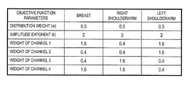
- FIG. 8 shows an example of objective function parameter values for each of the imaging sites.
- a database in which the combinations of the imaging sites and the objective function parameter values are set for each of the imaging sites is prepared in advance to be stored in the condition storage part 304 .
- a weight (w amp ) of the right channels 3 and 4 is set greater than a weight (w amp ) of the left channels 1 and 2 .
- the objective function parameter values can be set as follows:
- objective function parameter values can be set in combination with the above first embodiment.
- weights are varied between the upper and lower channels so that a weight (w amp ) of the lower channels is greater than a weight (w amp ) of the upper channels.
- the objective function parameter values can be set as follows:
- a weight (w amp ) of the left channels 1 and 2 is set greater than a weight (w amp ) of the right channels 3 and 4 . Furthermore, in a case where the object is disposed with the position shifted in the vertical direction, those weights may be changed even between the upper and lower channels.
- the second embodiment previously stores objective function parameter values for each of the imaging sites (and/or imaging purposes), selects an objective function parameter value corresponding to the imaging site (and/or the imaging purpose) set by the operator from among the previously stored objective function parameter values for each of the imaging sites (and/or imaging purposes) according to the settings for the imaging site (and/or the imaging purpose) from an operator, and uses the selected value for setting an objective function. That is, different objective function parameter values are used according to the imaging site of the object (and/or the imaging purpose). Hence, SAR reduction as well as maintenance and improvement of B 1 distribution homogeneity can be achieved more accurately and easily according to an imaging site (and/or an imaging purpose) without detecting a position in which an object is disposed.
- the third embodiment is characterized by that an operator sets objective function parameter values.
- a GUI Graphic User Interface
- objective function parameters w, k, w amp
- a plurality of combinations of parameter values prepared in advance, and it may be configured so that the operator selects a desired combination from among the combinations.
- an objective function is set based on the input objective function parameter values in order to evaluate a high-frequency magnetic field condition for optimizing the objective function set under a restriction condition.
- FIG. 9 shows an example of a GUI for setting and inputting objective function parameter values.
- the example shown in FIG. 9 illustrates a GUI that displays a plurality of combinations of parameter values prepared in advance so that an operator selects a desired combination from among the combinations.
- “RF Shim Mode” is the setting item for the objective function parameter values, the following options are displayed by clicking this, and then an objective function parameter value is set by selecting an arbitrary one therefrom.
- the options mean respectively as follows:
- the optimization condition setting part 302 displays a GUI for setting and inputting objective function parameter values on the display device 110 and receives input of objective function parameter values by an operator in order to set an objective function based on the input objective function parameter values.
- Step S 1001 the imaging condition setting unit 310 displays a GUI for setting and inputting objective function parameter values on the display device 110 and receives input of objective function parameter values by an operator in order to set the input value as an objective function parameter value.
- Step S 1004 the optimization condition setting part 302 sets an objective function based on the objective function parameter value set in Step S 1001 .
- setting objective function parameter values by an operator is received in order to set an objective function based on the input objective function parameter values.
- an operator can freely select a channel that reduces a SAR.
- the fourth embodiment is characterized by that distances between an object and each channel are determined based on a positioning image in order to set objective function parameter values based on the determined distances.
- a positioning image of three orthogonal cross sections or the like is acquired before main imaging in order to determine an imaging position or an imaging region of an object. Then, a position in which the object is disposed in a magnetic field space can be determined using the positioning image.
- positions in which the respective channels of the transmission coil are arranged in the magnetic field space are previously known from data provided when the MRI apparatus was designed, and the values can be stored. Therefore, distances between the object and each of the channels can be evaluated based on the object disposition position determined using the positioning image and the design data for the disposition positions of each of the channels. Based on the evaluated distances, to which channel the object is relatively closer or from which channel the object is relatively farther can be determined.
- a weight (w amp ) of a channel in a position relatively closer to the object is set greater than a weight (w amp ) of a channel in a position relatively farther from the object.
- the weight (w amp ) of the channel may be determined based on a distance (d) between the object and each of the channels as shown in the following formula (4).
- w amp w max ⁇ exp( ⁇ d ) (4)
- w max is a maximum weight value
- ⁇ is a predetermined distance attenuation coefficient
- Disposition positions of the respective channels of the transmission coil in a magnetic field space are acquired from the design data of an MRI apparatus.
- the condition storage part 304 stores the disposition positions.
- the imaging position setting section 311 acquires a positioning image by performing a scout scan or the like in order to determine a disposition position of an object in a magnetic field space based on the acquired positioning image.
- the optimization condition setting part 302 evaluates distances between an object and each channel based on the disposition position of the object in the magnetic field space evaluated by the imaging position setting section 311 and the disposition position of each channel in the magnetic field space read from the condition storage part 304 . Based on the distances, a weight (w amp ) of a channel in a position relatively closer to the object is set greater than a weight (w amp ) of a channel in a position relatively farther from the object. Alternatively, weights (w amp ) of the respective channels are determined using the above formula (4).
- Step S 1002 the imaging position setting section 311 acquires a positioning image by performing a scout scan or the like. Then, as described above, distances between an object and each channel are evaluated based on the acquired positioning image.
- Step S 1004 the optimization condition setting part 302 sets a weight (w amp ) of a channel 1 in a position relatively closer to an object greater than a weight (w amp ) of a channel in a position relatively farther from the object based on the distances between the object and each channel that were evaluated in Step S 1002 .
- a weight (w amp ) of the channel as shown in the above formula (4) is determined.
- an objective function is set based on the determined weight (w amp ) of each channel.
- FIG. 10 shows an example of an orthogonal three-cross-section image that is a positioning image of an object imaged with the arms placed on the abdomen using the transmission coil with a plurality of channels that is illustrated in FIG. 2 .
- 1001 is an axial image
- 1002 is a sagittal image
- 1003 is a coronal image. From these cross-sectional images, it can be understood that the object is disposed with the position relatively shifted to the upper side in the vertical direction and to the left side in the horizontal direction.
- weights are set as follows. Since the distance between Channel 1 in the upper left and the object is the shortest, the weight (w amp ) is made to be relatively large.
- the weight (w amp ) Since the distance between Channel 3 in the lower right and the object is the longest, the weight (w amp ) is made to be relatively small. Furthermore, since the distances between Channel 4 in the upper right, Channel 2 in the lower left, and the object are halfway between both the distances, the weights (w amp ) are set to values halfway between both the distances.
- distances between an object and each channel are determined based on a positioning image in order to set an objective function by determining weights (w amp ) of each channel based on the determined distances.
- the weights (w amp ) of each channel can be set accurately, which can improve an accuracy of an objective function. Consequently, SAR reduction as well as maintenance and improvement of B 1 distribution homogeneity can be achieved.
- the fifth embodiment is characterized by determining a weight (w amp ) of each channel using a SAR of each channel of the transmission coil.
- a weight (w amp ) of each channel can be determined as the following formula (5) for example.
- q is a proportional coefficient. That is, a weight (w amp ) of a channel whose SAR is relatively large is set greater than a weight (w amp ) of a channel whose SAR is relatively small.
- a SAR of each channel varies depending on imaging conditions such as an imaging parameter value, an object attribute, and a disposition position of the object in a magnetic field space, it is basically desirable to measure each time these conditions vary.
- a SAR value of each channel according to the imaging conditions may be previously measured and stored in order to omit SAR measurement by selecting and using the stored value.
- the measured SAR of each channel varies according to a distance to an object. Specifically, a SAR of a channel disposed in a position close to the object tends to be greater than a SAR of a channel disposed in a position farther from the object. Therefore, by determining a weight (w amp ) of each channel as shown in FIG. 5 , the weight (w amp ) of each channel tends to be different according to a distance to the object. That is, a weight (w amp ) of a channel disposed in a position relatively closer to the object is to be set greater than a weight (w amp ) of a channel disposed in a position relatively farther from the object.
- the condition storage part 304 previously stores a SAR value of each channel according to imaging conditions. Additionally, in a case of measuring a SAR of each channel of the transmission coil each time, it is unnecessary to store SAR values of the respective channels according to the imaging conditions.
- the optimization condition setting part 302 measures a SAR of each channel of the transmission coil.
- a SAR value of each channel associated with imaging conditions substantially corresponding to imaging to be performed later is extracted from among SAR values of the respective channels according to the imaging conditions stored in the condition storage part 304 .
- a weight (w amp ) of each channel is determined, for example, as shown in the above formula (5) in order to set an objective function.
- Step S 1004 the optimization condition setting part 302 measures a SAR of each channel of the transmission coil or, alternatively, extracts a SAR value of each channel associated with imaging conditions substantially corresponding to imaging conditions for imaging to be performed later from the condition storage part 304 . Then, based on a SAR value of each channel, a weight (w amp ) of each channel is determined in order to set an objective function.
- a SAR for each of the channels is acquired in order to determine a weight (w amp ) of each channel using these values in the fifth embodiment.
- ROI 1 first region
- ROI 2 second region
Landscapes
- Physics & Mathematics (AREA)
- Health & Medical Sciences (AREA)
- Life Sciences & Earth Sciences (AREA)
- Condensed Matter Physics & Semiconductors (AREA)
- General Physics & Mathematics (AREA)
- Nuclear Medicine, Radiotherapy & Molecular Imaging (AREA)
- Engineering & Computer Science (AREA)
- High Energy & Nuclear Physics (AREA)
- General Health & Medical Sciences (AREA)
- Radiology & Medical Imaging (AREA)
- Surgery (AREA)
- Biomedical Technology (AREA)
- Heart & Thoracic Surgery (AREA)
- Medical Informatics (AREA)
- Molecular Biology (AREA)
- Pathology (AREA)
- Animal Behavior & Ethology (AREA)
- Biophysics (AREA)
- Public Health (AREA)
- Veterinary Medicine (AREA)
- Signal Processing (AREA)
- Magnetic Resonance Imaging Apparatus (AREA)
- Mobile Radio Communication Systems (AREA)
Applications Claiming Priority (3)
| Application Number | Priority Date | Filing Date | Title |
|---|---|---|---|
| JP2014084603 | 2014-04-16 | ||
| PCT/JP2015/059032 WO2015159664A1 (ja) | 2014-04-16 | 2015-03-25 | 核磁気共鳴撮像装置およびrfシミング方法 |
| JP2014-084603 | 2015-04-17 |
Publications (2)
| Publication Number | Publication Date |
|---|---|
| US20170108564A1 US20170108564A1 (en) | 2017-04-20 |
| US10156616B2 true US10156616B2 (en) | 2018-12-18 |
Family
ID=54323876
Family Applications (1)
| Application Number | Title | Priority Date | Filing Date |
|---|---|---|---|
| US15/127,866 Active 2035-06-17 US10156616B2 (en) | 2014-04-16 | 2015-03-25 | Nuclear magnetic resonance imaging apparatus and RF shimming method |
Country Status (4)
| Country | Link |
|---|---|
| US (1) | US10156616B2 (zh) |
| JP (1) | JP6527138B2 (zh) |
| CN (2) | CN106028928B (zh) |
| WO (1) | WO2015159664A1 (zh) |
Families Citing this family (1)
| Publication number | Priority date | Publication date | Assignee | Title |
|---|---|---|---|---|
| CN108020797B (zh) * | 2016-11-03 | 2020-11-10 | 上海东软医疗科技有限公司 | 磁共振发射线圈及核磁共振成像设备 |
Citations (11)
| Publication number | Priority date | Publication date | Assignee | Title |
|---|---|---|---|---|
| US20050231203A1 (en) | 2004-03-18 | 2005-10-20 | Thorsten Feiweier | Method and magnetic resonance system for homogenizing the B1 field |
| US20080100292A1 (en) | 2006-10-30 | 2008-05-01 | Ileana Hancu | System and method for fast mr coil sensitivity mapping |
| US20080129298A1 (en) * | 2006-02-17 | 2008-06-05 | Vaughan J T | High field magnetic resonance |
| US20080238425A1 (en) | 2007-03-30 | 2008-10-02 | Dan Xu | System and method for designing improved rf pulse profiles |
| US20100253344A1 (en) | 2009-04-06 | 2010-10-07 | Hans-Peter Fautz | Magnetic resonance method and apparatus to determine k-space positions for modeling radio-frequency pulses |
| US20100301859A1 (en) | 2007-10-26 | 2010-12-02 | Nicolas Boulant | Method and Apparatus for Correcting B1-Inhomogeneities in Nuclear Magnetic Resonance Imaging |
| US20110156704A1 (en) * | 2008-09-17 | 2011-06-30 | Koninklijke Philips Electronics N.V. | B1-mapping and b1l-shimming for mri |
| CN102159966A (zh) | 2008-09-17 | 2011-08-17 | 皇家飞利浦电子股份有限公司 | 利用用于mri的多信道rf发射系统的具有rf功率正则化的rf匀场 |
| JP2013505046A (ja) | 2009-09-17 | 2013-02-14 | コーニンクレッカ フィリップス エレクトロニクス エヌ ヴィ | Mriにおけるrfパワー及びrfフィールド均一性の同時最適化 |
| US20130251227A1 (en) | 2012-02-27 | 2013-09-26 | Jinghua Wang | Methods and apparatus for accurate characterization of signal coil receiver sensitivity in magnetic resonance imaging (mri) |
| WO2014021172A1 (ja) | 2012-08-03 | 2014-02-06 | 株式会社日立メディコ | 磁気共鳴撮像装置および高周波磁場条件決定方法 |
Family Cites Families (11)
| Publication number | Priority date | Publication date | Assignee | Title |
|---|---|---|---|---|
| US6306348B1 (en) * | 1993-11-01 | 2001-10-23 | Nanogen, Inc. | Inorganic permeation layer for micro-electric device |
| CN1249942C (zh) * | 2003-05-13 | 2006-04-05 | 武汉汉网高技术有限公司 | 正交频分复用系统中的随机接入方法 |
| CN101282567B (zh) * | 2007-04-03 | 2011-09-21 | 中兴通讯股份有限公司 | 一种支持多种多址接入的系统 |
| DE112010004554T5 (de) * | 2009-11-24 | 2012-09-06 | Electronics And Telecommunications Research Institute | Verfahren zum Wiederherstellen eines Rahmens, dessen Übertragung in einem MU-MIMO-gestützten drahtlosen Kommunikationssystem fehlgeschlagen ist |
| CA2787774C (en) * | 2010-01-22 | 2019-02-12 | Sharp Kabushiki Kaisha | Transmission device, reception device, communication system, and communication method |
| US9668283B2 (en) * | 2010-05-05 | 2017-05-30 | Qualcomm Incorporated | Collision detection and backoff window adaptation for multiuser MIMO transmission |
| US8653818B2 (en) * | 2011-04-08 | 2014-02-18 | Siemens Aktiengesellschaft | Parallel transmission RF pulse design with local SAR constraints |
| EP2762070B1 (en) * | 2011-09-29 | 2021-06-09 | Hitachi, Ltd. | Magnetic resonance imaging equipment, high frequency magnetic field irradiation method and program |
| US20130195027A1 (en) * | 2012-01-30 | 2013-08-01 | Qualcomm Incorporated | Method and Apparatus for Channel Fallback in Enhanced Cell Forward Access Channel Dedicated Channel |
| WO2013141672A1 (ko) * | 2012-03-23 | 2013-09-26 | 엘지전자 주식회사 | 상향링크 신호 전송 방법 및 스테이션 장치와, 상향링크 신호 수신 방법 및 액세스 포인트 장치 |
| US9301150B2 (en) * | 2013-06-03 | 2016-03-29 | Qualcomm Incorporated | Methods and apparatus for clear channel assessment |
-
2015
- 2015-03-25 WO PCT/JP2015/059032 patent/WO2015159664A1/ja active Application Filing
- 2015-03-25 JP JP2016513693A patent/JP6527138B2/ja active Active
- 2015-03-25 US US15/127,866 patent/US10156616B2/en active Active
- 2015-03-25 CN CN201580010607.0A patent/CN106028928B/zh active Active
-
2016
- 2016-04-14 CN CN201680022342.0A patent/CN107960154B/zh active Active
Patent Citations (12)
| Publication number | Priority date | Publication date | Assignee | Title |
|---|---|---|---|---|
| US20050231203A1 (en) | 2004-03-18 | 2005-10-20 | Thorsten Feiweier | Method and magnetic resonance system for homogenizing the B1 field |
| US20080129298A1 (en) * | 2006-02-17 | 2008-06-05 | Vaughan J T | High field magnetic resonance |
| US20080100292A1 (en) | 2006-10-30 | 2008-05-01 | Ileana Hancu | System and method for fast mr coil sensitivity mapping |
| US20080238425A1 (en) | 2007-03-30 | 2008-10-02 | Dan Xu | System and method for designing improved rf pulse profiles |
| US20100301859A1 (en) | 2007-10-26 | 2010-12-02 | Nicolas Boulant | Method and Apparatus for Correcting B1-Inhomogeneities in Nuclear Magnetic Resonance Imaging |
| US20110156704A1 (en) * | 2008-09-17 | 2011-06-30 | Koninklijke Philips Electronics N.V. | B1-mapping and b1l-shimming for mri |
| CN102159966A (zh) | 2008-09-17 | 2011-08-17 | 皇家飞利浦电子股份有限公司 | 利用用于mri的多信道rf发射系统的具有rf功率正则化的rf匀场 |
| JP2012502683A (ja) | 2008-09-17 | 2012-02-02 | コーニンクレッカ フィリップス エレクトロニクス エヌ ヴィ | Mriのb1マッピング及びb1シミング |
| US20100253344A1 (en) | 2009-04-06 | 2010-10-07 | Hans-Peter Fautz | Magnetic resonance method and apparatus to determine k-space positions for modeling radio-frequency pulses |
| JP2013505046A (ja) | 2009-09-17 | 2013-02-14 | コーニンクレッカ フィリップス エレクトロニクス エヌ ヴィ | Mriにおけるrfパワー及びrfフィールド均一性の同時最適化 |
| US20130251227A1 (en) | 2012-02-27 | 2013-09-26 | Jinghua Wang | Methods and apparatus for accurate characterization of signal coil receiver sensitivity in magnetic resonance imaging (mri) |
| WO2014021172A1 (ja) | 2012-08-03 | 2014-02-06 | 株式会社日立メディコ | 磁気共鳴撮像装置および高周波磁場条件決定方法 |
Non-Patent Citations (7)
| Title |
|---|
| B. Van Den Bergen, "7 T Body MRI: B1 Shimming with Simultaneous SAR Reduction," Physics in Medicine and Biology, V.52 N. 17, pp. 5429-5441 (Sep. 7, 2007). |
| Chinese official action dated Aug. 29, 2018 in corresponding Chinese Patent Application No. 201580010607.0. |
| E.A.Attardo et al. "Field Synthesis in Inhomogeneous Media: Joint Control of Polarization, Uniformity and SAR in MRI B1-Field", Progress In Electromagnetics Research, vol. 118, pp. 355-377, 2011. |
| International Search Report in connection with PCT/JP2015/059032. |
| Lin Tang et al. "Studies of RF Shimming Techniques with Minimization of RF Power Deposition and Their Associated Temperature Changes", Concepts Magn Reson Part B Magn Reson Eng. pp. 1-25, 2011. |
| P. Balchandani et al. "Adiabatic B1 Shimming Algorithm for Multiple Channel Transmit at 7T" Proc. Intl. Soc. Mag: Reson. Med. 19. p. 2907, 2011. |
| R. Lattanzi et al. "Electrodynamic analysis of SAR and transmit homogeneity for RF shimming on a dielectric cylinder" Proc. Intl. Soc. Mag. Reson. Med. 17. p. 4510, 2009. |
Also Published As
| Publication number | Publication date |
|---|---|
| US20170108564A1 (en) | 2017-04-20 |
| CN106028928B (zh) | 2019-06-07 |
| JP6527138B2 (ja) | 2019-06-05 |
| JPWO2015159664A1 (ja) | 2017-04-13 |
| WO2015159664A1 (ja) | 2015-10-22 |
| CN107960154B (zh) | 2022-05-10 |
| CN106028928A (zh) | 2016-10-12 |
| CN107960154A (zh) | 2018-04-24 |
Similar Documents
| Publication | Publication Date | Title |
|---|---|---|
| JP6071905B2 (ja) | 磁気共鳴イメージング装置及び領域撮像方法 | |
| US7944209B2 (en) | Magnetic resonance imaging apparatus and method | |
| US9606205B1 (en) | Magnetic resonance imaging apparatus, RF shimming method, and magnetic resonance imaging method | |
| US10175324B2 (en) | Magnetic resonance imaging apparatus and method for control thereof | |
| US20150241539A1 (en) | Magnetic resonance imaging device, and determination method for high-frequency magnetic field conditions | |
| US20160231396A1 (en) | Magnetic resonance imaging apparatus and imaging parameter setting assisting method | |
| JP6162142B2 (ja) | 磁気共鳴イメージング装置、及び、sarの予測方法 | |
| Brink et al. | The effect of high-permittivity pads on specific absorption rate in radiofrequency-shimmed dual-transmit cardiovascular magnetic resonance at 3T | |
| US20130285660A1 (en) | Controlling a Magnetic Resonance System | |
| US10527696B2 (en) | Magnetic resonance imaging apparatus and SAR computing method | |
| US20090206835A1 (en) | Magnetic Resonance Imaging Apparatus and Method | |
| US9726744B2 (en) | Magnetic resonance imaging equipment, high frequency magnetic field irradiation method and program | |
| US10156616B2 (en) | Nuclear magnetic resonance imaging apparatus and RF shimming method | |
| JP6017443B2 (ja) | 磁気共鳴イメージング装置および照射磁場分布計測方法 | |
| KR101671267B1 (ko) | 고주파 펄스 조정 방법 및 고주파 펄스 조정 장치 | |
| WO2016143460A1 (ja) | 磁気共鳴イメージング装置およびrfシミングパラメータの設定方法 | |
| US10139462B2 (en) | Magnetic resonance imaging apparatus and magnetic resonance spectroscopic method using the same | |
| US20120262170A1 (en) | Method and device for determining a magnetic resonance system control sequence | |
| US9594137B2 (en) | Controlling magnetic resonance systems | |
| JP6513493B2 (ja) | 磁気共鳴撮像装置 | |
| JP2015019813A (ja) | 磁気共鳴イメージング装置及び補正用b1マップを計算する方法 | |
| JP6103965B2 (ja) | 磁気共鳴イメージング装置及びrfシミング方法 | |
| WO2016181868A1 (ja) | 磁気共鳴撮像装置、情報処理装置および高周波磁場シミング方法 |
Legal Events
| Date | Code | Title | Description |
|---|---|---|---|
| AS | Assignment |
Owner name: HITACHI, LTD., JAPAN Free format text: ASSIGNMENT OF ASSIGNORS INTEREST;ASSIGNOR:ITO, KOSUKE;REEL/FRAME:039818/0894 Effective date: 20160725 |
|
| STCF | Information on status: patent grant |
Free format text: PATENTED CASE |
|
| AS | Assignment |
Owner name: FUJIFILM HEALTHCARE CORPORATION, JAPAN Free format text: ASSIGNMENT OF ASSIGNORS INTEREST;ASSIGNOR:HITACHI, LTD.;REEL/FRAME:058026/0559 Effective date: 20211013 |
|
| AS | Assignment |
Owner name: FUJIFILM HEALTHCARE CORPORATION, JAPAN Free format text: CORRECTIVE ASSIGNMENT TO CORRECT THE THE PROPERTY AND APPLICATION NUMBERS PREVIOUSLY RECORDED AT REEL: 058026 FRAME: 0559. ASSIGNOR(S) HEREBY CONFIRMS THE ASSIGNMENT;ASSIGNOR:HITACHI LTD.;REEL/FRAME:058917/0853 Effective date: 20211013 |
|
| MAFP | Maintenance fee payment |
Free format text: PAYMENT OF MAINTENANCE FEE, 4TH YEAR, LARGE ENTITY (ORIGINAL EVENT CODE: M1551); ENTITY STATUS OF PATENT OWNER: LARGE ENTITY Year of fee payment: 4 |