US10142992B2 - Method, base station, and user terminal for using location information of user terminal - Google Patents
Method, base station, and user terminal for using location information of user terminal Download PDFInfo
- Publication number
- US10142992B2 US10142992B2 US14/903,794 US201414903794A US10142992B2 US 10142992 B2 US10142992 B2 US 10142992B2 US 201414903794 A US201414903794 A US 201414903794A US 10142992 B2 US10142992 B2 US 10142992B2
- Authority
- US
- United States
- Prior art keywords
- communication
- discovery
- signal
- enb
- user terminals
- Prior art date
- Legal status (The legal status is an assumption and is not a legal conclusion. Google has not performed a legal analysis and makes no representation as to the accuracy of the status listed.)
- Active, expires
Links
Images


Classifications
-
- H04W72/048—
-
- H—ELECTRICITY
- H04—ELECTRIC COMMUNICATION TECHNIQUE
- H04W—WIRELESS COMMUNICATION NETWORKS
- H04W72/00—Local resource management
- H04W72/50—Allocation or scheduling criteria for wireless resources
- H04W72/51—Allocation or scheduling criteria for wireless resources based on terminal or device properties
-
- H—ELECTRICITY
- H04—ELECTRIC COMMUNICATION TECHNIQUE
- H04W—WIRELESS COMMUNICATION NETWORKS
- H04W48/00—Access restriction; Network selection; Access point selection
- H04W48/08—Access restriction or access information delivery, e.g. discovery data delivery
- H04W48/14—Access restriction or access information delivery, e.g. discovery data delivery using user query or user detection
-
- H—ELECTRICITY
- H04—ELECTRIC COMMUNICATION TECHNIQUE
- H04W—WIRELESS COMMUNICATION NETWORKS
- H04W8/00—Network data management
- H04W8/005—Discovery of network devices, e.g. terminals
-
- H—ELECTRICITY
- H04—ELECTRIC COMMUNICATION TECHNIQUE
- H04W—WIRELESS COMMUNICATION NETWORKS
- H04W48/00—Access restriction; Network selection; Access point selection
- H04W48/16—Discovering, processing access restriction or access information
-
- H—ELECTRICITY
- H04—ELECTRIC COMMUNICATION TECHNIQUE
- H04W—WIRELESS COMMUNICATION NETWORKS
- H04W92/00—Interfaces specially adapted for wireless communication networks
- H04W92/16—Interfaces between hierarchically similar devices
- H04W92/18—Interfaces between hierarchically similar devices between terminal devices
Definitions
- the present invention relates to a network apparatus and a communication control method which are used in a mobile communication system that supports device-to-device (D2D) communication.
- D2D device-to-device
- Non Patent Literature 1 In the 3rd Generation Partnership Project (3GPP) that is a mobile communication system standardization project, introduction of device-to-device (D2D) communication into Release 12 as a new function is under consideration (see Non Patent Literature 1).
- 3GPP 3rd Generation Partnership Project
- D2D device-to-device
- a plurality of nearby user terminals perform direct inter-terminal communication without passing through a network.
- user terminals perform communication via a network.
- the user terminal transmits and receives a discovery signal used for discovering a nearby user terminal in order to perform the D2D communication. After the discovery process, the user terminal performs the D2D communication with the nearby user terminal.
- Non Patent Literature 1 3GPP Technical Report “TR 22.803 V12.1.0,” March, 2013
- D2D communication resources used for transmission and reception of the discovery signal
- D2D communication resources used for transmission and reception of user data in the D2D communication
- a network apparatus is included in a network of a mobile communication system that supports device-to-device (D2D) communication that is direct inter-terminal communication.
- the network apparatus includes a controller configured to set discovery resources that are radio resources used for transmission or reception of a discovery signal for performing the D2D communication.
- the controller controls a quantity of the discovery resources based on information on a user terminal existing in a target area that is a setting target area of the discovery resources.
- a communication control method is used in a mobile communication system that supports device-to-device (D2D) communication that is direct inter-terminal communication.
- the communication control method includes a step of setting, by a network apparatus included in a network of the mobile communication system, discovery resources that are radio resources used for transmission or reception of a discovery signal for performing the D2D communication.
- the network apparatus controls a quantity of the discovery resources based on information on a user terminal existing in a target area that is a setting target area of the discovery resources.
- FIG. 1 is a configuration diagram illustrating an LTE system according to an embodiment.
- FIG. 2 is a block diagram illustrating a UE according to an embodiment.
- FIG. 3 is a block diagram illustrating an eNB according to an embodiment.
- FIG. 4 is a protocol stack diagram illustrating a radio interface according to an embodiment.
- FIG. 5 is a configuration diagram illustrating a radio frame according to an embodiment.
- FIG. 6 is a diagram illustrating D2D communication according to an embodiment.
- FIG. 7 is a diagram illustrating a format of discovery resources according to an embodiment.
- FIGS. 8( a ) and 8( b ) are diagrams illustrating a first operation pattern according to an embodiment.
- FIG. 9 is a sequence diagram of the first operation pattern according to an embodiment.
- FIG. 10 is a flowchart illustrating a flow of calculating a discovery time in the first operation pattern according to an embodiment.
- FIGS. 11( a ) and 11( b ) are diagrams illustrating a second operation pattern according to an embodiment.
- FIG. 12 is a sequence diagram illustrating a third operation pattern according to an embodiment.
- FIG. 13 is a flowchart illustrating a flow of calculating a discovery time in the third operation pattern according to an embodiment.
- FIGS. 14( a ) and 14( b ) are diagrams illustrating a fourth operation pattern according to an embodiment.
- FIG. 15 is a diagram illustrating an interference between UEs that differ in a setting of a discovery time.
- FIG. 16 is a diagram illustrating another format of discovery resources.
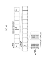
- FIG. 17 is another flowchart illustrating a flow of calculating a discovery time in the third operation pattern according to an embodiment.
- a network apparatus is included in a network of a mobile communication system that supports device-to-device (D2D) communication that is direct inter-terminal communication.
- the network apparatus includes a controller configured to set discovery resources that are radio resources used for transmission or reception of a discovery signal for performing the D2D communication.
- the controller controls a quantity of the discovery resources based on information on a user terminal existing in a target area that is a setting target area of the discovery resources.
- the target area is a cell of the mobile communication system.
- the controller controls the quantity of the discovery resources set to the cell based on information on the user terminal existing in the cell.
- the information on the user terminal is information indicating number of user terminals existing in the target area.
- the information on the user terminal is information indicating a density of user terminals existing in the target area.
- the information on the user terminal is information indicating an attribute of the user terminal existing in the target area.
- the information on the user terminal is information indicating transmission power of the discovery signal in the user terminal existing in the target area.
- the information on the user terminal is information on a result of a discovery process using the discovery signal in the user terminal existing in the target area.
- the information on the user terminal is information indicating a size of the cell in which the user terminal exists.
- a communication control method is used in a mobile communication system that supports device-to-device (D2D) communication that is direct inter-terminal communication.
- the communication control method includes a step of setting, by a network apparatus included in a network of the mobile communication system, discovery resources that are radio resources used for transmission or reception of a discovery signal for performing the D2D communication.
- the network apparatus controls a quantity of the discovery resources based on information on a user terminal existing in a target area that is a setting target area of the discovery resources.
- FIG. 1 is a configuration diagram of an LTE system according to a first embodiment.
- the LTE system includes a plurality of UEs (User Equipments) 100 , E-UTRAN (Evolved-UMTS Terrestrial Radio Access Network) 10 , and EPC (Evolved Packet Core) 20 .
- UEs User Equipments
- E-UTRAN Evolved-UMTS Terrestrial Radio Access Network
- EPC Evolved Packet Core
- the UE 100 corresponds to a user terminal.
- the UE 100 is a mobile communication device and performs radio communication with a cell (a serving cell) with which a connection is established. Configuration of the UE 100 will be described later.
- the E-UTRAN 10 corresponds to a radio access network.
- the E-UTRAN 10 includes a plurality of eNBs (evolved Node-Bs) 200 .
- the eNB 200 corresponds to a base station.
- the eNBs 200 are connected mutually via an X2 interface. Configuration of the eNB 200 will be described later.
- the eNB 200 manages one or a plurality of cells and performs radio communication with the UE 100 which establishes a connection with the cell of the eNB 200 .
- the eNB 200 has a radio resource management (RRM) function, a routing function for user data, and a measurement control function for mobility control and scheduling, and the like.
- RRM radio resource management
- the “cell” is used as a term indicating a minimum unit of a radio communication area, and is also used as a term indicating a function of performing radio communication with the UE 100 .
- the EPC 20 corresponds to a core network.
- the EPC 20 includes a plurality of MME (Mobility Management Entity)/S-GWs (Serving-Gateways) 300 .
- the MME performs various mobility controls and the like for the UE 100 .
- the S-GW performs control to transfer user.
- MME/S-GW 300 is connected to eNB 200 via an S1 interface.
- FIG. 2 is a block diagram of the UE 100 .
- the UE 100 includes plural antennas 101 , a radio transceiver 110 , a user interface 120 , a GNSS (Global Navigation Satellite System) receiver 130 , a battery 140 , a memory 150 , and a processor 160 .
- the memory 150 and the processor 160 constitute a controller.
- the UE 100 may not have the GNSS receiver 130 .
- the memory 150 may be integrally formed with the processor 160 , and this set (that is, a chip set) may be called a processor 160 ′.
- the plural antennas 101 and the radio transceiver 110 are used to transmit and receive a radio signal.
- the radio transceiver 110 converts a baseband signal (a transmission signal) output from the processor 160 into the radio signal and transmits the radio signal from the antenna 101 . Furthermore, the radio transceiver 110 converts a radio signal received by the antenna 101 into a baseband signal (a received signal), and outputs the baseband signal to the processor 160 .
- the user interface 120 is an interface with a user carrying the UE 100 , and includes, for example, a display, a microphone, a speaker, various buttons and the like.
- the user interface 120 accepts an operation from a user and outputs a signal indicating the content of the operation to the processor 160 .
- the GNSS receiver 130 receives a GNSS signal in order to obtain location information indicating a geographical location of the UE 100 , and outputs the received signal to the processor 160 .
- the battery 140 accumulates power to be supplied to each block of the UE 100 .
- the memory 150 stores a program to be executed by the processor 160 and information to be used for a process by the processor 160 .
- the processor 160 includes a baseband processor that performs modulation and demodulation, encoding and decoding and the like on the baseband signal, and CPU (Central Processing Unit) that performs various processes by executing the program stored in the memory 150 .
- the processor 160 may further include a codec that performs encoding and decoding on sound and video signals.
- the processor 160 executes various processes and various communication protocols described later.
- FIG. 3 is a block diagram of the eNB 200 .
- the eNB 200 includes plural antennas 201 , a radio transceiver 210 , a network interface 220 , a memory 230 , and a processor 240 .
- the memory 230 and the processor 240 constitute a controller.
- the plural antennas 201 and the radio transceiver 210 are used to transmit and receive a radio signal.
- the radio transceiver 210 converts a baseband signal (a transmission signal) output from the processor 240 into the radio signal and transmits the radio signal from the antenna 201 . Furthermore, the radio transceiver 210 converts a radio signal received by the antenna 201 into a baseband signal (a received signal), and outputs the baseband signal to the processor 240 .
- the network interface 220 is connected to the neighboring eNB 200 via the X2 interface and is connected to the MME/S-GW 300 via the S1 interface.
- the network interface 220 is used in communication over the X2 interface and communication over the S1 interface.
- the memory 230 stores a program to be executed by the processor 240 and information to be used for a process by the processor 240 .
- the processor 240 includes a baseband processor that performs modulation and demodulation, encoding and decoding and the like on the baseband signal and CPU that performs various processes by executing the program stored in the memory 230 .
- the processor 240 executes various processes and various communication protocols described later.
- FIG. 4 is a protocol stack diagram of a radio interface in the LTE system. As illustrated in FIG. 4 , the radio interface protocol is classified into a layer 1 to a layer 3 of an OSI reference model, wherein the layer 1 is a physical (PHY) layer.
- the layer 2 includes a MAC (Medium Access Control) layer, an RLC (Radio Link Control) layer, and a PDCP (Packet Data Convergence Protocol) layer.
- the layer 3 includes an RRC (Radio Resource Control) layer.
- the PHY layer performs encoding and decoding, modulation and demodulation, antenna mapping and demapping, and resource mapping and demapping. Between the PHY layer of the UE 100 and the PHY layer of the eNB 200 , use data and control signal are transmitted via the physical channel.
- the MAC layer performs priority control of data, a retransmission process by hybrid ARQ (HARQ), and the like.
- HARQ hybrid ARQ
- user data and control signal are transmitted via a transport channel.
- the MAC layer of the eNB 200 includes a scheduler that determines a transport format of an uplink and a downlink (a transport block size and a modulation and coding scheme) and a resource block to be assigned to the UE 100 .
- the RLC layer transmits data to an RLC layer of a reception side by using the functions of the MAC layer and the PHY layer. Between the RLC layer of the UE 100 and the RLC layer of the eNB 200 , user data and control signal are transmitted via a logical channel.
- the PDCP layer performs header compression and decompression, and encryption and decryption.
- the RRC layer is defined only in a control plane dealing with control signal. Between the RRC layer of the UE 100 and the RRC layer of the eNB 200 , control message (RRC messages) for various types of configuration are transmitted.
- the RRC layer controls the logical channel, the transport channel, and the physical channel in response to establishment, re-establishment, and release of a radio bearer.
- RRC connected state an RRC connected state
- RRC idle state an idle state
- a NAS (Non-Access Stratum) layer positioned above the RRC layer performs a session management, a mobility management and the like.
- FIG. 5 is a configuration diagram of a radio frame used in the LTE system.
- OFDMA Orthogonal Frequency Division Multiplexing Access
- SC-FDMA Single Carrier Frequency Division Multiple Access
- the radio frame is configured by 10 subframes arranged in a time direction, wherein each subframe is configured by two slots arranged in the time direction.
- Each subframe has a length of 1 ms and each slot has a length of 0.5 ms.
- Each subframe includes a plurality of resource blocks (RBs) in a frequency direction, and a plurality of symbols in the time direction.
- the resource block includes a plurality of subcarriers in the frequency direction. One subcarrier and one symbol constitute one resource element.
- a frequency resource can be specified by a resource block and a time resource can be specified by a subframe (or slot).
- an interval of several symbols at the head of each subframe is a control region used as a physical downlink control channel (PDCCH) for mainly transmitting a control signal. Furthermore, the other interval of each subframe is a region available as a physical downlink shared channel (PDSCH) for mainly transmitting user data.
- PDCH physical downlink control channel
- PDSCH physical downlink shared channel
- both ends in the frequency direction of each subframe are control regions used as a physical uplink control channel (PUCCH) for mainly transmitting a control signal. Furthermore, the other portion of each subframe is a region available as a physical uplink shared channel (PUSCH) for mainly transmitting user data.
- PUCCH physical uplink control channel
- PUSCH physical uplink shared channel
- the LTE system supports the D2D communication that is direct inter-terminal communication (inter-UE communication).
- inter-UE communication direct inter-terminal communication
- the cellular communication is a communication mode in which a data path passes through a network (the E-UTRAN 10 and the EPC 20 ).
- the data path refers to a communication path of user data.
- the D2D communication is a communication mode in which a data path set between the UEs does not pass through a network.
- FIG. 6 is a diagram illustrating the D2D communication.
- the data path does not pass through the eNB 200 as illustrated in FIG. 6 .
- the UE 100 - 1 and the UE 100 - 2 that are close to each other directly perform radio communication at low transmission power in the cell of the eNB 200 .
- the UE 100 transmits or receives the discovery signal used for discovering the nearby UE 100 in order to perform the D2D communication. After the discovery process, the UE 100 performs the D2D communication with the nearby UE 100 .
- radio resources used for transmission and reception of the discovery signal
- radio resources used for transmission and reception of at least user data in the D2D communication.
- the discovery resources are secured, it is possible to increase a probability that the nearby UE 100 will be discovered successfully, but since the D2D communication resources or the cellular communication resources are relatively reduced, the system throughput decreases.
- the eNB 200 sets the discovery resources serving as the radio resources used for transmission and reception of the discovery signal in order to perform the D2D communication. For example, the eNB 200 sets the D2D communication resources and the discovery resources in the radio resources secured for the D2D communication in a time division manner. Alternatively, the eNB 200 may set the D2D communication resources and the discovery resources in a frequency division manner. The following description will proceed with an example in which the D2D communication resources and the discovery resources are set in the time division manner.
- the eNB 200 controls a discovery resource quantity (duration) based on information on the UE 100 existing in a target area serving as a discovery resource setting target area.
- the target area is a cell.
- the target area may be a tracking area.
- the discovery resource quantity may be controlled for each UE 100 .
- “exist” does not depend on whether the UE 100 is in an idle state (an RRC idle state) or a connected state (an RRC connected state).
- the eNB 200 controls the discovery resource quantity based on the information on the UE 100 existing in the target area as described above, it is possible to adaptively set the discovery resource quantity according to a state of the UE 100 existing in the target area. Thus, the discovery resources can appropriately be set.
- An operation of controlling the discovery resource quantity includes first to seventh operation patterns described below.
- the first to seventh operation patterns will be described in detail later, but an overview of each operation pattern is described here.
- the first to seventh operation patterns need not be necessarily independently performed and two or more patterns are combined and performed.
- the eNB 200 controls the discovery resource quantity based on information indicating the number of UEs 100 existing in the target area.
- the eNB 200 controls the discovery resource quantity based on information indicating transmission power of the discovery signal in the UE 100 existing in the target area.
- the eNB 200 controls the discovery resource quantity based on information indicating the density of the UEs 100 existing in the target area.
- the eNB 200 controls the discovery resource quantity based on information on a result of the discovery process using the discovery signal in the UE 100 existing in the target area.
- the eNB 200 controls the discovery resource quantity based on information indicating the size of the cell in which the UE 100 exists.
- the eNB 200 controls the discovery resource quantity based on the information indicating the attribute of the UE 100 existing in the target area.
- the eNB 200 controls the discovery resource quantity based on the information indicating the frequency band used for transmission and reception of the discovery signal by the UE 100 existing in the target area.
- FIG. 7 is a diagram illustrating a format of the discovery resources according to an embodiment.
- the D2D communication resources and the discovery resources are set in the time division manner.
- the D2D communication resources are the radio resources used for transmission and reception of user data (and a control signal) in the D2D communication.
- the discovery resources are the radio resources used for transmission and reception of the discovery signal. For example, code division multiplexing using an orthogonal code is applied to the discovery resources.
- an interval of several symbols from the head corresponds to the discovery resources, and the remaining interval corresponds to the D2D communication resources.
- the interval corresponding to the discovery resources is referred to as a “discovery time,” and the interval corresponding to the D2D communication resources is referred to as a “D2D communication time (communication time).”
- a duration obtained by adding the discovery time and the D2D communication time is a predetermined duration (a subframe length in the example of FIG. 7 ).
- the discovery time is increased, the D2D communication time is relatively decreased, and the D2D communication capacity (the throughput of the D2D communication) decreases.
- the discovery time is decreased, the D2D communication time is relatively increased, the D2D communication capacity (the throughput of the D2D communication) is improved.
- the discovery resources and the D2D communication resources can be set in units of symbols within the subframe in the time division manner, but the present invention is not limited thereto, and the discovery resources and the D2D communication resources may be set in units of subframes within the radio frame in the time division manner.
- the UE 100 are allocated the discovery resources (time and frequency resources) and an orthogonal code from the eNB 200 .
- the UE 100 transmits and receives the discovery signal using the discovery resources and the orthogonal code allocated from the eNB 200 .
- the eNB 200 controls the discovery time based on the information indicating the number of UEs 100 existing in the target area.
- the information indicating the number of UEs 100 include the number of UEs 100 in the connected state in its own cell or the number of UEs 100 in the idle state in the tracking area including its own cell.
- the eNB 200 can acquire the number of UEs 100 in the idle state from the MME 300 .
- the number of UEs 100 may be limited to the number of UEs 100 that support the D2D communication. In this case, the eNB 200 acquires information indicating whether or not the D2D communication is supported from the UE 100 .
- FIGS. 8( a ) and 8( b ) are diagrams illustrating the first operation pattern. As illustrated in FIGS. 8( a ) and 8( b ) , when the number of UEs 100 is large, the eNB 200 increases the discovery time and decreases the discovery time when the number of UEs 100 is small. By controlling the discovery time according to the number of UEs 100 , it is possible to set the discovery resource quantity suitable for the number of UEs 100 .
- both the discovery time and the code length are increased.
- increasing the code length it is possible to increase the number of available orthogonal codes, and thus it is possible to allocate the orthogonal code for the discovery signal to the more UEs 100 .
- the code length of the orthogonal code applied in the discovery time is fixed, the number of available orthogonal codes is fixed, and thus the number of UEs accommodatable in the discovery time is increased by increasing the discovery time.
- the discovery time By increasing the discovery time to be n times a duration (a unit duration) corresponding to one orthogonal code, it is possible to increase the number of UEs accommodatable in the discovery time by n times.
- both the discovery time may be decreased (the D2D communication time may be increased), and the frequency resources in the discovery time may be decreased as well.
- the number of UEs 100 is small, some resource blocks rather than all resource blocks in the subframe secured for the D2D communication are used as the discovery resources and the D2D communication resources.
- FIG. 9 is a sequence diagram illustrating the first operation pattern.
- the eNB 200 calculates the discovery time based on the number of UEs 100 in its own cell. A discovery time calculation flow will be described later.
- the eNB 200 notifies the UE 100 in its own cell of the calculated discovery time in a unicast or broadcast manner. The UE 100 may transmit a response to the notified discovery time to the eNB 200 (step S 13 ).
- FIG. 10 is a flowchart illustrating the discovery time calculation flow in the first operation pattern.
- the eNB 200 determines whether or not the UE 100 exists in its own cell. When a determination result in step S 111 is “NO,” in step S 112 , the eNB 200 sets the discovery time to zero. When a determination result in step S 111 is “Yes,” in step S 113 , the eNB 200 determines whether or not the number of UEs 100 in its own cell is equal to or more than a maximum of the number of UEs accommodatable in the discovery time.
- step S 114 the eNB 200 sets the discovery time to a maximum value.
- step S 115 the eNB 200 determines whether or not the number of UEs 100 in its own cell exceeds a maximum of the number of UEs to which code division multiplexing can be applied.
- step S 117 the eNB 200 sets a value (a decimal is rounded up) obtained by dividing the number of UEs 100 in its own cell by a maximum of the number of UEs accommodatable in a minimum discovery time as the discovery time.
- step S 116 the eNB 200 sets a value that is twice the minimum discovery time as the discovery time.
- the eNB 200 controls the discovery resource quantity based on the information indicating the transmission power of the discovery signal in the UE 100 existing in the target area.
- the eNB 200 can use information of the managed transmission power of the discovery signal.
- the eNB 200 acquire the information indicating the transmission power of the discovery signal from the UE 100 and use the acquired information.
- the information indicating the transmission power of the discovery signal may be a statistic (an average value, a maximum value, a minimum value, a mode value, or the like) of the transmission power of the discovery signal in the UE 100 in its own cell.
- FIGS. 11( a ) and 11( b ) are diagrams illustrating the second operation pattern.
- the eNB 200 increases the discovery time when the transmission power of the discovery signal is low but decreases the discovery time when the transmission power of the discovery signal is high.
- the transmission power of the discovery signal decreases, an arrival range of the discovery signal decreases, and thus a probability that the discovery process will be performed successfully decreases.
- the discovery time increases, the probability that the discovery process will be performed successfully increases.
- the transmission power of the discovery signal is low, the probability that the discovery process will be performed successfully can be maintained at a certain level by increasing the discovery time.
- a sequence of notifying the UE 100 of the discovery time decided by the eNB 200 is similar to that in the first operation pattern.
- the eNB 200 controls the discovery resource quantity based on the information indicating the density of the UEs 100 existing in the target area.
- the information indicating the density of the UEs 100 is an inter-UE path loss or an inter-UE distance based on UE position information.
- each UE 100 transmits a reference signal of known transmission power, and thus a difference between reception power and transmission power when the reference signal is received in each UE 100 may be acquired from each UE 100 as the inter-UE path loss.
- the eNB 200 may use GNSS position information acquired from the UE 100 as the UE position information.
- the eNB 200 increases the discovery time when the density of the UEs 100 in its own cell is low and decreases the discovery time when the density of the UEs 100 in its own cell is high. As the density of the UEs 100 decreases, the probability that the discovery process will be performed successfully decreases. On the other hand, as the discovery time increases, the probability that the discovery process will be performed successfully increases. Thus, when the density of the UEs 100 is low, the probability that the discovery process will be performed successfully can be maintained at a certain level by increasing the discovery time. Alternatively, in order to discover all UEs within a certain range, the discovery time may be increased when the density of the UEs 100 in its own cell is high, and the discovery time may be decreased when the density of the UEs 100 in its own cell is low.
- FIG. 12 is a sequence diagram illustrating the third operation pattern.
- the eNB 200 requests the UE 100 in its own cell (the UEs 100 - 1 to 100 - 3 ) to transmit the inter-UE path loss.
- the UEs 100 - 1 to 100 - 3 transmits a list of inter-UE path losses to the eNB 200 .
- step S 23 also step S 302 in FIG.
- the eNB 200 decides the discovery time based on the list of the inter-UE path losses for each of the UEs 100 - 1 to 100 - 3 .
- a discovery time decision flow will be described later.
- the eNB 200 notifies the UEs 100 - 1 to 100 - 3 of the decided discovery time in the unicast manner, which is thus received by the UEs 100 - 1 to 100 - 3 (step S 304 in FIG. 17 ).
- the UEs 100 - 1 to 100 - 3 may transmit a response to the notified discovery time to the eNB 200 , and can thus use the discovery resource (step S 305 in FIG. 17 ).
- FIG. 13 is a flowchart illustrating the discovery time calculation flow in the third operation pattern. As illustrated in FIG. 13 , a process of steps S 231 to S 234 is performed by each of the UEs 100 . In step S 231 , the eNB 200 determines whether or not the number of UEs that can be discovered in the minimum discovery time is equal to or more than a minimum of the number of discoverable UEs based on the list of the inter-UE path losses acquired from the target UE 100 .
- a value that is, estimated reception power of the discovery signal
- a threshold value For example, when a value (that is, estimated reception power of the discovery signal) obtained by subtracting the inter-UE path loss from the transmission power of the discovery signal is equal to or more than a threshold value, it can be determined that it is possible to discover the neighboring UE 100 corresponding to the inter-UE path loss.
- a determination result in step S 231 is “NO,” a loop for deciding the discovery time starts, and when the discovery time is less than the maximum discovery time (NO in step S 232 ), the unit discovery time is added to the discovery time (step S 233 ).
- the process gets out of the loop, and the discovery time is stored (step S 234 ).
- the eNB 200 controls the discovery resource quantity based on the information on the result of the discovery process using the discovery signal in the UE 100 existing in the target area. For example, a result of the discovery process is reported from the UE 100 to the eNB 200 , and thus the eNB 200 can use information on the result of the discovery process.
- FIGS. 14( a ) and 14( b ) are diagrams illustrating the fourth operation pattern.
- the eNB 200 increases the current discovery time when the UE 100 has discovered no nearby UE in a previous discovery process, and decreases the current discovery time when the UE 100 has discovered a nearby UE in the previous discovery process.
- a target value of the number of nearby UEs discovered in the discovery process may be set, and the discovery time may be adjusted to become the target value. For example, a method of increasing the discovery time until it reaches a minimum of the number of discoverable UEs and decreasing the discovery time until it falls below a maximum of the number of discoverable UEs may be employed.
- the eNB 200 controls the discovery resource quantity based on the information indicating the size of the cell in which the UE 100 exists.
- the information indicating the size of the cell may be a cell type (a macro cell, a pico cell, a femto cell) or may be information indicating a radius, a diameter, or transmission power of the cell.
- the eNB 200 increases the discovery time so that the arrival range of the discovery time is increased. As the size of its own cell decreases, the eNB 200 decreases the discovery time so that the arrival range of the discovery time is decreased.
- the eNB 200 controls the discovery resource quantity based on the information indicating the attribute of the UE 100 existing in the target area.
- the attribute of the UE 100 refers to a contract condition (for example, a contract in which “the UE can be discovered at a distance of up to 10 m or 20 m” or “up to 10 UEs or 20 UEs can be discovered.”).
- the attribute of the UE 100 may be a type of the UE 100 (for example, a public safety UE or a common UE).
- the eNB 200 may acquire the information indicating the attribute of the UE 100 from the UE 100 and use the acquired information.
- the eNB 200 adjusts the discovery time so that the contract condition is satisfied. Further, for the public safety UE, the eNB 200 increases the discovery time to be higher in a success rate of the discovery process than for the common UE. Specifically, a required arrival range of the discovery signal differs according to a type of UE. Further, when the discovery signals to which the orthogonal codes of the different code lengths are applied are used together in the same cell without dividing resources, interference occurs. In order to avoid it, the code length of the orthogonal code applied to the discovery signal is set to the same length, the discovery time is increased, and the number of repetitions in repetitive transmission of the discovery signal is changed according to a type of UE. Further, a reception duration of the discovery time is decided according to a type of UE. Accordingly, the discovery range required for each UE can be implemented.
- the eNB 200 controls the discovery resource quantity based on the information indicating the frequency band used for transmission and reception of the discovery signal by the UE 100 existing in the target area.
- the eNB 200 can use information indicating the specified frequency bands.
- the UE 100 reports the frequency band used for transmission and reception of the discovery signal to the eNB 200 , and the eNB 200 can use the information indicating the frequency band used for transmission and reception of the discovery signal by the UE 100 .
- the eNB 200 decreases the discovery time when the frequency band used for transmission and reception of the discovery signal is low.
- the eNB 200 increases the discovery time when the frequency band used for transmission and reception of the discovery signal is high.
- the eNB 200 controls the discovery time based on the information on the UE 100 existing in the target area.
- the discovery time can adaptively be set according to the state of the UE 100 existing in the target area.
- the discovery time can appropriately be set.
- the eNB 200 has been described as an example of the network apparatus according to the present invention, but the network apparatus according to the present invention is not limited to the eNB 200 and may be a higher-level device (the MME 300 , the OAM, or the like) of the eNB 200 .
- the discovery time has been described as being set in units of tracking areas, units of cells, or units of UEs, but when a plurality of UEs 100 that differ in a setting of the discovery time get closer to each other, an interference problem is likely to occur.
- FIG. 15 is a diagram illustrating interference between UEs that differ in a setting of the discovery time.
- the discovery time for the UE to which the long discovery time is set overlaps (collides with) a portion of the D2D communication time in another UE to which the short discovery time is set. At a reception side, it is difficult to decode the overlapping portion.
- the eNB 200 (or the UE 100 ) that has detected interference caused by the overlapping may employ any one of the following interference avoidance methods.
- a first method is a method of changing transmission power of UEs that interfere with each other. In this case, a priority may be given to the discovery signal (the discovery time), or a priority may be given to the user data (the D2D communication time).
- a second method is a method of shifting transmission timings or use frequencies of UEs that interfere with each other.
- a third method is a method of increasing the number of repetitive transmissions of the discovery time in order to give interference resistance to the discovery signal (the discovery time).
- FIG. 16 is a diagram illustrating another format of the discovery resources. As illustrated in FIG. 16 , the discovery resources are set to a specific resource block in a specific communication frequency band in the frequency direction. Further, the discovery resources are set to a specific symbol in a specific subframe in the time direction.
- the LTE system has been described as an example of the cellular communication system, but the cellular communication system is not limited to the LTE system, and the present invention may be applied to a system other than the LTE system.
- the present invention is useful in mobile communication fields.
Landscapes
- Engineering & Computer Science (AREA)
- Computer Networks & Wireless Communication (AREA)
- Signal Processing (AREA)
- Databases & Information Systems (AREA)
- Computer Security & Cryptography (AREA)
- Mobile Radio Communication Systems (AREA)
Applications Claiming Priority (3)
| Application Number | Priority Date | Filing Date | Title |
|---|---|---|---|
| JP2013-144025 | 2013-07-09 | ||
| JP2013144025A JP2015019177A (ja) | 2013-07-09 | 2013-07-09 | ネットワーク装置及び通信制御方法 |
| PCT/JP2014/068136 WO2015005316A1 (fr) | 2013-07-09 | 2014-07-08 | Dispositif de réseau et procédé de commande de communication |
Related Parent Applications (1)
| Application Number | Title | Priority Date | Filing Date |
|---|---|---|---|
| PCT/JP2014/068136 A-371-Of-International WO2015005316A1 (fr) | 2013-07-09 | 2014-07-08 | Dispositif de réseau et procédé de commande de communication |
Related Child Applications (1)
| Application Number | Title | Priority Date | Filing Date |
|---|---|---|---|
| US16/165,793 Continuation US10624102B2 (en) | 2013-07-09 | 2018-10-19 | Method, base station, and user terminal for using location information of user terminal |
Publications (2)
| Publication Number | Publication Date |
|---|---|
| US20160165585A1 US20160165585A1 (en) | 2016-06-09 |
| US10142992B2 true US10142992B2 (en) | 2018-11-27 |
Family
ID=52279996
Family Applications (2)
| Application Number | Title | Priority Date | Filing Date |
|---|---|---|---|
| US14/903,794 Active 2034-11-15 US10142992B2 (en) | 2013-07-09 | 2014-07-08 | Method, base station, and user terminal for using location information of user terminal |
| US16/165,793 Active US10624102B2 (en) | 2013-07-09 | 2018-10-19 | Method, base station, and user terminal for using location information of user terminal |
Family Applications After (1)
| Application Number | Title | Priority Date | Filing Date |
|---|---|---|---|
| US16/165,793 Active US10624102B2 (en) | 2013-07-09 | 2018-10-19 | Method, base station, and user terminal for using location information of user terminal |
Country Status (3)
| Country | Link |
|---|---|
| US (2) | US10142992B2 (fr) |
| JP (1) | JP2015019177A (fr) |
| WO (1) | WO2015005316A1 (fr) |
Cited By (2)
| Publication number | Priority date | Publication date | Assignee | Title |
|---|---|---|---|---|
| US20170142647A1 (en) * | 2014-08-05 | 2017-05-18 | Huawei Technologies Co., Ltd. | D2D Station, System and D2D Discovery Method |
| US10601460B2 (en) * | 2014-09-26 | 2020-03-24 | Huawei Technologies Co., Ltd. | D2D signal frequency hopping method and base station |
Families Citing this family (9)
| Publication number | Priority date | Publication date | Assignee | Title |
|---|---|---|---|---|
| JP2015019177A (ja) | 2013-07-09 | 2015-01-29 | 京セラ株式会社 | ネットワーク装置及び通信制御方法 |
| CN105376869B (zh) * | 2014-08-22 | 2020-04-03 | 中兴通讯股份有限公司 | 一种在非授权载波上发送发现信号的方法、系统及接入点 |
| JPWO2016163501A1 (ja) * | 2015-04-09 | 2018-03-15 | 株式会社Nttドコモ | ユーザ端末、無線基地局及び無線通信方法 |
| JP6419017B2 (ja) * | 2015-04-23 | 2018-11-07 | 三菱電機株式会社 | 移動局、無線通信システム、およびリソース割当方法 |
| JP6696504B2 (ja) * | 2015-06-02 | 2020-05-20 | 日本電気株式会社 | 無線端末装置、ネットワークノード、及び方法 |
| WO2017051740A1 (fr) * | 2015-09-24 | 2017-03-30 | 株式会社Nttドコモ | Dispositif d'utilisateur, station de base, procédé de communication, et procédé de notification |
| US10904729B2 (en) * | 2016-12-20 | 2021-01-26 | Verizon Patent And Licensing Inc. | System and method for improved capacity using channel multiplexing |
| JP2018057032A (ja) * | 2017-12-04 | 2018-04-05 | 京セラ株式会社 | 基地局、通信制御方法、及びユーザ端末 |
| KR102000157B1 (ko) * | 2017-12-11 | 2019-07-15 | 서울대학교산학협력단 | 서비스 품질을 보장하는 무선 통신 방법 및 장치 |
Citations (9)
| Publication number | Priority date | Publication date | Assignee | Title |
|---|---|---|---|---|
| US20080069039A1 (en) | 2006-09-15 | 2008-03-20 | Qualcomm Incorporated | Methods and apparatus related to power control and/or interference management in a mixed wireless communications system supporting wan signaling and peer to peer signaling |
| WO2009154270A1 (fr) | 2008-06-20 | 2009-12-23 | 日本電気株式会社 | Procede d’attribution de ressources, procede d’identification, systeme de communication radio, station de base, station mobile et programme |
| US20100202400A1 (en) | 2009-02-12 | 2010-08-12 | Qualcomm Incorporated | Transmission with collision detection and mitigation for wireless communication |
| WO2011130630A1 (fr) | 2010-04-15 | 2011-10-20 | Qualcomm Incorporated | Émission et réception d'un signal de détection de proximité pour la découverte de pairs |
| US20120182890A1 (en) * | 2011-01-19 | 2012-07-19 | Qualcomm Incorporated | Adaptive peer discovery based on non peer discovery transmissions and device density for wi-fi |
| US20130195026A1 (en) * | 2012-01-27 | 2013-08-01 | Kerstin Johnsson | Centralized control of intra-cell device-to-device communication |
| US20140301326A1 (en) | 2011-09-09 | 2014-10-09 | Qualcomm Incorporated | Methods and apparatus for wan assisted contention detection & resolution in peer to peer networks |
| JP2015019177A (ja) | 2013-07-09 | 2015-01-29 | 京セラ株式会社 | ネットワーク装置及び通信制御方法 |
| US20160021676A1 (en) * | 2013-02-18 | 2016-01-21 | Kyocera Corporation | Base station and communication control method |
-
2013
- 2013-07-09 JP JP2013144025A patent/JP2015019177A/ja active Pending
-
2014
- 2014-07-08 US US14/903,794 patent/US10142992B2/en active Active
- 2014-07-08 WO PCT/JP2014/068136 patent/WO2015005316A1/fr active Application Filing
-
2018
- 2018-10-19 US US16/165,793 patent/US10624102B2/en active Active
Patent Citations (17)
| Publication number | Priority date | Publication date | Assignee | Title |
|---|---|---|---|---|
| US20080069039A1 (en) | 2006-09-15 | 2008-03-20 | Qualcomm Incorporated | Methods and apparatus related to power control and/or interference management in a mixed wireless communications system supporting wan signaling and peer to peer signaling |
| JP2012090283A (ja) | 2006-09-15 | 2012-05-10 | Qualcomm Inc | Wan信号伝送およびピアツーピア信号伝送をサポートする混在無線通信システムにおける電力制御および/または干渉処理に関する方法および装置 |
| WO2009154270A1 (fr) | 2008-06-20 | 2009-12-23 | 日本電気株式会社 | Procede d’attribution de ressources, procede d’identification, systeme de communication radio, station de base, station mobile et programme |
| US20110110322A1 (en) * | 2008-06-20 | 2011-05-12 | Nec Corporation | Resource allocation method, identification method, radio communication system, base station, mobile station, and program |
| JP2012517784A (ja) | 2009-02-12 | 2012-08-02 | クアルコム,インコーポレイテッド | ワイヤレス通信のための衝突検出および緩和を用いた送信 |
| US20100202400A1 (en) | 2009-02-12 | 2010-08-12 | Qualcomm Incorporated | Transmission with collision detection and mitigation for wireless communication |
| WO2011130630A1 (fr) | 2010-04-15 | 2011-10-20 | Qualcomm Incorporated | Émission et réception d'un signal de détection de proximité pour la découverte de pairs |
| JP2013529416A (ja) | 2010-04-15 | 2013-07-18 | クゥアルコム・インコーポレイテッド | ピア発見のための近接検知信号の送信及び受信 |
| US20170006458A1 (en) | 2010-04-15 | 2017-01-05 | Qualcomm Incorporated | Transmission and reception of proximity detection signal for peer discovery |
| WO2012099829A1 (fr) | 2011-01-19 | 2012-07-26 | Qualcomm Incorporated | Découverte de pairs adaptative sur la base de transmissions autre que de découverte de pairs et de densité de dispositifs pour wifi |
| US20120182890A1 (en) * | 2011-01-19 | 2012-07-19 | Qualcomm Incorporated | Adaptive peer discovery based on non peer discovery transmissions and device density for wi-fi |
| US20140301326A1 (en) | 2011-09-09 | 2014-10-09 | Qualcomm Incorporated | Methods and apparatus for wan assisted contention detection & resolution in peer to peer networks |
| JP2014530521A (ja) | 2011-09-09 | 2014-11-17 | クゥアルコム・インコーポレイテッドQualcomm Incorporated | ピアツーピアネットワークにおけるwan支援競合検出および解消のための方法および装置 |
| US20130195026A1 (en) * | 2012-01-27 | 2013-08-01 | Kerstin Johnsson | Centralized control of intra-cell device-to-device communication |
| US20160021676A1 (en) * | 2013-02-18 | 2016-01-21 | Kyocera Corporation | Base station and communication control method |
| JP2015019177A (ja) | 2013-07-09 | 2015-01-29 | 京セラ株式会社 | ネットワーク装置及び通信制御方法 |
| US20160165585A1 (en) | 2013-07-09 | 2016-06-09 | Kyocera Corporation | Network apparatus and communication control method |
Non-Patent Citations (4)
| Title |
|---|
| 3GPP TR 22.803, V12.1.0 (Mar. 2013), 3rd Generation Partnership Project; Technical Specification Group Services and System Aspects; Feasibility study for Proximity Services (ProSe), (Release 12), pp. 1-45. |
| An Office Action issued by the Japanese Patent Office dated Mar. 6, 2018, which corresponds to Japanese Patent Application No. 2017-232396 and is related to U.S. Appl. No. 14/903,794; with English language concise explanation. |
| Discussion about resource allocation schemes for D2D discovery, 3GPP TSG RAN WGI Meeting #73, R1-132211, Fukuoka, Japan, May 20-24, 2013, pp. 1-3. |
| International Search Report and Written Opinion of PCT/JP2014/068136 dated Oct. 14, 2014. |
Cited By (3)
| Publication number | Priority date | Publication date | Assignee | Title |
|---|---|---|---|---|
| US20170142647A1 (en) * | 2014-08-05 | 2017-05-18 | Huawei Technologies Co., Ltd. | D2D Station, System and D2D Discovery Method |
| US10425882B2 (en) * | 2014-08-05 | 2019-09-24 | Huawei Technologies Co., Ltd. | D2D station, system and D2D discovery method |
| US10601460B2 (en) * | 2014-09-26 | 2020-03-24 | Huawei Technologies Co., Ltd. | D2D signal frequency hopping method and base station |
Also Published As
| Publication number | Publication date |
|---|---|
| US20190059082A1 (en) | 2019-02-21 |
| US10624102B2 (en) | 2020-04-14 |
| WO2015005316A1 (fr) | 2015-01-15 |
| US20160165585A1 (en) | 2016-06-09 |
| JP2015019177A (ja) | 2015-01-29 |
Similar Documents
| Publication | Publication Date | Title |
|---|---|---|
| US10624102B2 (en) | Method, base station, and user terminal for using location information of user terminal | |
| US12004252B2 (en) | Mobile communication system, user terminal, and base station | |
| JP6328132B2 (ja) | 移動通信システム及びユーザ端末 | |
| US9642172B2 (en) | Mobile communication system, base station, user terminal, and processor | |
| US10021714B2 (en) | Mobile communication system and user terminal | |
| US11350460B2 (en) | Communication control method and radio terminal | |
| US9923689B2 (en) | Mobile communication system, user terminal, and processor for assigning radio resources for transmission of sounding reference signals and device to device communication resources | |
| US9719383B2 (en) | Network device and communication control method | |
| US10582525B2 (en) | Communication control method, base station, and user terminal, for performing D2D communication | |
| US9867223B2 (en) | Network apparatus and user terminal | |
| WO2018030228A1 (fr) | Procédé de communications mobiles, station de base, et équipement d'utilisateur | |
| US20150139176A1 (en) | Mobile communication system and user terminal | |
| US20160374055A1 (en) | Communication control method | |
| US10362524B2 (en) | Network apparatus and user terminal | |
| US10932300B2 (en) | Communication control method, radio terminal, and base station | |
| US9924496B2 (en) | Network apparatus and user terminal | |
| US9560688B2 (en) | Mobile communication system, user terminal, communication control apparatus, and communication control method | |
| US10015714B2 (en) | Network selection control method, base station, and user terminal | |
| JP2024514131A (ja) | 処理能力が制約されたシナリオにおいてマルチrtt測位を改善するためにprsとsrsとの関連付けを定義すること | |
| US20160021665A1 (en) | Mobile communication system, base station, and user terminal | |
| US20160157079A1 (en) | User terminal, network apparatus, and processor | |
| JP2018057032A (ja) | 基地局、通信制御方法、及びユーザ端末 | |
| US10348461B2 (en) | Communication apparatus and communication method |
Legal Events
| Date | Code | Title | Description |
|---|---|---|---|
| AS | Assignment |
Owner name: KYOCERA CORPORATION, JAPAN Free format text: ASSIGNMENT OF ASSIGNORS INTEREST;ASSIGNORS:SAIWAI, TAKAHIRO;MORITA, KUGO;FUJISHIRO, MASATO;REEL/FRAME:037440/0168 Effective date: 20151204 |
|
| STCF | Information on status: patent grant |
Free format text: PATENTED CASE |
|
| MAFP | Maintenance fee payment |
Free format text: PAYMENT OF MAINTENANCE FEE, 4TH YEAR, LARGE ENTITY (ORIGINAL EVENT CODE: M1551); ENTITY STATUS OF PATENT OWNER: LARGE ENTITY Year of fee payment: 4 |