US10136733B2 - Paper toweling or tissue dispensing apparatus including roll overspin control - Google Patents
Paper toweling or tissue dispensing apparatus including roll overspin control Download PDFInfo
- Publication number
- US10136733B2 US10136733B2 US15/894,492 US201815894492A US10136733B2 US 10136733 B2 US10136733 B2 US 10136733B2 US 201815894492 A US201815894492 A US 201815894492A US 10136733 B2 US10136733 B2 US 10136733B2
- Authority
- US
- United States
- Prior art keywords
- roll
- support
- hub projection
- core
- dispenser apparatus
- Prior art date
- Legal status (The legal status is an assumption and is not a legal conclusion. Google has not performed a legal analysis and makes no representation as to the accuracy of the status listed.)
- Active
Links
Images


Classifications
-
- A—HUMAN NECESSITIES
- A47—FURNITURE; DOMESTIC ARTICLES OR APPLIANCES; COFFEE MILLS; SPICE MILLS; SUCTION CLEANERS IN GENERAL
- A47C—CHAIRS; SOFAS; BEDS
- A47C21/00—Attachments for beds, e.g. sheet holders or bed-cover holders; Ventilating, cooling or heating means in connection with bedsteads or mattresses
- A47C21/02—Holders for loose bed elements, e.g. sheet holders; bed cover holders
- A47C21/028—Holders for facilitating making the bed
-
- A—HUMAN NECESSITIES
- A47—FURNITURE; DOMESTIC ARTICLES OR APPLIANCES; COFFEE MILLS; SPICE MILLS; SUCTION CLEANERS IN GENERAL
- A47K—SANITARY EQUIPMENT; ACCESSORIES THEREFOR, e.g. TOILET ACCESSORIES
- A47K10/00—Body-drying implements; Toilet paper; Holders therefor
- A47K10/24—Towel dispensers; Toilet paper dispensers
- A47K10/32—Dispensers for paper towels or toilet paper
- A47K10/34—Dispensers for paper towels or toilet paper dispensing from a web, e.g. with mechanical dispensing means
- A47K10/38—Dispensers for paper towels or toilet paper dispensing from a web, e.g. with mechanical dispensing means the web being rolled-up
-
- A—HUMAN NECESSITIES
- A47—FURNITURE; DOMESTIC ARTICLES OR APPLIANCES; COFFEE MILLS; SPICE MILLS; SUCTION CLEANERS IN GENERAL
- A47K—SANITARY EQUIPMENT; ACCESSORIES THEREFOR, e.g. TOILET ACCESSORIES
- A47K10/00—Body-drying implements; Toilet paper; Holders therefor
- A47K10/24—Towel dispensers; Toilet paper dispensers
- A47K10/32—Dispensers for paper towels or toilet paper
- A47K2010/3206—Coreless paper rolls
-
- A—HUMAN NECESSITIES
- A47—FURNITURE; DOMESTIC ARTICLES OR APPLIANCES; COFFEE MILLS; SPICE MILLS; SUCTION CLEANERS IN GENERAL
- A47K—SANITARY EQUIPMENT; ACCESSORIES THEREFOR, e.g. TOILET ACCESSORIES
- A47K10/00—Body-drying implements; Toilet paper; Holders therefor
- A47K10/24—Towel dispensers; Toilet paper dispensers
- A47K10/32—Dispensers for paper towels or toilet paper
- A47K10/34—Dispensers for paper towels or toilet paper dispensing from a web, e.g. with mechanical dispensing means
- A47K10/36—Dispensers for paper towels or toilet paper dispensing from a web, e.g. with mechanical dispensing means with mechanical dispensing, roll switching or cutting devices
- A47K2010/3675—Braking devices
-
- A—HUMAN NECESSITIES
- A47—FURNITURE; DOMESTIC ARTICLES OR APPLIANCES; COFFEE MILLS; SPICE MILLS; SUCTION CLEANERS IN GENERAL
- A47K—SANITARY EQUIPMENT; ACCESSORIES THEREFOR, e.g. TOILET ACCESSORIES
- A47K10/00—Body-drying implements; Toilet paper; Holders therefor
- A47K10/24—Towel dispensers; Toilet paper dispensers
- A47K10/32—Dispensers for paper towels or toilet paper
- A47K10/34—Dispensers for paper towels or toilet paper dispensing from a web, e.g. with mechanical dispensing means
- A47K10/38—Dispensers for paper towels or toilet paper dispensing from a web, e.g. with mechanical dispensing means the web being rolled-up
- A47K2010/3863—Dispensers for paper towels or toilet paper dispensing from a web, e.g. with mechanical dispensing means the web being rolled-up with roll rotation braking devices
Definitions
- This invention relates to dispenser apparatus for holding a roll of paper toweling or tissue sheet material and for dispensing the sheet material during rotation of the roll.
- Overspin of a roll paper product such as paper toweling pulled during dispensing can create slack in the dispensed toweling remaining in a dispenser after the desired length has been dispensed.
- the slack segment can interfere with subsequent proper operation of some dispensers.
- Dispenser arrangements which address the problem of overspin and slack creation. Such known devices are characterized by their relative complexity and high expense.
- the following patent documents are believed to be representative of the current state of the prior art in this field:
- the present invention relates to dispenser apparatus for holding a roll of paper toweling or tissue sheet material having centrally disposed first and second roll support openings at opposite ends thereof and for dispensing the sheet material during rotation of the roll.
- the dispenser apparatus includes a first roll support positioned in the first roll support opening, the first roll support operable to support the roll and allow rotation of the roll relative thereto to unwind the sheet material when a pulling force is applied to the sheet material.
- the first roll support is configured to exert frictional drag forces on the roll to reduce overspin of the roll when the pulling force is terminated.
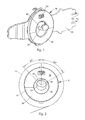
- FIG. 1 is a perspective view of a first embodiment of the invention attached to a dispenser apparatus roll support arm;
- FIG. 2 is an enlarged, elevational side view depicting in solid lines the inner side of the roll support of the first embodiment and depicting in dash lines the outline of a roll of paper toweling supported thereby, positions of spaced core structure contact points of the roll support at different angles relative to vertical being indicated;
- FIG. 3 is a front end view of the roll support of the first embodiment showing a hub projection thereof pivoted relative to a hub projection support and tilted downwardly from the position illustrated in FIG. 1 ;
- FIG. 4 is a front end view of a second embodiment illustrating the hub projection in a substantially horizontal, non-tilted position, the hub projection illustrated in FIG. 4 differing from the hub projection illustrated in FIGS. 1-3 in that the hub projection of FIG. 4 does not have a cut-away top portion as illustrated in FIGS. 1 and 3 ;
- FIG. 5 is a front view depicting a roll of paper toweling supported on one side by the roll support of FIGS. 1-3 and at the other side by a conventional roll support, each roll support attached to a dispenser apparatus roll support arm;
- FIG. 6 is an exploded, perspective view showing the first and second roll supports shown in FIG. 5 prior to assembly with the dispenser apparatus support arms and roll;
- FIG. 7 is an end view of a third embodiment of the invention wherein a hub projection of alternative construction is horizontally disposed and positioned in an end opening of a roll;
- FIG. 8 is an elevation, side view of the roll showing the hub projection embodiment of FIG. 7 positioned in the roll core, horizontally disposed, and supporting an end of the roll;
- FIG. 9 is a view similar to FIG. 7 wherein the hub projection has been pivoted and is inclined downwardly relative to horizontal;
- FIG. 10 is a view similar to FIG. 9 , but illustrating a fourth embodiment wherein a hub projection similar to that of the embodiment of FIG. 4 tilted downwardly relative to horizontal;
- FIG. 11 is an exploded, elevational front view illustrating a roll in dash lines with solid lines depicting two roll supports prior to insertion into the end openings of the roll, one of the roll supports being the roll support shown in FIG. 7 and the other roll support being of a conventional fixed projection type attached to the other roll support arm;
- FIG. 12 is a perspective view of the roll support embodiment of FIGS. 9 and 11 ;
- FIG. 13 discloses a fifth embodiment of the invention wherein the hub projection male portion is directly affixed to an inner surface of a dispenser apparatus roll support arm;
- FIG. 14 is an elevation side view depicting in solid lines a portion of the hub projection arm and the male portion of the hub projection of FIG. 13 positioned relative to a core of a roll illustrated in dash lines;
- FIG. 15 is a perspective view of a sixth embodiment of the invention holding a roll wherein the hub projection is an elongated fixed mandrel with an oval-shaped peripheral surface;
- FIG. 16 is an exploded view showing the roll separated from the hub projection of FIG. 15 ;
- FIG. 17 is a front elevation view of the FIG. 15 embodiment showing angular orientation of the hub projection relative to the roll;
- FIG. 18 is a perspective view illustrating an embodiment of the invention wherein a hub projection with generally rectangular outer peripheral surface having rounded corners projects from a roll support arm;
- FIG. 19 is a front elevational view of the embodiment of FIG. 18 .
- dispenser apparatus constructed in accordance with the teachings of the present invention is illustrated.
- the dispenser apparatus is for holding a roll 12 of paper toweling or tissue sheet material having roll support openings 14 , 16 at opposed ends thereof.
- the dispenser apparatus is for dispensing the sheet material during rotation of the roll caused by a pulling force applied to the sheet material.
- the approach for applying pulling force to the sheet material for accomplishing dispensing may be use of any known prior art mechanical mechanisms or simply applying such forces manually to the toweling or tissue directly.
- the dispenser apparatus incorporates a roll support 18 positioned in the roll support opening 14 and operable to support the roll and allow rotation of the roll relative thereto to unwind the sheet material when a pulling force is applied to the sheet material.
- the roll support 18 is configured to exert frictional drag forces on the roll 12 to reduce overspin of the roll when the pulling force is terminated.
- Roll support 18 is configured to hold the weight of the roll off center.
- the roll support 18 is connected to and projects inwardly from a roll support arm 20 which may be of any suitable type commonly used in toweling and tissue roll dispensers.
- a second roll support arm 24 is positioned at the other end of the roll and utilized to support the roll.
- Roll support arm 24 rotatably accommodates a plug 26 which is inserted into roll support opening 16 .
- This latter arrangement is commonly employed to support a roll end and is merely exemplary since any suitable known arrangement for supporting the end of the roll at roll support opening 16 and allowing rotation of the roll may be employed.
- Roll support 18 functions as an overspin control or reducer. This is accomplished by holding the weight of the roll off center.
- Roll support 18 includes a hub projection 28 and a hub projection support, the latter in this embodiment comprising a portion 30 of roll support arm 20 , the hub projection being pivotally mounted relative to the hub projection support.
- the hub projection includes a male portion 32 and a hub projection base 34 from which the male portion extends.
- the hub projection base 34 is connected by hinge 36 disposed at the bottom thereof with the hub projection support 30 of roll support arm 20 and is tiltable between the positions shown in FIGS. 1 and 3 .
- Retainer structure in the form of an elongated hook 38 on the hub projection base 34 extending through an aperture 40 of the hub projection support 30 limits pivotal movement between the hub projection and the hub projection support.
- the roll support 18 is configured to include spaced and distinct roll core contact points.
- the roll core contact points are disposed at different angles relative to vertical.
- Male portion 32 has an oval-shaped outer peripheral surface with two adjacent curved upper corners 42 , 44 forming the roll core contact points.
- the male portion has an oblong configuration and is canted, as may perhaps best be seen with respect to FIG. 2 , so that the roll core holds the weight of the roll off center, the core being shown in dash lines in FIG. 2 and designated by reference numeral 46 .
- the roll core contact points are disposed at different angles to the vertical. In FIG. 2 these angles are shown as 45 degrees and 60 degrees; however, the angles shown are relative to a specific core diameter and are tunable based on overspin reduction needed for a particular core diameter or other characteristic, such as if mated with a roll plug system and the frictional characteristics of the plug system.
- the hub projection male portion shape illustrated creates more frictional drag than a centered shape would, as can be depicted by a force diagram (not shown). If desired, a roll support similar to roll support 18 may also be employed at the other end of the roll as well.
- An upper segment of the male portion of the roll support 18 hub projection has been cut away to leave an opening 48 . This feature forces contact with the roll core away from the lateral face of the hub projection base 34 .
- FIG. 4 shows a second embodiment of the invention.
- components of the second embodiment are identical to the components of the first embodiment and share the same reference numbers.
- the male portion of this second embodiment identified by reference numeral 54 , has no cut-away upper portion and is slightly larger in size for accommodating a different sized roll core.
- FIGS. 7-9, 11 and 12 disclose another alternative embodiment of the invention.
- the roll support is identified by reference numeral 60 .
- the hub projection support is part of a roll support arm 20 and is of the same construction as the hub projection support previously described with other embodiments and bears the same reference number 30 .
- the hub projection 62 of this embodiment differs from that described above. More particularly, the male portion 64 and the shape of the hub projection base 66 differ.
- the hub projection male portion 64 is round rather than oblong in shape and has a single centered contact point 68 with the inside diameter of the roll core. This may best be seen with reference to FIG. 8 .
- the male portion 64 forms an upper space or void 70 between the distal end of the male portion and the outer surface of hub projection base 66 .
- FIG. 7 and FIG. 8 show the male portion 64 extending along a horizontal axis, that is, in untilted condition.
- the hub projection base of course is also untilted.
- hub projection base 66 has an upper slanted face portion 72 which extends downwardly somewhat beyond the center of the hub projection base.
- the upper slanted face portion may be cylindrical.
- face portion 74 tangentially disposed relative to the face portion 72 and located a slight distance below the center of the hub projection base.
- face portion 74 is shown engaging the end of the roll. The weight of the roll will move the hub projection 62 to a tilted orientation, as shown for example in FIG. 9 . The location where the roll end contacts the face varies with the amount of tilt or pivot.
- Overspin reduction or control is accomplished through bias with the end of the roll created by a moment arm of roll weight applied to the male portion of the hub projection which is offset from the pivot point located at the hinge 76 pivotally connecting the hub projection base to the hub projection support 30 of the roll support arm.
- the cut-away top portion of the male hub projection portion creates a larger moment arm than would be accomplished without an upper space or void 70 .
- the embodiment shown in FIG. 10 is identical to the embodiment of FIG. 9 except that the male portion 84 has no cut-away or void space. As indicated by the illustrated downwardly extending arrows in FIGS. 9 and 10 , the contact point of the male portion 84 with the roll core is substantially closer to the pivot point at hinge 76 , thus creating a considerably shorter moment arm.
- toweling rolls it is typical for toweling rolls to have a width tolerance of plus/minus 1 ⁇ 8 inch, or more.
- the pivoting hub projection arrangement allows the roll support system to absorb that tolerance without excessively squeezing the maximum width rolls.
- the bias with the end of the roll also keeps the roll positively engaged with both roll supports so that the narrow rolls will not fall off of the supports during dispensing.
- FIG. 11 shows a fixed roll holder projection 86 on the right roll support.
- FIGS. 13 and 14 show an embodiment of an invention wherein a hub projection male portion 90 is affixed to the inner surface of a roll support arm 20 , for example by being integrally molded therewith.
- the male portion has an oval configuration and is canted to provide two roll core contact points as described above with respect to the first embodiment of the invention.
- the male portion could have a generally oval configuration with flat surfaces disposed between curved corners, for example the generally rectangular male portion shape shown in FIGS. 18 and 19 .
- FIGS. 15-17 show a single fixed mandrel tissue dispenser 94 utilizing the overspin reducing concept disclosed herein.
- the dispenser cover is not shown.
- the hub projection male portion or mandrel 96 is elongated so that it contacts all or at least a significant portion of the length of the roll tissue core.
- the hub projection male portion or mandrel 96 is oval shaped, having two upper curved contact corners due to canting of the mandrel.
- FIGS. 18 and 19 show another embodiment of the invention wherein a hub projection male portion 98 having an outer surface of generally rectangular configuration is affixed to the inner surface of a roll support arm 20 , for example being integrally molded therewith.
- the roll contact points are at upper adjacent curved corners 100 of the hub projection male portion. These contact points are disposed on opposite sides of a vertical axis extending through the top-most, upper inner surface of said roll core and at the same angle (in this instance 40 degrees) relative to the vertical axis.
- overspin control features of this invention can be employed at left, right or both sides of a dual support system.
- the principles of the present invention can be applied to rolls wherein the core is a traditional separate core about which paper sheet material is wound thereabout or wherein the core is formed from the same toweling as the rest of the rolls, i.e. so-called careless-cored rolls.
Landscapes
- Health & Medical Sciences (AREA)
- Public Health (AREA)
- Unwinding Webs (AREA)
- Replacement Of Web Rolls (AREA)
Abstract
Description
Claims (10)
Priority Applications (1)
| Application Number | Priority Date | Filing Date | Title |
|---|---|---|---|
| US15/894,492 US10136733B2 (en) | 2015-02-24 | 2018-02-12 | Paper toweling or tissue dispensing apparatus including roll overspin control |
Applications Claiming Priority (2)
| Application Number | Priority Date | Filing Date | Title |
|---|---|---|---|
| US14/629,599 US9907442B2 (en) | 2015-02-24 | 2015-02-24 | Paper toweling or tissue dispensing apparatus including roll overspin control |
| US15/894,492 US10136733B2 (en) | 2015-02-24 | 2018-02-12 | Paper toweling or tissue dispensing apparatus including roll overspin control |
Related Parent Applications (2)
| Application Number | Title | Priority Date | Filing Date |
|---|---|---|---|
| US14/629,599 Continuation US9907442B2 (en) | 2015-02-24 | 2015-02-24 | Paper toweling or tissue dispensing apparatus including roll overspin control |
| US14629559 Continuation | 2015-02-24 |
Publications (2)
| Publication Number | Publication Date |
|---|---|
| US20180160818A1 US20180160818A1 (en) | 2018-06-14 |
| US10136733B2 true US10136733B2 (en) | 2018-11-27 |
Family
ID=56689642
Family Applications (2)
| Application Number | Title | Priority Date | Filing Date |
|---|---|---|---|
| US14/629,599 Active 2035-11-12 US9907442B2 (en) | 2015-02-24 | 2015-02-24 | Paper toweling or tissue dispensing apparatus including roll overspin control |
| US15/894,492 Active US10136733B2 (en) | 2015-02-24 | 2018-02-12 | Paper toweling or tissue dispensing apparatus including roll overspin control |
Family Applications Before (1)
| Application Number | Title | Priority Date | Filing Date |
|---|---|---|---|
| US14/629,599 Active 2035-11-12 US9907442B2 (en) | 2015-02-24 | 2015-02-24 | Paper toweling or tissue dispensing apparatus including roll overspin control |
Country Status (4)
| Country | Link |
|---|---|
| US (2) | US9907442B2 (en) |
| EP (2) | EP4026465A1 (en) |
| BR (1) | BR112017018143B1 (en) |
| WO (1) | WO2016137676A1 (en) |
Cited By (1)
| Publication number | Priority date | Publication date | Assignee | Title |
|---|---|---|---|---|
| US12507839B2 (en) | 2019-11-22 | 2025-12-30 | Gpcp Ip Holdings Llc | Frictional features for rolled sheet product dispensers |
Families Citing this family (12)
| Publication number | Priority date | Publication date | Assignee | Title |
|---|---|---|---|---|
| US9795258B2 (en) * | 2013-09-05 | 2017-10-24 | Dispensing Dynamics International, Llc | Dispenser apparatus with damper for dispensing paper toweling |
| US10045669B2 (en) * | 2014-06-27 | 2018-08-14 | Cascades Canaga Ulc | Rolled product dispenser |
| WO2016022949A1 (en) | 2014-08-08 | 2016-02-11 | Georgia-Pacific Consumer Products Lp | Sheet product dispensers and related methods for reducing sheet product usage |
| US9907442B2 (en) * | 2015-02-24 | 2018-03-06 | Dispensing Dynamics International, Llc | Paper toweling or tissue dispensing apparatus including roll overspin control |
| CA3009987A1 (en) | 2016-01-06 | 2017-07-13 | Essity Operations Wausau LLC | A rolled media dispenser |
| US10850938B2 (en) | 2017-10-09 | 2020-12-01 | Gpcp Ip Holdings Llc | Mechanical sheet product dispenser |
| US11089920B2 (en) | 2018-03-08 | 2021-08-17 | Dispensing Dynamics International, Inc. | Stub roll dispenser system |
| US11134811B2 (en) | 2018-03-09 | 2021-10-05 | Cascades Canada Ulc | Web material roll dispenser and roll support assembly for a web material roll dispenser |
| EP3952709B1 (en) | 2019-04-12 | 2025-12-03 | Dispensing Dynamics International, Inc. | Dispenser with automatic stub roll drop down |
| US11479431B2 (en) | 2019-07-19 | 2022-10-25 | Dispensing Dynamics International, Inc. | Dispensing systems with floating support rollers |
| GB202017786D0 (en) * | 2020-08-10 | 2020-12-23 | Kimberly Clark Co | Dispenser systems |
| AT524405B1 (en) * | 2020-10-16 | 2022-07-15 | Fitzthum Michael | Holder for reel |
Citations (31)
| Publication number | Priority date | Publication date | Assignee | Title |
|---|---|---|---|---|
| US1651867A (en) | 1926-08-16 | 1927-12-06 | Oliver R Boynton | Toilet-paper holder |
| US1802251A (en) * | 1928-06-15 | 1931-04-21 | Max Breth | Unwinding device for bolts of cloth |
| US1913363A (en) | 1931-07-06 | 1933-06-13 | Joseph H Allen | Toilet paper holder |
| US2164817A (en) | 1937-10-21 | 1939-07-04 | Leo M Harvey | Paper holder |
| US2370821A (en) | 1943-10-15 | 1945-03-06 | Harold R Stott | Paper roll holder |
| US2410328A (en) * | 1945-04-09 | 1946-10-29 | Fort Howard Paper Co | Toilet roll dispenser |
| US2514778A (en) * | 1944-08-19 | 1950-07-11 | Margo Murray | Holder |
| US2896871A (en) * | 1954-05-11 | 1959-07-28 | James E Woodruff | Roll paper storage receptacle and dispensing holder |
| US4222532A (en) * | 1979-04-10 | 1980-09-16 | Georgia-Pacific Corporation | Roll holder |
| US4234136A (en) * | 1978-04-26 | 1980-11-18 | Continental Gummi-Werke Aktiengesellschaft | Apparatus for the replaceable mounting of a winding drum for web-like material |
| US4610407A (en) | 1985-05-17 | 1986-09-09 | Clik-Cut, Inc. | Frictional drag arrangement for sheet material dispenser |
| US4858840A (en) * | 1988-04-08 | 1989-08-22 | Kidman L La Vere | Dispensing hanger for rolls of serially connected sheets |
| US5048386A (en) | 1989-10-27 | 1991-09-17 | Georgia-Pacific Corporation | Feed mechanism for flexible sheet material dispensers |
| US5215274A (en) | 1991-09-27 | 1993-06-01 | Lin Wen Yi | Supporting device for toilet tissue |
| US5249755A (en) | 1992-02-27 | 1993-10-05 | Georgia-Pacific Corporation | Brake-type sheet material-dispensing roll support |
| US5782428A (en) | 1996-09-27 | 1998-07-21 | Chabot; Claude | Roll holder having pivoting support arms |
| CA2256105A1 (en) | 1998-12-15 | 2000-06-15 | Wes Andrei | Dispenser for rolled sheet media |
| US6189828B1 (en) | 1999-11-08 | 2001-02-20 | Robert Reilly | Sanitary paper roll dispenser |
| US6286781B1 (en) | 2000-09-08 | 2001-09-11 | Yuan-Tse Lai | Holder for a roll of paper |
| US6415948B1 (en) | 1998-06-19 | 2002-07-09 | Maurice Granger | Device for controlling and limiting the drum rotation in a wiping material dispenser |
| US6666364B2 (en) * | 2001-12-07 | 2003-12-23 | Kimberly-Clark Worldwide, Inc. | Easy loading dispenser |
| US20040104300A1 (en) * | 2002-12-03 | 2004-06-03 | Friesen Jed C. | Paper towel holder |
| US20060236832A1 (en) | 2005-04-25 | 2006-10-26 | Perrin Manufacturing Company | Paper towel dispenser apparatus |
| US20060266873A1 (en) | 2005-03-31 | 2006-11-30 | Global Plastics, A British Columbia General Partnership | Core Replacement System |
| US7513453B2 (en) * | 2005-11-04 | 2009-04-07 | Georgia-Pacific France | System for dispensing paper in a coreless roll, method of manufacturing a roll of this type, and roll of paper |
| JP4478997B2 (en) | 2000-05-25 | 2010-06-09 | Toto株式会社 | Roll paper holder |
| US20130320128A1 (en) | 2012-05-29 | 2013-12-05 | Georgia-Pacific Consumer Products Lp | Sheet product dispenser with load inducement portion |
| US20140339281A1 (en) | 2013-05-17 | 2014-11-20 | Andrew Flocchini | Perforated paper towel dispenser for one-handed operation |
| US20150150422A1 (en) * | 2013-12-02 | 2015-06-04 | Dispensing Dynamics International | Multi-piece support for paper roll product |
| US20160242603A1 (en) * | 2015-02-24 | 2016-08-25 | Dispensing Dynamics International | Paper toweling or tissue dispensing apparatus including roll overspin control |
| US9895033B2 (en) * | 2014-12-05 | 2018-02-20 | Dispensing Dynamics International, Llc | Dispenser apparatus with damper for dispensing paper toweling |
Family Cites Families (5)
| Publication number | Priority date | Publication date | Assignee | Title |
|---|---|---|---|---|
| US2643069A (en) * | 1950-03-07 | 1953-06-23 | Arvid F Carlin | Holder for toilet paper and paper towels |
| US3318543A (en) * | 1965-10-22 | 1967-05-09 | Francis J Moore | Friction roll holder |
| US4974783A (en) * | 1989-10-30 | 1990-12-04 | James River Corporation | Dispenser cabinet for dispensing sheet material |
| DE102009031526A1 (en) * | 2009-07-02 | 2011-01-05 | Metallwarenfabrik Marktoberdorf Gmbh & Co. Kg | Papierrollenhalter |
| US20120138723A1 (en) * | 2010-12-02 | 2012-06-07 | Richard Paul Lewis | Dispenser Supply Roll Engagement System |
-
2015
- 2015-02-24 US US14/629,599 patent/US9907442B2/en active Active
-
2016
- 2016-02-02 EP EP22159297.5A patent/EP4026465A1/en not_active Withdrawn
- 2016-02-02 BR BR112017018143-6A patent/BR112017018143B1/en active IP Right Grant
- 2016-02-02 WO PCT/US2016/016051 patent/WO2016137676A1/en not_active Ceased
- 2016-02-02 EP EP16756041.6A patent/EP3261502A4/en not_active Withdrawn
-
2018
- 2018-02-12 US US15/894,492 patent/US10136733B2/en active Active
Patent Citations (32)
| Publication number | Priority date | Publication date | Assignee | Title |
|---|---|---|---|---|
| US1651867A (en) | 1926-08-16 | 1927-12-06 | Oliver R Boynton | Toilet-paper holder |
| US1802251A (en) * | 1928-06-15 | 1931-04-21 | Max Breth | Unwinding device for bolts of cloth |
| US1913363A (en) | 1931-07-06 | 1933-06-13 | Joseph H Allen | Toilet paper holder |
| US2164817A (en) | 1937-10-21 | 1939-07-04 | Leo M Harvey | Paper holder |
| US2370821A (en) | 1943-10-15 | 1945-03-06 | Harold R Stott | Paper roll holder |
| US2514778A (en) * | 1944-08-19 | 1950-07-11 | Margo Murray | Holder |
| US2410328A (en) * | 1945-04-09 | 1946-10-29 | Fort Howard Paper Co | Toilet roll dispenser |
| US2896871A (en) * | 1954-05-11 | 1959-07-28 | James E Woodruff | Roll paper storage receptacle and dispensing holder |
| US4234136A (en) * | 1978-04-26 | 1980-11-18 | Continental Gummi-Werke Aktiengesellschaft | Apparatus for the replaceable mounting of a winding drum for web-like material |
| US4222532A (en) * | 1979-04-10 | 1980-09-16 | Georgia-Pacific Corporation | Roll holder |
| US4610407A (en) | 1985-05-17 | 1986-09-09 | Clik-Cut, Inc. | Frictional drag arrangement for sheet material dispenser |
| US4858840A (en) * | 1988-04-08 | 1989-08-22 | Kidman L La Vere | Dispensing hanger for rolls of serially connected sheets |
| US5048386A (en) | 1989-10-27 | 1991-09-17 | Georgia-Pacific Corporation | Feed mechanism for flexible sheet material dispensers |
| US5215274A (en) | 1991-09-27 | 1993-06-01 | Lin Wen Yi | Supporting device for toilet tissue |
| US5249755A (en) | 1992-02-27 | 1993-10-05 | Georgia-Pacific Corporation | Brake-type sheet material-dispensing roll support |
| US5782428A (en) | 1996-09-27 | 1998-07-21 | Chabot; Claude | Roll holder having pivoting support arms |
| US6415948B1 (en) | 1998-06-19 | 2002-07-09 | Maurice Granger | Device for controlling and limiting the drum rotation in a wiping material dispenser |
| CA2256105A1 (en) | 1998-12-15 | 2000-06-15 | Wes Andrei | Dispenser for rolled sheet media |
| US6189828B1 (en) | 1999-11-08 | 2001-02-20 | Robert Reilly | Sanitary paper roll dispenser |
| JP4478997B2 (en) | 2000-05-25 | 2010-06-09 | Toto株式会社 | Roll paper holder |
| US6286781B1 (en) | 2000-09-08 | 2001-09-11 | Yuan-Tse Lai | Holder for a roll of paper |
| US6666364B2 (en) * | 2001-12-07 | 2003-12-23 | Kimberly-Clark Worldwide, Inc. | Easy loading dispenser |
| US20040104300A1 (en) * | 2002-12-03 | 2004-06-03 | Friesen Jed C. | Paper towel holder |
| US20060266873A1 (en) | 2005-03-31 | 2006-11-30 | Global Plastics, A British Columbia General Partnership | Core Replacement System |
| US20060236832A1 (en) | 2005-04-25 | 2006-10-26 | Perrin Manufacturing Company | Paper towel dispenser apparatus |
| US7513453B2 (en) * | 2005-11-04 | 2009-04-07 | Georgia-Pacific France | System for dispensing paper in a coreless roll, method of manufacturing a roll of this type, and roll of paper |
| US20130320128A1 (en) | 2012-05-29 | 2013-12-05 | Georgia-Pacific Consumer Products Lp | Sheet product dispenser with load inducement portion |
| US20140339281A1 (en) | 2013-05-17 | 2014-11-20 | Andrew Flocchini | Perforated paper towel dispenser for one-handed operation |
| US20150150422A1 (en) * | 2013-12-02 | 2015-06-04 | Dispensing Dynamics International | Multi-piece support for paper roll product |
| US9895033B2 (en) * | 2014-12-05 | 2018-02-20 | Dispensing Dynamics International, Llc | Dispenser apparatus with damper for dispensing paper toweling |
| US20160242603A1 (en) * | 2015-02-24 | 2016-08-25 | Dispensing Dynamics International | Paper toweling or tissue dispensing apparatus including roll overspin control |
| US9907442B2 (en) * | 2015-02-24 | 2018-03-06 | Dispensing Dynamics International, Llc | Paper toweling or tissue dispensing apparatus including roll overspin control |
Cited By (1)
| Publication number | Priority date | Publication date | Assignee | Title |
|---|---|---|---|---|
| US12507839B2 (en) | 2019-11-22 | 2025-12-30 | Gpcp Ip Holdings Llc | Frictional features for rolled sheet product dispensers |
Also Published As
| Publication number | Publication date |
|---|---|
| BR112017018143B1 (en) | 2022-10-04 |
| BR112017018143A2 (en) | 2018-04-10 |
| US20160242603A1 (en) | 2016-08-25 |
| US9907442B2 (en) | 2018-03-06 |
| WO2016137676A1 (en) | 2016-09-01 |
| US20180160818A1 (en) | 2018-06-14 |
| EP3261502A4 (en) | 2018-11-07 |
| EP3261502A1 (en) | 2018-01-03 |
| EP4026465A1 (en) | 2022-07-13 |
Similar Documents
| Publication | Publication Date | Title |
|---|---|---|
| US10136733B2 (en) | Paper toweling or tissue dispensing apparatus including roll overspin control | |
| US5868347A (en) | Rolled material holder and dispenser | |
| US5277375A (en) | Spindle for use with compressed core wound paper products | |
| US4012007A (en) | Paper towel holder | |
| EP2233420B1 (en) | Dispenser for elongate material | |
| US4452403A (en) | Dispenser for material arranged in a roll | |
| US8096495B2 (en) | Spindle for a roll of web material | |
| CA2225409A1 (en) | Container-dispenser of paper upon manual tearing from a roll, provided with another roll in reserve | |
| AU2020223745A1 (en) | Adhesive tape dispenser and an adhesive tape roll | |
| US4974783A (en) | Dispenser cabinet for dispensing sheet material | |
| US3950881A (en) | Fish line spool holder for transferring fishing line to reel | |
| US5782428A (en) | Roll holder having pivoting support arms | |
| WO2011013014A3 (en) | Hanging dispensing system | |
| US6390410B1 (en) | Versatile paper roll holder and dispenser | |
| US6619582B1 (en) | Paper roll holder | |
| JPH0318552A (en) | Tape dispenser | |
| US2994488A (en) | Roll material dispenser | |
| EP2070856A1 (en) | A hand-held device for applying a deposit of for example adhesive, covering or coloured material onto a correction surface | |
| EP2070857A1 (en) | A hand-held device for applying a deposit of for example adhesive, covering or coloured material onto a correction surface | |
| GB2287452A (en) | Roll material dispenser | |
| US20180249869A1 (en) | Toilet Tissue Holder and Dispenser | |
| JPS6128571B2 (en) | ||
| US1098864A (en) | Paper-holder. | |
| CN103889870A (en) | Tape dispenser | |
| US1272598A (en) | Paper-holder. |
Legal Events
| Date | Code | Title | Description |
|---|---|---|---|
| AS | Assignment |
Owner name: DISPENSING DYNAMICS INTERNATIONAL, LLC, CALIFORNIA Free format text: ASSIGNMENT OF ASSIGNORS INTEREST;ASSIGNOR:CVJETKOVIC, NIKO ANTHONY;REEL/FRAME:044902/0356 Effective date: 20180206 |
|
| FEPP | Fee payment procedure |
Free format text: ENTITY STATUS SET TO UNDISCOUNTED (ORIGINAL EVENT CODE: BIG.); ENTITY STATUS OF PATENT OWNER: LARGE ENTITY |
|
| STCF | Information on status: patent grant |
Free format text: PATENTED CASE |
|
| AS | Assignment |
Owner name: AWAY FROM HOME ACQUISITION COMPANY, CALIFORNIA Free format text: ASSIGNMENT OF ASSIGNORS INTEREST;ASSIGNOR:DISPENSING DYNAMICS INTERNATIONAL, LLC;REEL/FRAME:053207/0532 Effective date: 20170616 Owner name: DISPENSING DYNAMICS INTERNATIONAL, INC., CALIFORNIA Free format text: CHANGE OF NAME;ASSIGNOR:AWAY FROM HOME ACQUISITION COMPANY;REEL/FRAME:053210/0104 Effective date: 20170628 |
|
| MAFP | Maintenance fee payment |
Free format text: PAYMENT OF MAINTENANCE FEE, 4TH YEAR, LARGE ENTITY (ORIGINAL EVENT CODE: M1551); ENTITY STATUS OF PATENT OWNER: LARGE ENTITY Year of fee payment: 4 |