US10129879B2 - Bandwidth and channel notification for wide-channel wireless communication - Google Patents
Bandwidth and channel notification for wide-channel wireless communication Download PDFInfo
- Publication number
- US10129879B2 US10129879B2 US14/881,044 US201514881044A US10129879B2 US 10129879 B2 US10129879 B2 US 10129879B2 US 201514881044 A US201514881044 A US 201514881044A US 10129879 B2 US10129879 B2 US 10129879B2
- Authority
- US
- United States
- Prior art keywords
- channels
- message
- mhz channels
- channel
- allocated
- Prior art date
- Legal status (The legal status is an assumption and is not a legal conclusion. Google has not performed a legal analysis and makes no representation as to the accuracy of the status listed.)
- Active
Links
Images


Classifications
-
- H—ELECTRICITY
- H04—ELECTRIC COMMUNICATION TECHNIQUE
- H04W—WIRELESS COMMUNICATION NETWORKS
- H04W72/00—Local resource management
- H04W72/04—Wireless resource allocation
- H04W72/044—Wireless resource allocation based on the type of the allocated resource
- H04W72/0453—Resources in frequency domain, e.g. a carrier in FDMA
-
- H—ELECTRICITY
- H04—ELECTRIC COMMUNICATION TECHNIQUE
- H04L—TRANSMISSION OF DIGITAL INFORMATION, e.g. TELEGRAPHIC COMMUNICATION
- H04L5/00—Arrangements affording multiple use of the transmission path
- H04L5/0001—Arrangements for dividing the transmission path
- H04L5/0003—Two-dimensional division
- H04L5/0005—Time-frequency
- H04L5/0007—Time-frequency the frequencies being orthogonal, e.g. OFDM(A) or DMT
-
- H—ELECTRICITY
- H04—ELECTRIC COMMUNICATION TECHNIQUE
- H04L—TRANSMISSION OF DIGITAL INFORMATION, e.g. TELEGRAPHIC COMMUNICATION
- H04L5/00—Arrangements affording multiple use of the transmission path
- H04L5/003—Arrangements for allocating sub-channels of the transmission path
-
- H—ELECTRICITY
- H04—ELECTRIC COMMUNICATION TECHNIQUE
- H04L—TRANSMISSION OF DIGITAL INFORMATION, e.g. TELEGRAPHIC COMMUNICATION
- H04L5/00—Arrangements affording multiple use of the transmission path
- H04L5/0091—Signalling for the administration of the divided path, e.g. signalling of configuration information
- H04L5/0092—Indication of how the channel is divided
-
- H—ELECTRICITY
- H04—ELECTRIC COMMUNICATION TECHNIQUE
- H04W—WIRELESS COMMUNICATION NETWORKS
- H04W68/00—User notification, e.g. alerting and paging, for incoming communication, change of service or the like
- H04W68/02—Arrangements for increasing efficiency of notification or paging channel
-
- H—ELECTRICITY
- H04—ELECTRIC COMMUNICATION TECHNIQUE
- H04W—WIRELESS COMMUNICATION NETWORKS
- H04W72/00—Local resource management
- H04W72/02—Selection of wireless resources by user or terminal
-
- H04W72/042—
-
- H04W72/1278—
-
- H—ELECTRICITY
- H04—ELECTRIC COMMUNICATION TECHNIQUE
- H04W—WIRELESS COMMUNICATION NETWORKS
- H04W72/00—Local resource management
- H04W72/20—Control channels or signalling for resource management
-
- H—ELECTRICITY
- H04—ELECTRIC COMMUNICATION TECHNIQUE
- H04W—WIRELESS COMMUNICATION NETWORKS
- H04W72/00—Local resource management
- H04W72/20—Control channels or signalling for resource management
- H04W72/23—Control channels or signalling for resource management in the downlink direction of a wireless link, i.e. towards a terminal
-
- H—ELECTRICITY
- H04—ELECTRIC COMMUNICATION TECHNIQUE
- H04W—WIRELESS COMMUNICATION NETWORKS
- H04W72/00—Local resource management
- H04W72/04—Wireless resource allocation
Definitions
- the devices may communicate with each other over multiple channels, each having a defined channel width.
- some standards define a series of channels, each having a center frequency spaced 20 MHz from the next adjacent channel.
- the defined bandwidth of each channel is therefore approximately 20 MHz, which can be used in wireless communications between devices.
- a later standard defined a channel bandwidth of 40 MHz.
- each 40 MHz channel may be achieved by combining two adjacent 20 MHz channels. It's a comparatively simple matter for a network controller to assign a 40 MHz channel when it only has to indicate a primary 20 MHz channel and the next adjacent channel up (or down).
- FIG. 1 shows a wireless network, according to an embodiment of the invention.
- FIG. 2 shows an information element (IE) for indicating which narrow channels may be combined to form a wide channel, according to an embodiment of the invention.
- IE information element
- FIG. 3 shows a portion of a transmission, according to an embodiment of the invention.
- FIG. 4 shows a portion of a transmission, according to another embodiment of the invention.
- FIGS. 5A and 5B show bitmap formats for indicating which of the allocated narrow channels are to be used in the current transmission, according to an embodiment of the invention.
- FIG. 6 shows another bitmap format for indicating which of the allocated narrow channels are to be used in the current transmission, according to an embodiment of the invention.
- FIG. 7 shows a modified version of the bitmap of FIG. 6 , according to an embodiment of the invention.
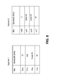
- FIG. 8 shows yet another bitmap format for indicating which channels are to be used in the current transmission, according to an embodiment of the invention.
- FIG. 9 shows a more detailed view of the bitmap of FIG. 8 , according to an embodiment of the invention.
- FIG. 10 shows still another bitmap format for indicating which channels are to be used in the current transmission, according to an embodiment of the invention.
- FIG. 11 shows a flow diagram of a method of allocating and selecting channels for subsequent communication, according to an embodiment of the invention
- references to “one embodiment”, “an embodiment”, “example embodiment”, “various embodiments”, etc. indicate that the embodiment(s) of the invention so described may include particular features, structures, or characteristics, but not every embodiment necessarily includes the particular features, structures, or characteristics. Further, some embodiments may have some, all, or none of the features described for other embodiments.
- Coupled is used to indicate that two or more elements are in direct physical or electrical contact with each other.
- Connected is used to indicate that two or more elements are in direct physical or electrical contact with each other.
- Connected is used to indicate that two or more elements are in direct physical or electrical contact with each other.
- Connected is used to indicate that two or more elements are in direct physical or electrical contact with each other.
- Coupled is used to indicate that two or more elements co-operate or interact with each other, but they may or may not be in direct physical or electrical contact.
- Various embodiments of the invention may be implemented in one or any combination of hardware, firmware, and software.
- the invention may also be implemented as instructions contained in or on a computer-readable medium, which may be read and executed by one or more processors to enable performance of the operations described herein.
- a computer-readable medium may include any mechanism for storing information in a form readable by one or more computers.
- a computer-readable medium may include a tangible storage medium, such as but not limited to read only memory (ROM); random access memory (RAM); magnetic disk storage media; optical storage media; a flash memory device, etc.
- wireless may be used to describe circuits, devices, systems, methods, techniques, communications channels, etc., that communicate data by using modulated electromagnetic radiation through a non-solid medium. The term does not imply that the associated devices do not contain any wires, although in some embodiments they might not.
- a wireless device may comprise at least one antenna, at least one radio, and at least one processor, where the radio's transmitter transmits signals through the antenna that represent data and the radio's receiver receives signals through the antenna that represent data, while the processor may process the data to be transmitted and the data that has been received. The processor may also process other data which is neither transmitted nor received.
- Network controller is intended to cover devices that schedule and control, at least partially, wireless communications by other devices in the network.
- Network controllers may also be known as base stations (BS), access points (AP), central points (CP), or any other term that may arise to describe the functionality of a network controller.
- mobile device is intended to cover those devices whose wireless communications are at least partially scheduled and controlled by the network controller.
- Mobile devices may also be known as mobile nodes, STA's, subscriber stations (SS), user equipment (UE), or any other term that may arise to describe the functionality of a mobile device. Mobile devices may generally move during such communications, but movement is not required.
- a ‘narrow’ channel is a wireless communications channel having a pre-defined bandwidth in the frequency spectrum
- a ‘wide’ channel is a channel having the combined portions of the frequency spectrum occupied by multiple ones of these narrow channels.
- these narrow channels don't have to be contiguous, i.e., two narrow channels that are included in the wide channel may be separated by one or more narrow channels that are not included in the wide channel.
- the narrow channels may frequently be described herein as having a 20 MHz bandwidth, while the wide channels may be described as having a bandwidth that is an integer multiple of 20 MHz, but other embodiments may use narrow-channel bandwidths other than 20 MHz.
- ‘available’ channels are those channels that are permitted for use within the network. This may be defined by industry standards, for example, or by the NC for the collective use by the devices in its network. As used in this document, ‘allocated’ channels are those available channels that the NC has specified for use by a particular MD, and may be changed from time to time by the NC.
- various embodiments of the invention may enable a NC to indicate to a MD which of those narrow channels the MD may use in subsequent wide-channel communication, and may also enable a way to specify which of those indicated channels are actually being used in those subsequent communications.
- FIG. 1 shows a wireless network, according to an embodiment of the invention.
- NC 110 is shown communicating wirelessly with mobile device 120 , through their antennas 115 and 125 , respectively.
- Each illustrated antenna 115 , 125 may be a single antenna or multiple antennas, depending on the technology being used.
- MD mobile device
- FIG. 2 shows an information element (IE) for indicating which narrow channels may be combined to form a wide channel, according to an embodiment of the invention.
- IE information element
- the IE may be located in the body of a MAC frame, but other embodiments may place it elsewhere.
- This particular IE may be included in a larger transmission from the NC to a MD, to indicate to that MD which narrow channels the MD may use for subsequent wide channel communications.
- FIG. 2 shows a particular arrangement of fields in the IE, but other arrangements may also be used.
- the MD may choose to use all or only some of the indicated narrow channels in its subsequent wide channel communications, and may change that choice as often as it is possible to specify such a change.
- the IE may begin with the standard Element ID field, which indicates what type of IE this is (in this case, an IE that defines which narrow channels may be included in the wide channel), followed by the Length field, which indicates how much of the following bit stream is a part of this IE.
- the next field shows how many non-primary channels are indicated by this IE (three are shown in FIG. 2 ).
- the primary channel is the narrow channel that a device may use when the other narrow channels are still unknown, and can be used in both wide- and narrow-channel communication.
- the non-primary channels are therefore the remaining narrow channels that may be combined with the primary channel to construct the wide channel defined by this IE.
- the primary channel is always used in communications, either by itself or in combination with the non-primary channels.
- the primary channel may have been previously defined and identified through means that are beyond the scope of this document.
- the rest of the illustrated IE identifies the non-primary channels in multiple Channel Number fields, with each one identifying a specific non-primary narrow channel.
- the IE may also contain fields to indicate the regulatory class. In the illustrated example there is a separate regulatory class field associated with, and preceding, each channel number field, but other embodiments may differ (e.g., a single regulatory class may be used for all the indicated narrow channels, thus requiring only a single field to define that regulatory class).
- the regulatory class may specify the bandwidth of the narrow channel. This is especially useful in environments in which the bandwidth of the narrow channels is not the same throughout all the available narrow channels.
- the IE contains no information on the primary channel (since it is already known), but other embodiments may include information on the primary channel. In other embodiments, the IE may also contain other information not shown here.
- FIG. 3 shows a portion of a transmission, according to an embodiment of the invention.
- a previous communication has specified three non-primary narrow channels that can be used in combination with a primary fourth channel to communicate over a wide channel, and these four 20 MHz channels are indicated by the four illustrated rows.
- these narrow channels are contiguous, although this assumption is not required for an understanding of the drawing.
- the format shown in FIG. 3 may be part of a preamble of a larger transmission.
- the receiving device may not know which of the narrow channels the transmitting device is going to use.
- the transmitting device may transmit the first few fields in parallel on each of the four narrow channels (including the primary channel). This should guarantee that no matter which narrow channel the receiving device monitors, it can correctly receive these fields. It also provides a backup signal in case one of the narrow channels suffers from interference, distortion, or weak signal strength.
- the first two fields are the Short Training Field (STF) and the Long Training Field (LTF), which the receiving device will need to properly acquire and synchronize on the signal.
- the next two fields may provide information on how the remaining transmission is going to use the indicated channels. In this case, they indicate the subsequent signals will be modulated into an 80 MHz wide channel. A repeat of the training may then be done on this new 80 MHz wide channel. Use of the indicated wide channel may then continue for the remainder of the packet, frame, or whatever unit of communication it applies to.
- the illustrated fields include prefixes to indicate legacy protocols (L) and very high throughput (VHT) protocols to accommodate both older legacy devices and newer high throughput devices, but these protocols may be different than shown, depending on the capabilities of the system.
- FIG. 4 shows a portion of a transmission, according to another embodiment of the invention.
- the primary difference between FIG. 3 and FIG. 4 is that the transmitting device has chosen to use only two of the four allocated narrow channels, to create a 40 MHz wide channel for its communication.
- the primary channel ‘P’ (the second narrow channel in this example) is included in the two narrow channels that are selected for use.
- FIGS. 5A and 5B show bitmap formats for indicating which of the allocated narrow channels are to be used in the current transmission, according to an embodiment of the invention.
- the bitmap is located in the VHT-SIG field of the preamble (e.g., as shown in FIGS. 3 and 4 ), but other embodiments may place it elsewhere.
- the NC may use the bitmap format to specify which of those allocated channels it is using in its current transmission.
- the NC may indicate which of the previously-allocated channels it is using in its current transmission to the MD.
- FIGS. 5A, 5B provide a compact method of indicating which narrow channels may be combined into a wide channel. Narrow channels with a width of 20 MHz are shown, but other channel widths may be used instead.
- the maximum wide-channel width in the network is 80 MHz, only two bits may be needed to specify whether the channels being used by the transmitting device are to cover 20, 40, 60, or 80 MHz, as shown in FIG. 5A . Since only contiguous channels are indicated with this format, knowing the primary channel and the number of contiguous non-primary channels is sufficient to define which channels they are. Three bits may be sufficient to expand this up to 100, 120, 140, or 160 MHz, as shown in FIG. 5B . Additional bits may expand this to even larger wide channels.
- FIG. 6 shows another bitmap format for indicating which of the allocated narrow channels are to be used in the current transmission, according to an embodiment of the invention.
- each bit in the map represents a particular narrow channel. For example, if that bit is a ‘1’, the associated channel is selected, while a value of ‘0’ indicates that channel is not selected. (Of course, the opposite polarities may be used instead.)
- there are 24 bits to represent 24 narrow channels and the channels are labeled with channel numbers 36 through 1 65 in increments of 4, which is a common method of numbering channels under some versions of the industry standard IEEE 802.11.
- channel numbers 36 through 1 65 is a common method of numbering channels under some versions of the industry standard IEEE 802.11
- other numbers of bits and other channel numbering conventions may also be used with this format.
- This format is extremely flexible, since it does not require contiguous channels, and all the channels in the spectrum are represented (even those that were not allocated). However, using that many bits in every preamble may be unacceptable in some environments.
- FIG. 7 shows a modified version of the bitmap of FIG. 6 , according to an embodiment of the invention.
- each bit is associated with one of the channels permitted under the current regulations and industry standards, while in FIG. 7 each bit is associated with one of the channels previously allocated by the NC.
- the first bit of FIG. 7 is associated with the first channel indicated in the IE of FIG. 2 (channel 44 ).
- the second and third bits of FIG. 7 are associated with the second and third channels indicated in the IE (channels 149 and 157, respectively).
- pre-defined narrow channels have had a width of 20 MHz, and wider channels were constructed by combining these 20 MHz channels on the fly.
- certain specific pairs of adjacent 20 MHz channels are being pre-defined as 40 MHz channels.
- 40 MHz channels may be pre-defined by an industry standard as consisting of any of these two pairs of adjacent 20 MHz channels: 36/40, 44/48, 52/56, 60/64, 100/104, 108/112, 116/120, 124/128, 132/136, 149/153, 157/161.
- Certain regulatory classes may specify that a narrow channel has a 40 MHz width and whether the adjacent channel is up or down from the primary 20 MHz channel, so the IE of FIG.
- each pre-defined 40 MHz channel may be specified with a single bit in a bitmap.
- the bitmaps of FIGS. 5A, 5B, 6, and 7 may be modified in such cases by simply replacing each 20 MHz channel with a 40 MHz channel, and/or by replacing each 20 MHz bandwidth with a 40 MHz bandwidth.
- the available channels may be divided into segments, and the selected channels in each segment may be indicated separately.
- the selected narrow channels may have any pre-determined width, such as 20 MHz, 40 MHz, or other width.
- the pre-defined 20 MHz channels 36, 40, 44, and 48 may be placed in Segment 1, and channels 149, 153, 157, and 161 may be placed in Segment 2.
- the selection may be a bit-to-channel correspondence (similar to FIGS. 6 and 7 ) or a total-bit-value to total-bandwidth correspondence (similar to FIGS. 5A and 5B ).
- FIGS. 5A and 5B may be a bit-to-channel correspondence.
- other embodiments may use more than two segments, and/or more that two bits per segment without deviating from the basic concept.
- FIG. 8 shows yet another bitmap format for indicating which channels are to be used in the current transmission, according to an embodiment of the invention.
- the first two bits of a four-bit entry may indicate the selected channels in Segment 1 and the next two bits of that entry may indicate the selected channels in Segment 2.
- a value of ‘00’ in the first two bits may select the primary channel only, a value of ‘10’ may selects the lower 40 MHz of channels in Segment 1 (including the primary channel), while a value of ‘11’ may select all 80 MHz of channels in Segment 1.
- a value of 00 in the next two bits may select none of the channels in Segment 2, while a value of ‘01’ may select the upper 40 MHz of channels, a value of ‘10’ may select the lower 40 MHz of channels, and a value of ‘11’ may select both the upper and lower 40 MHz of channels for a total of 80 MHz in Segment 2.
- each individual ‘1’ bit indicates the selection of a 40 MHz channel that consists of two adjacent 20 MHz channels.
- FIG. 9 shows a more detailed view of the bitmap of FIG. 8 , according to an embodiment of the invention.
- channel 36 is the primary 20 MHz channel
- channels 40, 44, and 48 represent the non-primary 20 MHz channels in Segment 1
- channels 149, 153, 157, and 161 represent the non-primary 20 MHz channels in Segment 2.
- each ‘1’ bit selects a 40 MHz combination of two adjacent 20 MHz channels (36/40, 44/48, 149/153, or 157/161), while the value ‘0000’ selects only the 20 MHz primary channel.
- FIG. 10 shows still another bitmap format for indicating which channels are to be used in the current transmission, according to an embodiment of the invention.
- Most of the entries in the previously described bitmaps have been defined in one of two ways: 1) each bit corresponds to a specific narrow channel, or 2) the value of a multi-bit number corresponds to the collective bandwidth of a group of contiguous narrow channels. But in another approach, the value of a multi-bit number in the bitmap may correspond to a particular pre-defined combination of channels, which may have any bandwidth and may be non-contiguous. This approach is extremely flexible in the variety of channels and channel widths that may be indicated with a small multi-bit combination, since those factors are pre-defined and therefore don't need to be defined by the bitmap.
- FIG. 10 shows an example.
- a simple three-bit value can indicate eight different combinations of channels. These channels may have various widths, may be placed in different segments, and may be contiguous or non-contiguous. In such an embodiment, there is no pre-defined correspondence between any particular bit and any particular channel(s), and no internal limit on how many of the available channels may be represented by a particular value.
- each bit may represent a different pre-defined multi-channel combination, and a value containing multiple ‘1’ bits would therefore indicate a larger combination of two or more of the pre-defined channel combinations.
- FIG. 11 shows a flow diagram of a method of allocating and selecting channels for subsequent communication, according to an embodiment of the invention.
- Flow diagram 1100 shows activities by both the NC and an MD in their communications with each other.
- the NC may transmit a message containing information that allocates specific ones of the available narrow channels that may be used in subsequent communications.
- this message may be a beacon, a probe response, or a neighbor report, but other embodiments may differ.
- the information may be contained within an Information Element (IE), as IE's are defined in various industry standards (e.g., such as IEEE 802.11).
- IE Information Element
- the MD When the MD receives the message at 1115 , it may record the list of allocated channels for use in subsequent communications. When ready to transmit back to the NC, the MD may compose the transmission at 1120 , and at 1125 select which of the allocated channels it will use for this transmission. This selection may be based on various factors which are not discussed here in detail. At 1130 the MD may create a bitmap for inclusion in this transmission, with that bitmap indicating which channels it has selected for this transmission. In some embodiments the bitmap may be placed in a SIG field in the preamble of the transmission. At 1135 the MD transmits the message to the NC, which receives it at 1140 .
- the NC may perform the same basic process at 1145 - 1160 that was performed by the MD at 1120 - 1135 . However, at 1150 it may select the same or different channels than were selected by the MD at 1125 . This process of communicating back and forth may continue with the same list of allocated channels at 1115 - 1160 for as long as the NC chooses. However, if the NC chooses to change the list of allocated channels, it may return to 1110 to transmit the new list to the MD, including the information in whatever type of message is deemed suitable.
- the NC may transmit a different list of allocated channels to the MD than the NC will use in its subsequent transmissions to the MD (i.e., the list will be different for NC-to-MD transmissions than for MD-to-NC transmissions).
- the list of allocated channels may be used for direct communications between the MD and another MD, where such peer-to-peer communications are allowed
Landscapes
- Engineering & Computer Science (AREA)
- Signal Processing (AREA)
- Computer Networks & Wireless Communication (AREA)
- Mobile Radio Communication Systems (AREA)
- Micro-Organisms Or Cultivation Processes Thereof (AREA)
Abstract
In a wireless communications network in which a device may simultaneously use multiple 20 MHz channels for communicating with another network device, various embodiments of the invention provide a way for a network controller to indicate to a mobile device which channels are to be used in communicating with the mobile device.
Description
This a application is a continuation of, claims the benefit of and priority to, U.S. patent application Ser. No. 13/209,077 filed Aug. 12, 2011, entitled “BANDWIDTH AND CHANNEL NOTIFICATION FOR WIDE-CHANNEL WIRELESS COMMUNICATION,” a divisional of U.S. patent application Ser. No. 12/660,224, filed Feb. 23, 2010, entitled “BANDWIDTH AND CHANNEL NOTIFICATION FOR WIDE-CHANNEL WIRELESS COMMUNICATION,” issued as U.S. Pat. No. 8,417,253, the subject matter of both of the above are hereby incorporated by reference in their entirety.
In some conventional networks, the devices may communicate with each other over multiple channels, each having a defined channel width. For example, some standards define a series of channels, each having a center frequency spaced 20 MHz from the next adjacent channel. The defined bandwidth of each channel is therefore approximately 20 MHz, which can be used in wireless communications between devices. A later standard defined a channel bandwidth of 40 MHz. To preserve backward compatibility, each 40 MHz channel may be achieved by combining two adjacent 20 MHz channels. It's a comparatively simple matter for a network controller to assign a 40 MHz channel when it only has to indicate a primary 20 MHz channel and the next adjacent channel up (or down). But recent proposals have been made to expand the channel bandwidth even further to provide a channel width of 80 MHz, 160 MHz, or any other multiple of 20 MHz greater than 40 MHz. Further, some of the indicated 20 MHz channels might not even be adjacent to any of the other 20 MHz channels. Conventional techniques for allocating 20 MHz channels to achieve a channel bandwidth greater than 40 MHz are not adequate for this scenario.
Some embodiments of the invention may be understood by referring to the following description and accompanying drawings that are used to illustrate embodiments of the invention. In the drawings:
In the following description, numerous specific details are set forth. However, it is understood that embodiments of the invention may be practiced without these specific details. In other instances, well-known circuits, structures and techniques have not been shown in detail in order not to obscure an understanding of this description.
References to “one embodiment”, “an embodiment”, “example embodiment”, “various embodiments”, etc., indicate that the embodiment(s) of the invention so described may include particular features, structures, or characteristics, but not every embodiment necessarily includes the particular features, structures, or characteristics. Further, some embodiments may have some, all, or none of the features described for other embodiments.
In the following description and claims, the terms “coupled” and “connected,” along with their derivatives, may be used. It should be understood that these terms are not intended as synonyms for each other. Rather, in particular embodiments, “connected” is used to indicate that two or more elements are in direct physical or electrical contact with each other. “Coupled” is used to indicate that two or more elements co-operate or interact with each other, but they may or may not be in direct physical or electrical contact.
As used in the claims, unless otherwise specified the use of the ordinal adjectives “first”, “second”, “third”, etc., to describe a common element, merely indicate that different instances of like elements are being referred to, and are not intended to imply that the elements so described must be in a given sequence, either temporally, spatially, in ranking, or in any other manner.
Various embodiments of the invention may be implemented in one or any combination of hardware, firmware, and software. The invention may also be implemented as instructions contained in or on a computer-readable medium, which may be read and executed by one or more processors to enable performance of the operations described herein. A computer-readable medium may include any mechanism for storing information in a form readable by one or more computers. For example, a computer-readable medium may include a tangible storage medium, such as but not limited to read only memory (ROM); random access memory (RAM); magnetic disk storage media; optical storage media; a flash memory device, etc.
The term “wireless” may be used to describe circuits, devices, systems, methods, techniques, communications channels, etc., that communicate data by using modulated electromagnetic radiation through a non-solid medium. The term does not imply that the associated devices do not contain any wires, although in some embodiments they might not. A wireless device may comprise at least one antenna, at least one radio, and at least one processor, where the radio's transmitter transmits signals through the antenna that represent data and the radio's receiver receives signals through the antenna that represent data, while the processor may process the data to be transmitted and the data that has been received. The processor may also process other data which is neither transmitted nor received.
As used within this document, the term “network controller” (NC) is intended to cover devices that schedule and control, at least partially, wireless communications by other devices in the network. Network controllers may also be known as base stations (BS), access points (AP), central points (CP), or any other term that may arise to describe the functionality of a network controller.
As used within this document, the term “mobile device” (MD) is intended to cover those devices whose wireless communications are at least partially scheduled and controlled by the network controller. Mobile devices may also be known as mobile nodes, STA's, subscriber stations (SS), user equipment (UE), or any other term that may arise to describe the functionality of a mobile device. Mobile devices may generally move during such communications, but movement is not required.
As used in this document, a ‘narrow’ channel is a wireless communications channel having a pre-defined bandwidth in the frequency spectrum, while a ‘wide’ channel is a channel having the combined portions of the frequency spectrum occupied by multiple ones of these narrow channels. In some embodiments, these narrow channels don't have to be contiguous, i.e., two narrow channels that are included in the wide channel may be separated by one or more narrow channels that are not included in the wide channel. For simplicity of description, the narrow channels may frequently be described herein as having a 20 MHz bandwidth, while the wide channels may be described as having a bandwidth that is an integer multiple of 20 MHz, but other embodiments may use narrow-channel bandwidths other than 20 MHz. As used in this document, ‘available’ channels are those channels that are permitted for use within the network. This may be defined by industry standards, for example, or by the NC for the collective use by the devices in its network. As used in this document, ‘allocated’ channels are those available channels that the NC has specified for use by a particular MD, and may be changed from time to time by the NC.
In a wireless communications network in which a wide channel can be defined by combining multiple narrow channels, various embodiments of the invention may enable a NC to indicate to a MD which of those narrow channels the MD may use in subsequent wide-channel communication, and may also enable a way to specify which of those indicated channels are actually being used in those subsequent communications.
The IE may begin with the standard Element ID field, which indicates what type of IE this is (in this case, an IE that defines which narrow channels may be included in the wide channel), followed by the Length field, which indicates how much of the following bit stream is a part of this IE. The next field shows how many non-primary channels are indicated by this IE (three are shown in FIG. 2 ). The primary channel is the narrow channel that a device may use when the other narrow channels are still unknown, and can be used in both wide- and narrow-channel communication. The non-primary channels are therefore the remaining narrow channels that may be combined with the primary channel to construct the wide channel defined by this IE. In some embodiments, the primary channel is always used in communications, either by itself or in combination with the non-primary channels. The primary channel may have been previously defined and identified through means that are beyond the scope of this document.
The rest of the illustrated IE identifies the non-primary channels in multiple Channel Number fields, with each one identifying a specific non-primary narrow channel. The IE may also contain fields to indicate the regulatory class. In the illustrated example there is a separate regulatory class field associated with, and preceding, each channel number field, but other embodiments may differ (e.g., a single regulatory class may be used for all the indicated narrow channels, thus requiring only a single field to define that regulatory class). Among other things, the regulatory class may specify the bandwidth of the narrow channel. This is especially useful in environments in which the bandwidth of the narrow channels is not the same throughout all the available narrow channels. In the illustrated example, the IE contains no information on the primary channel (since it is already known), but other embodiments may include information on the primary channel. In other embodiments, the IE may also contain other information not shown here.
The format shown in FIG. 3 may be part of a preamble of a larger transmission. At the beginning of this transmission, the receiving device may not know which of the narrow channels the transmitting device is going to use. To make sure the preamble is received, the transmitting device may transmit the first few fields in parallel on each of the four narrow channels (including the primary channel). This should guarantee that no matter which narrow channel the receiving device monitors, it can correctly receive these fields. It also provides a backup signal in case one of the narrow channels suffers from interference, distortion, or weak signal strength.
The first two fields are the Short Training Field (STF) and the Long Training Field (LTF), which the receiving device will need to properly acquire and synchronize on the signal. The next two fields (SIG) may provide information on how the remaining transmission is going to use the indicated channels. In this case, they indicate the subsequent signals will be modulated into an 80 MHz wide channel. A repeat of the training may then be done on this new 80 MHz wide channel. Use of the indicated wide channel may then continue for the remainder of the packet, frame, or whatever unit of communication it applies to. The illustrated fields include prefixes to indicate legacy protocols (L) and very high throughput (VHT) protocols to accommodate both older legacy devices and newer high throughput devices, but these protocols may be different than shown, depending on the capabilities of the system.
In the case where the channels are all contiguous and the primary channel is known to be the highest (or lowest) narrow channel, the formats of FIGS. 5A, 5B provide a compact method of indicating which narrow channels may be combined into a wide channel. Narrow channels with a width of 20 MHz are shown, but other channel widths may be used instead.
If the maximum wide-channel width in the network is 80 MHz, only two bits may be needed to specify whether the channels being used by the transmitting device are to cover 20, 40, 60, or 80 MHz, as shown in FIG. 5A . Since only contiguous channels are indicated with this format, knowing the primary channel and the number of contiguous non-primary channels is sufficient to define which channels they are. Three bits may be sufficient to expand this up to 100, 120, 140, or 160 MHz, as shown in FIG. 5B . Additional bits may expand this to even larger wide channels.
In earlier industry standards, pre-defined narrow channels have had a width of 20 MHz, and wider channels were constructed by combining these 20 MHz channels on the fly. However, with the increased use of channels having a width of 40 MHz, certain specific pairs of adjacent 20 MHz channels are being pre-defined as 40 MHz channels. For example, 40 MHz channels may be pre-defined by an industry standard as consisting of any of these two pairs of adjacent 20 MHz channels: 36/40, 44/48, 52/56, 60/64, 100/104, 108/112, 116/120, 124/128, 132/136, 149/153, 157/161. Certain regulatory classes may specify that a narrow channel has a 40 MHz width and whether the adjacent channel is up or down from the primary 20 MHz channel, so the IE of FIG. 2 may be used to indicate these without further definition in the communication itself. In such cases, it is possible to specify each pre-defined 40 MHz channel with a single bit in a bitmap. The bitmaps of FIGS. 5A, 5B, 6, and 7 may be modified in such cases by simply replacing each 20 MHz channel with a 40 MHz channel, and/or by replacing each 20 MHz bandwidth with a 40 MHz bandwidth.
In some network definitions, the available channels may be divided into segments, and the selected channels in each segment may be indicated separately. The selected narrow channels may have any pre-determined width, such as 20 MHz, 40 MHz, or other width. For example, the pre-defined 20 MHz channels 36, 40, 44, and 48 may be placed in Segment 1, and channels 149, 153, 157, and 161 may be placed in Segment 2. The selection may be a bit-to-channel correspondence (similar to FIGS. 6 and 7 ) or a total-bit-value to total-bandwidth correspondence (similar to FIGS. 5A and 5B ). Of course, other embodiments may use more than two segments, and/or more that two bits per segment without deviating from the basic concept.
In still another variation, each bit may represent a different pre-defined multi-channel combination, and a value containing multiple ‘1’ bits would therefore indicate a larger combination of two or more of the pre-defined channel combinations.
When the MD receives the message at 1115, it may record the list of allocated channels for use in subsequent communications. When ready to transmit back to the NC, the MD may compose the transmission at 1120, and at 1125 select which of the allocated channels it will use for this transmission. This selection may be based on various factors which are not discussed here in detail. At 1130 the MD may create a bitmap for inclusion in this transmission, with that bitmap indicating which channels it has selected for this transmission. In some embodiments the bitmap may be placed in a SIG field in the preamble of the transmission. At 1135 the MD transmits the message to the NC, which receives it at 1140.
If the NC chooses to use the same list of allocated channels in its communications with this MD, it may perform the same basic process at 1145-1160 that was performed by the MD at 1120-1135. However, at 1150 it may select the same or different channels than were selected by the MD at 1125. This process of communicating back and forth may continue with the same list of allocated channels at 1115-1160 for as long as the NC chooses. However, if the NC chooses to change the list of allocated channels, it may return to 1110 to transmit the new list to the MD, including the information in whatever type of message is deemed suitable.
In some embodiments, the NC may transmit a different list of allocated channels to the MD than the NC will use in its subsequent transmissions to the MD (i.e., the list will be different for NC-to-MD transmissions than for MD-to-NC transmissions). In some embodiments, the list of allocated channels may be used for direct communications between the MD and another MD, where such peer-to-peer communications are allowed
The foregoing description is intended to be illustrative and not limiting. Variations will occur to those of skill in the art. Those variations are intended to be included in the various embodiments of the invention, which are limited only by the scope of the following claims.
Claims (6)
1. An apparatus, comprising:
at least one antenna;
a processor to:
identify a plurality of allocated 20 MHz channels based on information comprised in a first message received from an access point (AP);
select, from among the plurality of allocated 20 MHz channels, two or more 20 MHz channels to be combined to form a wide channel; and
generate a second message for transmission over the wide channel, the second message to comprise a multi-bit bitmap indicating the selected two or more 20 MHz channels; and
a radio coupled to the processor and the at least one antenna, the radio to transmit the second message over the wide channel.
2. A method, comprising:
identifying, by a processor of a station (STA), a plurality of allocated 20 MHz channels based on information comprised in a first message received from an access point (AP);
selecting, from among the plurality of allocated 20 MHz channels, two or more 20 MHz channels to be combined to form a wide channel; and
transmitting a second message over the wide channel, the second message to comprise a multi-bit bitmap indicating the selected two or more 20 MHz channels.
3. A non-transitory computer-readable storage medium containing instructions that, when executed by one or more processors, cause a station (STA) to:
identify a plurality of allocated 20 MHz channels based on information comprised in a first message received from an access point (AP);
select, from among the plurality of allocated 20 MHz channels, two or more 20 MHz channels to be combined to form a wide channel; and
transmit a second message over the wide channel, the second message to comprise a multi-bit bitmap indicating the selected two or more 20 MHz channels.
4. An apparatus, comprising:
at least one antenna;
a radio coupled to the at least one antenna; and
a processor coupled to the radio, the processor to:
generate a first message for transmission to a station (STA), the first message to comprise information indicating a plurality of allocated 20 MHz channels;
based on a multi-bit bitmap comprised in a second message received from the STA, identify two or more 20 MHz channels to be combined to form a wide channel, each one of the two or more 20 MHz channels to be comprised among the plurality of allocated 20 MHz channels; and
process data comprised in a data portion of the second message, the data portion to be received via the wide channel.
5. A method, comprising:
generating, by a processor of an access point (AP), a first message for transmission to a station (STA), the first message to comprise information indicating a plurality of allocated 20 MHz channels;
based on a multi-bit bitmap comprised in a second message received from the STA, identifying two or more 20 MHz channels to be combined to form a wide channel, each one of the two or more 20 MHz channels to be comprised among the plurality of allocated 20 MHz channels;
receiving a data portion of the second message via the wide channel; and
processing data comprised in the data portion of the second message.
6. A non-transitory computer-readable storage medium containing instructions that, when executed by one or more processors, cause an access point (AP) to:
generate a first message for transmission to a station (STA), the first message to comprise information indicating a plurality of allocated 20 MHz channels;
based on a multi-bit bitmap comprised in a second message received from the STA, identify two or more 20 MHz channels to be combined to form a wide channel, each one of the two or more 20 MHz channels to be comprised among the plurality of allocated 20 MHz channels;
receive a data portion of the second message via the wide channel; and
process data comprised in the data portion of the second message.
Priority Applications (1)
| Application Number | Priority Date | Filing Date | Title |
|---|---|---|---|
| US14/881,044 US10129879B2 (en) | 2010-02-23 | 2015-10-12 | Bandwidth and channel notification for wide-channel wireless communication |
Applications Claiming Priority (3)
| Application Number | Priority Date | Filing Date | Title |
|---|---|---|---|
| US12/660,224 US8417253B2 (en) | 2010-02-23 | 2010-02-23 | Bandwidth and channel notification for wide-channel wireless communication |
| US13/209,077 US9160499B2 (en) | 2010-02-23 | 2011-08-12 | Bandwidth and channel notification for wide-channel wireless communication |
| US14/881,044 US10129879B2 (en) | 2010-02-23 | 2015-10-12 | Bandwidth and channel notification for wide-channel wireless communication |
Related Parent Applications (1)
| Application Number | Title | Priority Date | Filing Date |
|---|---|---|---|
| US13/209,077 Continuation US9160499B2 (en) | 2010-02-23 | 2011-08-12 | Bandwidth and channel notification for wide-channel wireless communication |
Publications (2)
| Publication Number | Publication Date |
|---|---|
| US20160270078A1 US20160270078A1 (en) | 2016-09-15 |
| US10129879B2 true US10129879B2 (en) | 2018-11-13 |
Family
ID=44476933
Family Applications (3)
| Application Number | Title | Priority Date | Filing Date |
|---|---|---|---|
| US12/660,224 Active 2030-11-22 US8417253B2 (en) | 2010-02-23 | 2010-02-23 | Bandwidth and channel notification for wide-channel wireless communication |
| US13/209,077 Active US9160499B2 (en) | 2010-02-23 | 2011-08-12 | Bandwidth and channel notification for wide-channel wireless communication |
| US14/881,044 Active US10129879B2 (en) | 2010-02-23 | 2015-10-12 | Bandwidth and channel notification for wide-channel wireless communication |
Family Applications Before (2)
| Application Number | Title | Priority Date | Filing Date |
|---|---|---|---|
| US12/660,224 Active 2030-11-22 US8417253B2 (en) | 2010-02-23 | 2010-02-23 | Bandwidth and channel notification for wide-channel wireless communication |
| US13/209,077 Active US9160499B2 (en) | 2010-02-23 | 2011-08-12 | Bandwidth and channel notification for wide-channel wireless communication |
Country Status (7)
| Country | Link |
|---|---|
| US (3) | US8417253B2 (en) |
| EP (3) | EP2539433A4 (en) |
| JP (4) | JP5372038B2 (en) |
| KR (1) | KR101404372B1 (en) |
| CN (3) | CN102906246A (en) |
| BR (1) | BR112012020712B1 (en) |
| WO (2) | WO2011106043A2 (en) |
Families Citing this family (34)
| Publication number | Priority date | Publication date | Assignee | Title |
|---|---|---|---|---|
| US20100279178A1 (en) | 2009-02-23 | 2010-11-04 | Barkeloo Jason E | Microbial fuel cell |
| US8417253B2 (en) * | 2010-02-23 | 2013-04-09 | Intel Corporation | Bandwidth and channel notification for wide-channel wireless communication |
| KR101621103B1 (en) | 2010-02-26 | 2016-05-16 | 엘지전자 주식회사 | Method and apparatus of allocating a transmission channel in wireless local area network system |
| ES3016813T3 (en) * | 2010-03-11 | 2025-05-09 | Electronics & Telecommunications Res Inst | Method and apparatus for transceiving data in a mimo system |
| EP2547002B1 (en) | 2010-03-12 | 2015-02-25 | Electronics and Telecommunications Research Institute | Method and apparatus for transmitting and receiving data in a mimo system |
| US9247541B2 (en) | 2010-09-16 | 2016-01-26 | Qualcomm Incorporated | Selecting frequency bands for transmitting data packets |
| US9160503B2 (en) * | 2011-03-04 | 2015-10-13 | Qualcomm Incorporated | Method and apparatus supporting improved wide bandwidth transmissions |
| US10021599B2 (en) * | 2011-09-20 | 2018-07-10 | Qualcomm Incorporated | Channel and bandwidth switch procedures for wireless networks |
| WO2014145346A2 (en) * | 2013-03-15 | 2014-09-18 | Bacterial Robotics, Llc | Compositions, systems and methods for protecting genetically modified organisms from unauthorized use or release into the environment |
| CN103215201B (en) * | 2013-03-19 | 2014-09-10 | 华南理工大学 | Klebsiella oxytoca and its application in bioelectricity production |
| CN103145240B (en) * | 2013-03-22 | 2015-01-07 | 湖南大学 | Synchronous electricity generating method and device for anaerobic biological treatment of high concentrated organic wastewater |
| CN103337651B (en) * | 2013-06-14 | 2015-08-26 | 国家电网公司 | A kind of Biological-agent fuel cell |
| CN103337652B (en) * | 2013-06-14 | 2015-09-02 | 国家电网公司 | A kind of fuel cell |
| US9655119B2 (en) * | 2013-11-07 | 2017-05-16 | Qualcomm Incorporated | Primary channel determination in wireless networks |
| US9668169B2 (en) | 2014-01-09 | 2017-05-30 | Qualcomm Incorporated | Bandwidth indication in a frame |
| EP3135067B1 (en) * | 2014-04-21 | 2021-02-24 | Kabushiki Kaisha Toshiba | A wireless communication device and method |
| JP6454722B2 (en) * | 2014-04-21 | 2019-01-16 | 株式会社東芝 | Wireless communication apparatus and wireless communication method |
| CN104091962B (en) * | 2014-06-26 | 2016-03-09 | 扬州大学 | The method of automatic structure stable electrical catalysis bacterial biof iotalm |
| CN104332645B (en) * | 2014-09-01 | 2017-08-11 | 山东科技大学 | A kind of microbiological fuel cell for handling leaded sewage |
| KR101946375B1 (en) * | 2014-09-28 | 2019-02-11 | 엘지전자 주식회사 | Method for supporting flexible resource allocation in wireless communication system, and apparatus therefor |
| US10517100B2 (en) | 2014-12-08 | 2019-12-24 | Kabushiki Kaisha Toshiba | Radio resource allocation in a wireless communication network |
| CN104701562B (en) * | 2015-03-03 | 2017-06-13 | 北京师范大学-香港浸会大学联合国际学院 | The biological straight drive generating battery of microalgae |
| WO2016145939A1 (en) * | 2015-03-19 | 2016-09-22 | 华为技术有限公司 | Channel indication method and device |
| CN105552466B (en) * | 2015-11-05 | 2018-01-05 | 兰州大学 | A kind of p-nitrophenol concentration detection method based on microbiological fuel cell |
| CN106409538B (en) * | 2016-10-20 | 2018-09-28 | 青岛大学 | A kind of integrated device and preparation method thereof of biomass energy conversion and storage |
| US20180227734A1 (en) * | 2017-02-07 | 2018-08-09 | Electronics And Telecommunications Research Institute | Method and apparatus for proximity communications using channel aggregation |
| CN109378508A (en) * | 2018-09-30 | 2019-02-22 | 天津大学 | A single-chamber microbial fuel cell adding degradable bacteria and using method thereof |
| CN109608292B (en) * | 2018-12-27 | 2021-11-30 | 中国科学院生态环境研究中心 | Nitrogen fertilizer composition and application thereof |
| CN109921071A (en) * | 2019-01-30 | 2019-06-21 | 华中科技大学 | A method of improving microbiological fuel cell sensing capabilities |
| WO2021010606A1 (en) * | 2019-07-12 | 2021-01-21 | 엘지전자 주식회사 | Capability negotiation in multilink |
| CN110767960B (en) * | 2019-11-15 | 2021-01-01 | 广东轻工职业技术学院 | Flexible device integrated with microbial fuel cell and hybrid supercapacitor, preparation method and application |
| CN118027162A (en) * | 2022-01-07 | 2024-05-14 | 深圳市灵蛛科技有限公司 | Polypeptide, polynucleotide encoding polypeptide, construct, expression system and battery thereof |
| CN114921396B (en) * | 2022-05-31 | 2023-10-31 | 中国地质大学(武汉) | Geobacillus electrogenesis, construction method and application |
| CN115851800A (en) * | 2022-09-20 | 2023-03-28 | 天津大学 | Method for improving electronic transmission capacity of Shewanella |
Citations (10)
| Publication number | Priority date | Publication date | Assignee | Title |
|---|---|---|---|---|
| WO2001041380A2 (en) | 1999-11-30 | 2001-06-07 | Siemens Technology-To-Business Center, Llc | Characteristic routing |
| JP2004349972A (en) | 2003-05-21 | 2004-12-09 | Kobe Steel Ltd | Communication system, communication terminal, and management server |
| US20060182017A1 (en) | 2005-02-16 | 2006-08-17 | Hansen Christopher J | Method and system for compromise greenfield preambles for 802.11n |
| US20080101281A1 (en) | 2006-10-27 | 2008-05-01 | Motorola, Inc. | Method and apparatus for reducing overhead for signaling |
| US20090036063A1 (en) * | 2006-12-04 | 2009-02-05 | Interdigital Technology Corporation | Distributed reservation protocol for enabling multi-band transmission in next generation ultra wide band technology |
| JP2009037468A (en) | 2007-08-02 | 2009-02-19 | Hitachi Information & Communication Engineering Ltd | Vehicle detection system and method |
| US20090258603A1 (en) * | 2008-04-09 | 2009-10-15 | Nokia Corporation | Distributed multi-channel cognitive mac protocol |
| US20100040158A1 (en) * | 2008-08-15 | 2010-02-18 | Qualcomm Incorporated | Embedding information in an 802.11 signal field |
| US8417253B2 (en) * | 2010-02-23 | 2013-04-09 | Intel Corporation | Bandwidth and channel notification for wide-channel wireless communication |
| US8588173B2 (en) | 2008-08-07 | 2013-11-19 | Panasonic Corporation | Frequency band allocation method and transmission device |
Family Cites Families (62)
| Publication number | Priority date | Publication date | Assignee | Title |
|---|---|---|---|---|
| US5276908A (en) | 1990-10-25 | 1994-01-04 | Northern Telecom Limited | Call set-up and spectrum sharing in radio communication on systems with dynamic channel allocation |
| US6542481B2 (en) * | 1998-06-01 | 2003-04-01 | Tantivy Communications, Inc. | Dynamic bandwidth allocation for multiple access communication using session queues |
| US6792616B1 (en) * | 1998-05-01 | 2004-09-14 | Scientific-Atlanta, Inc. | System and method for providing a plurality of programming services in a television system |
| KR100429540B1 (en) | 1998-08-26 | 2004-08-09 | 삼성전자주식회사 | Packet data communication apparatus and method of mobile communication system |
| US6925070B2 (en) * | 2000-07-31 | 2005-08-02 | Ipr Licensing, Inc. | Time-slotted data packets with a preamble |
| CN1255988C (en) * | 2001-11-14 | 2006-05-10 | 松下电器产业株式会社 | Multichannel image procesisng device and method thereof |
| US7899067B2 (en) * | 2002-05-31 | 2011-03-01 | Cisco Technology, Inc. | Method and apparatus for generating and using enhanced tree bitmap data structures in determining a longest prefix match |
| US20040053624A1 (en) * | 2002-09-17 | 2004-03-18 | Frank Ed H. | Method and system for optimal load balancing in a hybrid wired/wireless network |
| US8014374B2 (en) * | 2003-04-07 | 2011-09-06 | Bellow Bellows Llc | System and method for achieving timing compatibility with multi-antenna wireless data protocols |
| US7389096B2 (en) * | 2003-04-07 | 2008-06-17 | Bellow Bellows Llc | Monitoring system using multi-antenna transceivers |
| WO2005002141A1 (en) * | 2003-06-27 | 2005-01-06 | Mitsubishi Denki Kabushiki Kaisha | Transmitter apparatus, receiver apparatus and radio communication apparatus |
| US7349436B2 (en) * | 2003-09-30 | 2008-03-25 | Intel Corporation | Systems and methods for high-throughput wideband wireless local area network communications |
| US9210719B2 (en) * | 2003-11-19 | 2015-12-08 | Koninklijke Philips N.V. | Method for access to a medium by a multi-channel device |
| US7983298B2 (en) * | 2004-10-20 | 2011-07-19 | Qualcomm Incorporated | Multiple frequency band operation in wireless networks |
| TWI514814B (en) | 2004-10-20 | 2015-12-21 | 高通公司 | Multi-band operation in a wireless network |
| US8737494B2 (en) | 2006-01-09 | 2014-05-27 | Broadcom Corporation | Method and system for quantization for a general beamforming matrix in feedback information |
| US7269406B2 (en) * | 2005-05-26 | 2007-09-11 | Intel Corporation | Methods and apparatus for providing information indicative of traffic delay of a wireless link |
| TWI339540B (en) * | 2005-06-09 | 2011-03-21 | Samsung Electronics Co Ltd | Method and apparatus for transmitting data with down compatibility in high throughput wireless network |
| TW200644537A (en) | 2005-06-09 | 2006-12-16 | Samsung Electronics Co Ltd | Method and apparatus for receiving data with down compatibility in high throughput wireless network |
| US20070060162A1 (en) * | 2005-07-21 | 2007-03-15 | Xhafa Ariton E | Methods and apparatus to perform transmission bandwidth detection in wireless local area networks |
| JP2007088517A (en) | 2005-09-16 | 2007-04-05 | Matsushita Electric Ind Co Ltd | Wireless communication apparatus and wireless communication system |
| ES2299969T3 (en) * | 2005-11-10 | 2008-06-01 | Research In Motion Limited | APPARATUS AND METHOD FOR THE SIGNALING OF THE ALLOCATION OF COMMUNICATION RESOURCES IN A BLOCK BASE. |
| KR20070076299A (en) * | 2006-01-18 | 2007-07-24 | 삼성전자주식회사 | Signal transceiving device and method in communication system |
| US8451808B2 (en) * | 2006-02-18 | 2013-05-28 | Intel Corporation | Techniques for 40 megahertz (MHz) channel switching |
| JP4886330B2 (en) * | 2006-03-22 | 2012-02-29 | 株式会社東芝 | Radio communication base station apparatus and radio communication system |
| KR101197521B1 (en) * | 2006-04-24 | 2012-11-09 | 삼성전자주식회사 | Method and apparatus for transmitting/receiving resource allocation information using a bitmap in mobile communication system |
| KR101358424B1 (en) * | 2006-08-10 | 2014-02-17 | 삼성전자주식회사 | Methode and apparatus for transmitting feedback information |
| WO2008018711A2 (en) * | 2006-08-10 | 2008-02-14 | Electronics And Telecommunications Research Institute | Methods for transmitting feedback information |
| US8693407B2 (en) * | 2006-09-11 | 2014-04-08 | Qualcomm Incorporated | Method and apparatus for keep-alive bits transmission |
| US8050200B2 (en) * | 2006-10-04 | 2011-11-01 | Marvell World Trade Ltd. | Opportunistic 40 MHz mode of transmission in wireless transmitters |
| GB0621767D0 (en) * | 2006-11-01 | 2006-12-13 | Nec Corp | Resource allocation |
| US9137672B2 (en) * | 2006-12-09 | 2015-09-15 | Broadcom Corporation | Method and system for coexistence between 20 MHz and 40 MHz overlapping basic service sets (OBSS) in wireless local area networks |
| JP4284354B2 (en) * | 2006-12-26 | 2009-06-24 | 株式会社東芝 | Wireless communication device |
| US7710939B2 (en) * | 2007-02-06 | 2010-05-04 | Samsung Electronics Co., Ltd. | Method and system for power saving in wireless local area communication networks |
| CN104639306B (en) * | 2007-03-19 | 2019-04-16 | Lg电子株式会社 | The method that resources in mobile communication system distributes and transmits/receives resource allocation information |
| US8614985B2 (en) * | 2007-06-15 | 2013-12-24 | Futurewei Technologies, Inc. | Method and apparatus for sharing a group resource in a wireless SDMA system |
| KR101092675B1 (en) * | 2007-07-06 | 2011-12-09 | 엘지전자 주식회사 | Wireless network management method, and station supporting the method |
| GB2451510A (en) * | 2007-08-02 | 2009-02-04 | Nec Corp | Signalling of dynamic allocation of subcarriers in OFDM systems |
| US20100027481A1 (en) * | 2007-08-13 | 2010-02-04 | Nokia Corporation | Common resource signaling for multiple types of allocations |
| US8155482B2 (en) * | 2007-09-12 | 2012-04-10 | Cisco Technology, Inc. | Selecting wider bandwidth channels in a wireless network |
| US8345584B2 (en) * | 2007-09-26 | 2013-01-01 | Lantiq Deutschland Gmbh | Wireless local area network and access point for a wireless local area network |
| US20090092039A1 (en) | 2007-10-03 | 2009-04-09 | Samsung Electronics Co., Ltd. | Method and system for formation and communication of information frames in wireless communication systems |
| US8140095B2 (en) * | 2007-12-04 | 2012-03-20 | Texas Instruments Incorporated | Resolving encoding dependencies for data bursts |
| US7865631B2 (en) * | 2007-12-06 | 2011-01-04 | International Business Machines Corporation | Dynamic logical data channel assignment using time-grouped allocations |
| US8625500B2 (en) * | 2007-12-18 | 2014-01-07 | Nokia Siemens Networks Oy | Enhanced dynamical fast-feedback channel allocations |
| KR101440619B1 (en) * | 2008-01-11 | 2014-09-17 | 엘지전자 주식회사 | Regulatory Class Switching Method in Mesh Networks |
| US20090262688A1 (en) * | 2008-04-22 | 2009-10-22 | Shang-Ho Tsai | Rate adaptation methods for wireless communication apparatus, and wireless communication apparatus for performing wireless communication with rate adaptation |
| CN102027796B (en) * | 2008-05-16 | 2013-12-25 | 皇家飞利浦电子股份有限公司 | Method for allocating transmission resources in a telecommunication system |
| US7929508B1 (en) * | 2008-06-11 | 2011-04-19 | Atheros Communications, Inc. | Radio frequency signal analysis and classification using time-frequency information |
| KR101452504B1 (en) | 2008-06-18 | 2014-10-23 | 엘지전자 주식회사 | Channel access mechanism for Very High Throughput (VHT) wireless local access network system and station supporting the channel access mechanism |
| US7807303B2 (en) * | 2008-06-30 | 2010-10-05 | Xerox Corporation | Microbial fuel cell and method |
| US8577999B2 (en) * | 2009-01-30 | 2013-11-05 | Nokia Corporation | Method for WLAN network and device role activation |
| US8379746B2 (en) * | 2009-02-04 | 2013-02-19 | Yeheskel Bar-Ness | Transmission of orthogonal space time codes |
| US20100279178A1 (en) * | 2009-02-23 | 2010-11-04 | Barkeloo Jason E | Microbial fuel cell |
| US8514883B2 (en) * | 2009-04-24 | 2013-08-20 | Interdigital Patent Holdings, Inc. | Method and apparatus for sending hybrid automatic repeat request feedback for component carrier aggregation |
| US8599804B2 (en) | 2009-08-07 | 2013-12-03 | Broadcom Corporation | Distributed signal field for communications within multiple user, multiple access, and/or MIMO wireless communications |
| US20110038441A1 (en) * | 2009-08-12 | 2011-02-17 | Cambridge Silicon Radio Limited | Transmission mode detection |
| EP2499872B1 (en) * | 2009-11-13 | 2015-01-14 | Marvell World Trade Ltd. | Multi-channel wireless communications |
| DK2499868T3 (en) * | 2009-11-13 | 2014-10-20 | Interdigital Patent Holdings | Method and apparatus for supporting high-throughput management operations in wireless communications |
| US8762543B2 (en) * | 2009-12-15 | 2014-06-24 | Intel Corporation | Method and apparatus for autonomous peer discovery and enhancing link reliability for wireless peer direct links |
| US8634317B1 (en) * | 2010-05-25 | 2014-01-21 | Marvell International Ltd. | Method and apparatus for detecting packets |
| US8619805B2 (en) * | 2011-12-22 | 2013-12-31 | Silver Spring Networks, Inc. | System and method for optimal listen before transmit in wireless communications |
-
2010
- 2010-02-23 US US12/660,224 patent/US8417253B2/en active Active
- 2010-11-04 WO PCT/US2010/055470 patent/WO2011106043A2/en not_active Ceased
- 2010-11-04 EP EP10846788.7A patent/EP2539433A4/en not_active Withdrawn
- 2010-11-04 CN CN2010800663832A patent/CN102906246A/en active Pending
-
2011
- 2011-02-07 JP JP2011024207A patent/JP5372038B2/en active Active
- 2011-02-22 EP EP11747928.7A patent/EP2540126B1/en active Active
- 2011-02-22 BR BR112012020712-1A patent/BR112012020712B1/en active IP Right Grant
- 2011-02-22 EP EP13163070.9A patent/EP2637461B1/en active Active
- 2011-02-22 KR KR1020127021991A patent/KR101404372B1/en active Active
- 2011-02-22 WO PCT/US2011/025717 patent/WO2011106316A2/en not_active Ceased
- 2011-02-23 CN CN201110054047.2A patent/CN102315903B/en active Active
- 2011-02-23 CN CN201210532271.2A patent/CN103067983B/en active Active
- 2011-08-12 US US13/209,077 patent/US9160499B2/en active Active
-
2012
- 2012-12-03 JP JP2012264391A patent/JP2013066223A/en active Pending
-
2015
- 2015-05-22 JP JP2015104588A patent/JP6293092B2/en active Active
- 2015-10-12 US US14/881,044 patent/US10129879B2/en active Active
-
2018
- 2018-02-13 JP JP2018023003A patent/JP2018078661A/en active Pending
Patent Citations (12)
| Publication number | Priority date | Publication date | Assignee | Title |
|---|---|---|---|---|
| WO2001041380A2 (en) | 1999-11-30 | 2001-06-07 | Siemens Technology-To-Business Center, Llc | Characteristic routing |
| JP2003516035A (en) | 1999-11-30 | 2003-05-07 | シーメンス テクノロジー−トゥー−ビジネス センター、リミテッド ライアビリティ カンパニー | Characteristic routing |
| JP2004349972A (en) | 2003-05-21 | 2004-12-09 | Kobe Steel Ltd | Communication system, communication terminal, and management server |
| US20060182017A1 (en) | 2005-02-16 | 2006-08-17 | Hansen Christopher J | Method and system for compromise greenfield preambles for 802.11n |
| US20080101281A1 (en) | 2006-10-27 | 2008-05-01 | Motorola, Inc. | Method and apparatus for reducing overhead for signaling |
| US20090036063A1 (en) * | 2006-12-04 | 2009-02-05 | Interdigital Technology Corporation | Distributed reservation protocol for enabling multi-band transmission in next generation ultra wide band technology |
| JP2009037468A (en) | 2007-08-02 | 2009-02-19 | Hitachi Information & Communication Engineering Ltd | Vehicle detection system and method |
| US20090258603A1 (en) * | 2008-04-09 | 2009-10-15 | Nokia Corporation | Distributed multi-channel cognitive mac protocol |
| US8588173B2 (en) | 2008-08-07 | 2013-11-19 | Panasonic Corporation | Frequency band allocation method and transmission device |
| US20100040158A1 (en) * | 2008-08-15 | 2010-02-18 | Qualcomm Incorporated | Embedding information in an 802.11 signal field |
| US8417253B2 (en) * | 2010-02-23 | 2013-04-09 | Intel Corporation | Bandwidth and channel notification for wide-channel wireless communication |
| US9160499B2 (en) * | 2010-02-23 | 2015-10-13 | Intel Corporation | Bandwidth and channel notification for wide-channel wireless communication |
Non-Patent Citations (5)
| Title |
|---|
| "Comparison of PDCCH Transmission and Coding Schemes for LTE-Advanced" NTT DOCOMO, 3GPP TSG-RAN WG1#56 R1-090895, URL: http://www.3gpp.org/ftp/tsg_ran/WG1_RL1/TSGR1_56/Docs/R1-090895.zip, Feb. 13, 2009, 25 pages (author unknown). |
| Cariou et al., "Muti-channel transmissions", IEEE 802.11-09/1022r0, IEEE, URL: https://mentor.ieee.org/802.11/dcn/09/11-09-1022-00-00ac-muti-channel-transmission.ppt, [online], Sep. 2009, 13 pages. |
| IEEE Standard for Information technology-Local and metropolitan area networks-Specific requirements-Part 11: Wireless LAN Medium Access Control (MAC)and Physical Layer (PHY) Specifications Amendment 5: Enhancements for Higher Throughput, Oct. 29, 2009, p. 275-278, author unknown. |
| IEEE Standard for Information technology—Local and metropolitan area networks—Specific requirements—Part 11: Wireless LAN Medium Access Control (MAC)and Physical Layer (PHY) Specifications Amendment 5: Enhancements for Higher Throughput, Oct. 29, 2009, p. 275-278, author unknown. |
| Office Action received for Japanese Patent Application No. 2015-104588, dated Jul. 12, 2016, 4 pages including 2 pages English translation. |
Also Published As
| Publication number | Publication date |
|---|---|
| JP5372038B2 (en) | 2013-12-18 |
| EP2540126A2 (en) | 2013-01-02 |
| WO2011106043A3 (en) | 2011-12-29 |
| CN103067983B (en) | 2015-09-23 |
| EP2637461A1 (en) | 2013-09-11 |
| WO2011106316A2 (en) | 2011-09-01 |
| WO2011106043A2 (en) | 2011-09-01 |
| US9160499B2 (en) | 2015-10-13 |
| JP2013066223A (en) | 2013-04-11 |
| EP2540126A4 (en) | 2013-09-11 |
| KR20120120345A (en) | 2012-11-01 |
| US20110299610A1 (en) | 2011-12-08 |
| BR112012020712A2 (en) | 2017-10-10 |
| EP2539433A2 (en) | 2013-01-02 |
| US20160270078A1 (en) | 2016-09-15 |
| US8417253B2 (en) | 2013-04-09 |
| CN103067983A (en) | 2013-04-24 |
| CN102906246A (en) | 2013-01-30 |
| JP2015181273A (en) | 2015-10-15 |
| BR112012020712B1 (en) | 2022-02-22 |
| CN102315903B (en) | 2015-02-11 |
| EP2637461B1 (en) | 2023-08-23 |
| KR101404372B1 (en) | 2014-06-09 |
| WO2011106316A3 (en) | 2011-12-22 |
| JP6293092B2 (en) | 2018-03-14 |
| EP2540126B1 (en) | 2018-05-30 |
| JP2018078661A (en) | 2018-05-17 |
| JP2011182391A (en) | 2011-09-15 |
| US20110207488A1 (en) | 2011-08-25 |
| CN102315903A (en) | 2012-01-11 |
| EP2539433A4 (en) | 2013-08-21 |
Similar Documents
| Publication | Publication Date | Title |
|---|---|---|
| US10129879B2 (en) | Bandwidth and channel notification for wide-channel wireless communication | |
| US11218845B2 (en) | Method and apparatus of transmitting a spatial stream for MU-MIMO in a wireless local area network system | |
| US12309756B2 (en) | Spectrum allocation for multiple resource units in a wireless network | |
| KR20230029916A (en) | PPDU transmission method and related device | |
| CN119834943A (en) | Apparatus and method for communication based on extended bandwidth and multiple resource units | |
| US8638739B2 (en) | Method for transmitting frame to multi-user in wireless communications systems using plurality segment frequency bands and method for receiving the frame | |
| CN107409414B (en) | Resource scheduling for uplink resources | |
| CN114501652A (en) | System and method for cross-channel scheduling for High Efficiency (HE) multi-user (MU) frame transmission | |
| US20230016355A1 (en) | Resource unit combination indication method and communication apparatus | |
| US12069698B2 (en) | Spatial stream configuration and resource unit allocation | |
| WO2024108927A1 (en) | Configuration indication and processing for data channels in wireless communications |
Legal Events
| Date | Code | Title | Description |
|---|---|---|---|
| STCF | Information on status: patent grant |
Free format text: PATENTED CASE |
|
| MAFP | Maintenance fee payment |
Free format text: PAYMENT OF MAINTENANCE FEE, 4TH YEAR, LARGE ENTITY (ORIGINAL EVENT CODE: M1551); ENTITY STATUS OF PATENT OWNER: LARGE ENTITY Year of fee payment: 4 |
|
| MAFP | Maintenance fee payment |
Free format text: PAYMENT OF MAINTENANCE FEE, 8TH YEAR, LARGE ENTITY (ORIGINAL EVENT CODE: M1552); ENTITY STATUS OF PATENT OWNER: LARGE ENTITY Year of fee payment: 8 |