US1009727A - Mirror adjustment. - Google Patents
Mirror adjustment. Download PDFInfo
- Publication number
- US1009727A US1009727A US61555611A US1911615556A US1009727A US 1009727 A US1009727 A US 1009727A US 61555611 A US61555611 A US 61555611A US 1911615556 A US1911615556 A US 1911615556A US 1009727 A US1009727 A US 1009727A
- Authority
- US
- United States
- Prior art keywords
- mirror
- levers
- pin
- rack
- bar
- Prior art date
- Legal status (The legal status is an assumption and is not a legal conclusion. Google has not performed a legal analysis and makes no representation as to the accuracy of the status listed.)
- Expired - Lifetime
Links
- 230000015572 biosynthetic process Effects 0.000 description 1
- 238000010276 construction Methods 0.000 description 1
- 210000003141 lower extremity Anatomy 0.000 description 1
- 230000001105 regulatory effect Effects 0.000 description 1
- 210000001364 upper extremity Anatomy 0.000 description 1
Images
Classifications
-
- E—FIXED CONSTRUCTIONS
- E05—LOCKS; KEYS; WINDOW OR DOOR FITTINGS; SAFES
- E05D—HINGES OR SUSPENSION DEVICES FOR DOORS, WINDOWS OR WINGS
- E05D7/00—Hinges or pivots of special construction
- E05D7/0009—Adjustable hinges
- E05D7/0018—Adjustable hinges at the hinge axis
- E05D7/0045—Adjustable hinges at the hinge axis in a radial direction
- E05D7/0054—Adjustable hinges at the hinge axis in a radial direction by means of eccentric parts
Definitions
- This invention is devised with the object of providing a means for supporting an adjustable mirror which will securely maintain the latter at any desired angle and be capable of easy manipulation.
- My invention consists of two sets of levers, one on each side of the mirror, each set consisting of an upper and lower lever, the latter being the longer, each pivoted at one end to the mirror-frame and at the other to the stanchions or uprights which support the mirror.
- a rackbar pivoted at one end to the mirrorframe, engages with a pin upon the upper lever in such a manner as to retain the mirror at any desired angle within certain limits.
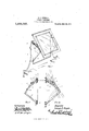
- Figure 1 is a perspective view of a portion of a dressingtable showing my invention applied thereto for the purpose of supporting the adjustable mirror.
- Fig. 2 is a perspective view of one set of levers in the extreme position.
- Fig. 3 is a side elevation of the same also showing in dotted lines another position of the levers, rack-bar and mirror.
- the rack-bar is necessary upon one side only, which may be called the regulating side, and I will confine myself to a description of that side only, the other side being identical (with the exception of the said rack-bar and engagement-pin therefor).
- the plate 6 having pivoted to its upper and lower extremities one end of the upper and lower levers 7 and 8 respectively, the other ends of which are pivoted to the stanchion 9 at points 10 and 11 respectively.
- a rack-bar 12 having on its underside a series of notches 13 is also pivoted to the plate 6 at 1 1, the said. notches being designed and adapted to engage as required with a steady pin 15 for the purpose of retaining the system at any desired angle.
- Patent is 1.
- An improved mirror adjustment consisting of a pair of relatively proportionate levers each pivotally attached at one end to a stanchion and at the other end to a mirror frame, and a rack-bar pivoted between the pivotal attachments of the said levers to the mirror frame and engaging with a pin pro jecting from the upper lever; all substantially as herein set forth and substantially as described and illustrated.
- a pair of relatively proportioned levers each pivotally attached at one end to a stanchion and at the other end to a mirror frame, and a rack-bar pivoted between the pivotal attachments of the said levers to the mirrorframe and engaging With a pin projecting from the upper lever; all in combination 10 with an adjustable mirror of ordinary construction.
Landscapes
- Engineering & Computer Science (AREA)
- Mechanical Engineering (AREA)
- Optical Elements Other Than Lenses (AREA)
Description
G. 0. DUIGAN.
MIRROR ADJUSTMENT.
APPLIOATION FILED MAR. 20. 1911 Patented NOV. 28, 1911.
I Geo/ye d Dayan. vMZ
w/Messes Q ey flu w.
CDLUMBIA PLANOGRA GEORGE OSWALD IDUIGAN. OF MARRIGKVILLE, NEW SOUTH WALES, AUSTRALIA.
MIRROR ADJUSTMENT.
weaver.
Specification of Letters Patent.
Patented Nov. 28, 1911.
Application filed March 20, 1911. Serial No. 615,556.
To all whomz't may concern Be it known that I, Gnonen OswALn DUI- GAN, a subject of the King of Great Britain and Ireland, residing at Averley, Meeks Road, Marrickville, in the State of New South Wales, Commonwealth of Australia, have invented certain new and useful 1mprovements in Mirror Adjustments, of which the following is a specification.
This invention is devised with the object of providing a means for supporting an adjustable mirror which will securely maintain the latter at any desired angle and be capable of easy manipulation.
Various devices have been invented for carrying swinging mirrors, but most of these depend for their efliciency upon frictional contact which under the stress of wear and tear is apt to become loose and consequently useless for the purpose of re taining the mirror at the desired angle.
My invention consists of two sets of levers, one on each side of the mirror, each set consisting of an upper and lower lever, the latter being the longer, each pivoted at one end to the mirror-frame and at the other to the stanchions or uprights which support the mirror. On one of the sets of levers a rackbar pivoted at one end to the mirrorframe, engages with a pin upon the upper lever in such a manner as to retain the mirror at any desired angle within certain limits.
A practical illustration of my invention is shown in the accompanying drawings forming part of this specification and in which Figure 1 is a perspective view of a portion of a dressingtable showing my invention applied thereto for the purpose of supporting the adjustable mirror. Fig. 2 is a perspective view of one set of levers in the extreme position. Fig. 3 is a side elevation of the same also showing in dotted lines another position of the levers, rack-bar and mirror.
As before stated and as will be seen by reference to the drawings, the rack-bar is necessary upon one side only, which may be called the regulating side, and I will confine myself to a description of that side only, the other side being identical (with the exception of the said rack-bar and engagement-pin therefor).
To the side of the mirror frame 5 is aflixed the plate 6 having pivoted to its upper and lower extremities one end of the upper and lower levers 7 and 8 respectively, the other ends of which are pivoted to the stanchion 9 at points 10 and 11 respectively. A rack-bar 12 having on its underside a series of notches 13 is also pivoted to the plate 6 at 1 1, the said. notches being designed and adapted to engage as required with a steady pin 15 for the purpose of retaining the system at any desired angle.
I have found by experiment that the lengths between the pivotal points of the upper lever, the plate 6, the lower lever and the stanchion should be proportionate and that taking the upper lever as the unit these proportions should be approximately as follows Upper lever 1 Plate 6 1.6 Lower lever 2. 6 Stanchion 3.2
Assuming the mirror to be set as shown in Fig. 1 and it being desired to place it in a more vertical position, the lower portion is pushed backward and upward ;the rackbar by the peculiar formation of the notches releases itself from the pin 15 and the notches slide over the pin until the movement ceases when the rack-bar automatically reengages therewith. To restore the mirror to the first position the rack-bar is disengaged and the parts moved until the desired position is attained when the rackbar is againpermitted to engage with the pin and to retain the parts in the new position.
hat I claim and desire to secure by Let ters Patent is 1. An improved mirror adjustment consisting of a pair of relatively proportionate levers each pivotally attached at one end to a stanchion and at the other end to a mirror frame, and a rack-bar pivoted between the pivotal attachments of the said levers to the mirror frame and engaging with a pin pro jecting from the upper lever; all substantially as herein set forth and substantially as described and illustrated.
2. The combination of an upper and lower lever of relative proportionate lengths each pivotally attached at one end to a stanchion and at the other end to a mirror, with a raclebar pivotally attached to the said mirror and engaging a pin upon the upper lever for the purpose of supporting and providing means for adjustment of the said mirror.
3. In devices of the kind set forth, a pair of relatively proportioned levers each pivotally attached at one end to a stanchion and at the other end to a mirror frame, and a rack-bar pivoted between the pivotal attachments of the said levers to the mirrorframe and engaging With a pin projecting from the upper lever; all in combination 10 with an adjustable mirror of ordinary construction.
Signed at Sydney, New South Wales, this 20th day of January, 1911.
GEORGE OSlVALD DUIGANQ WVitnesses:
CHAS. HATTON, WM. NEWTON.
Copies of this patent may be obtained for five cents each, by addressing the Commissioner of Patents, Washington, D. G.
Priority Applications (1)
| Application Number | Priority Date | Filing Date | Title |
|---|---|---|---|
| US61555611A US1009727A (en) | 1911-03-20 | 1911-03-20 | Mirror adjustment. |
Applications Claiming Priority (1)
| Application Number | Priority Date | Filing Date | Title |
|---|---|---|---|
| US61555611A US1009727A (en) | 1911-03-20 | 1911-03-20 | Mirror adjustment. |
Publications (1)
| Publication Number | Publication Date |
|---|---|
| US1009727A true US1009727A (en) | 1911-11-28 |
Family
ID=3078037
Family Applications (1)
| Application Number | Title | Priority Date | Filing Date |
|---|---|---|---|
| US61555611A Expired - Lifetime US1009727A (en) | 1911-03-20 | 1911-03-20 | Mirror adjustment. |
Country Status (1)
| Country | Link |
|---|---|
| US (1) | US1009727A (en) |
Cited By (4)
| Publication number | Priority date | Publication date | Assignee | Title |
|---|---|---|---|---|
| US3074755A (en) * | 1960-02-05 | 1963-01-22 | Renault | Door assembly for a vehicle |
| US4188740A (en) * | 1978-04-06 | 1980-02-19 | Forman Everett W | Mirror-picture |
| US7500655B1 (en) | 2004-08-18 | 2009-03-10 | Smith Frederick L | Adjustable gate bracket apparatus and system |
| US7779568B2 (en) | 2008-03-17 | 2010-08-24 | Adaptive Micro Systems Llc | Adjustable LED sign mounting system |
-
1911
- 1911-03-20 US US61555611A patent/US1009727A/en not_active Expired - Lifetime
Cited By (4)
| Publication number | Priority date | Publication date | Assignee | Title |
|---|---|---|---|---|
| US3074755A (en) * | 1960-02-05 | 1963-01-22 | Renault | Door assembly for a vehicle |
| US4188740A (en) * | 1978-04-06 | 1980-02-19 | Forman Everett W | Mirror-picture |
| US7500655B1 (en) | 2004-08-18 | 2009-03-10 | Smith Frederick L | Adjustable gate bracket apparatus and system |
| US7779568B2 (en) | 2008-03-17 | 2010-08-24 | Adaptive Micro Systems Llc | Adjustable LED sign mounting system |
Similar Documents
| Publication | Publication Date | Title |
|---|---|---|
| US773720A (en) | Adjusting mechanism for couch head-rests, &c. | |
| US1009727A (en) | Mirror adjustment. | |
| US289653A (en) | Assigkoe to h | |
| US380990A (en) | Fastening device | |
| US634352A (en) | Seat. | |
| US777745A (en) | Automatic reclining-chair ratchet. | |
| US449262A (en) | Hand-support for cars | |
| US1173675A (en) | Foot-rest. | |
| US652001A (en) | Lock-hinge. | |
| US480280A (en) | William rochlitz | |
| US839755A (en) | Embalming-table. | |
| US1271676A (en) | Locking device. | |
| US372215A (en) | William f | |
| US344113A (en) | John c | |
| US965430A (en) | Adjustable mirror and support. | |
| US1131487A (en) | Vehicle-seat. | |
| US1069250A (en) | Combined rope-clamp and hook. | |
| US829078A (en) | Adjustable arm for reversible-car-seat backs. | |
| US733857A (en) | Chair. | |
| US176654A (en) | Improvement in | |
| US877646A (en) | Folding and adjustable chair. | |
| US875760A (en) | Reclining-chair. | |
| US985396A (en) | Wrench. | |
| US1007850A (en) | Feeding attachment for disk-sharpeners. | |
| US942485A (en) | Head-rest. |