US10094219B2 - Adiabatic salt energy storage - Google Patents
Adiabatic salt energy storage Download PDFInfo
- Publication number
- US10094219B2 US10094219B2 US12/932,775 US93277511A US10094219B2 US 10094219 B2 US10094219 B2 US 10094219B2 US 93277511 A US93277511 A US 93277511A US 10094219 B2 US10094219 B2 US 10094219B2
- Authority
- US
- United States
- Prior art keywords
- heat storage
- heat
- storage unit
- working fluid
- fluid
- Prior art date
- Legal status (The legal status is an assumption and is not a legal conclusion. Google has not performed a legal analysis and makes no representation as to the accuracy of the status listed.)
- Active, expires
Links
Images


Classifications
-
- F—MECHANICAL ENGINEERING; LIGHTING; HEATING; WEAPONS; BLASTING
- F01—MACHINES OR ENGINES IN GENERAL; ENGINE PLANTS IN GENERAL; STEAM ENGINES
- F01D—NON-POSITIVE DISPLACEMENT MACHINES OR ENGINES, e.g. STEAM TURBINES
- F01D1/00—Non-positive-displacement machines or engines, e.g. steam turbines
- F01D1/02—Non-positive-displacement machines or engines, e.g. steam turbines with stationary working-fluid guiding means and bladed or like rotor, e.g. multi-bladed impulse steam turbines
-
- F—MECHANICAL ENGINEERING; LIGHTING; HEATING; WEAPONS; BLASTING
- F01—MACHINES OR ENGINES IN GENERAL; ENGINE PLANTS IN GENERAL; STEAM ENGINES
- F01K—STEAM ENGINE PLANTS; STEAM ACCUMULATORS; ENGINE PLANTS NOT OTHERWISE PROVIDED FOR; ENGINES USING SPECIAL WORKING FLUIDS OR CYCLES
- F01K5/00—Plants characterised by use of means for storing steam in an alkali to increase steam pressure, e.g. of Honigmann or Koenemann type
-
- F—MECHANICAL ENGINEERING; LIGHTING; HEATING; WEAPONS; BLASTING
- F01—MACHINES OR ENGINES IN GENERAL; ENGINE PLANTS IN GENERAL; STEAM ENGINES
- F01L—CYCLICALLY OPERATING VALVES FOR MACHINES OR ENGINES
- F01L1/00—Valve-gear or valve arrangements, e.g. lift-valve gear
- F01L1/02—Valve drive
-
- F—MECHANICAL ENGINEERING; LIGHTING; HEATING; WEAPONS; BLASTING
- F01—MACHINES OR ENGINES IN GENERAL; ENGINE PLANTS IN GENERAL; STEAM ENGINES
- F01K—STEAM ENGINE PLANTS; STEAM ACCUMULATORS; ENGINE PLANTS NOT OTHERWISE PROVIDED FOR; ENGINES USING SPECIAL WORKING FLUIDS OR CYCLES
- F01K25/00—Plants or engines characterised by use of special working fluids, not otherwise provided for; Plants operating in closed cycles and not otherwise provided for
- F01K25/08—Plants or engines characterised by use of special working fluids, not otherwise provided for; Plants operating in closed cycles and not otherwise provided for using special vapours
- F01K25/10—Plants or engines characterised by use of special working fluids, not otherwise provided for; Plants operating in closed cycles and not otherwise provided for using special vapours the vapours being cold, e.g. ammonia, carbon dioxide, ether
-
- F—MECHANICAL ENGINEERING; LIGHTING; HEATING; WEAPONS; BLASTING
- F01—MACHINES OR ENGINES IN GENERAL; ENGINE PLANTS IN GENERAL; STEAM ENGINES
- F01K—STEAM ENGINE PLANTS; STEAM ACCUMULATORS; ENGINE PLANTS NOT OTHERWISE PROVIDED FOR; ENGINES USING SPECIAL WORKING FLUIDS OR CYCLES
- F01K3/00—Plants characterised by the use of steam or heat accumulators, or intermediate steam heaters, therein
- F01K3/12—Plants characterised by the use of steam or heat accumulators, or intermediate steam heaters, therein having two or more accumulators
-
- F—MECHANICAL ENGINEERING; LIGHTING; HEATING; WEAPONS; BLASTING
- F02—COMBUSTION ENGINES; HOT-GAS OR COMBUSTION-PRODUCT ENGINE PLANTS
- F02C—GAS-TURBINE PLANTS; AIR INTAKES FOR JET-PROPULSION PLANTS; CONTROLLING FUEL SUPPLY IN AIR-BREATHING JET-PROPULSION PLANTS
- F02C1/00—Gas-turbine plants characterised by the use of hot gases or unheated pressurised gases, as the working fluid
- F02C1/04—Gas-turbine plants characterised by the use of hot gases or unheated pressurised gases, as the working fluid the working fluid being heated indirectly
-
- F—MECHANICAL ENGINEERING; LIGHTING; HEATING; WEAPONS; BLASTING
- F02—COMBUSTION ENGINES; HOT-GAS OR COMBUSTION-PRODUCT ENGINE PLANTS
- F02C—GAS-TURBINE PLANTS; AIR INTAKES FOR JET-PROPULSION PLANTS; CONTROLLING FUEL SUPPLY IN AIR-BREATHING JET-PROPULSION PLANTS
- F02C6/00—Plural gas-turbine plants; Combinations of gas-turbine plants with other apparatus; Adaptations of gas-turbine plants for special use
- F02C6/14—Gas-turbine plants having means for storing energy, e.g. for meeting peak loads
-
- F—MECHANICAL ENGINEERING; LIGHTING; HEATING; WEAPONS; BLASTING
- F25—REFRIGERATION OR COOLING; COMBINED HEATING AND REFRIGERATION SYSTEMS; HEAT PUMP SYSTEMS; MANUFACTURE OR STORAGE OF ICE; LIQUEFACTION SOLIDIFICATION OF GASES
- F25B—REFRIGERATION MACHINES, PLANTS OR SYSTEMS; COMBINED HEATING AND REFRIGERATION SYSTEMS; HEAT PUMP SYSTEMS
- F25B11/00—Compression machines, plants or systems, using turbines, e.g. gas turbines
- F25B11/02—Compression machines, plants or systems, using turbines, e.g. gas turbines as expanders
-
- F—MECHANICAL ENGINEERING; LIGHTING; HEATING; WEAPONS; BLASTING
- F25—REFRIGERATION OR COOLING; COMBINED HEATING AND REFRIGERATION SYSTEMS; HEAT PUMP SYSTEMS; MANUFACTURE OR STORAGE OF ICE; LIQUEFACTION SOLIDIFICATION OF GASES
- F25B—REFRIGERATION MACHINES, PLANTS OR SYSTEMS; COMBINED HEATING AND REFRIGERATION SYSTEMS; HEAT PUMP SYSTEMS
- F25B9/00—Compression machines, plants or systems, in which the refrigerant is air or other gas of low boiling point
- F25B9/002—Compression machines, plants or systems, in which the refrigerant is air or other gas of low boiling point characterised by the refrigerant
- F25B9/004—Compression machines, plants or systems, in which the refrigerant is air or other gas of low boiling point characterised by the refrigerant the refrigerant being air
-
- F—MECHANICAL ENGINEERING; LIGHTING; HEATING; WEAPONS; BLASTING
- F25—REFRIGERATION OR COOLING; COMBINED HEATING AND REFRIGERATION SYSTEMS; HEAT PUMP SYSTEMS; MANUFACTURE OR STORAGE OF ICE; LIQUEFACTION SOLIDIFICATION OF GASES
- F25B—REFRIGERATION MACHINES, PLANTS OR SYSTEMS; COMBINED HEATING AND REFRIGERATION SYSTEMS; HEAT PUMP SYSTEMS
- F25B9/00—Compression machines, plants or systems, in which the refrigerant is air or other gas of low boiling point
- F25B9/06—Compression machines, plants or systems, in which the refrigerant is air or other gas of low boiling point using expanders
-
- Y—GENERAL TAGGING OF NEW TECHNOLOGICAL DEVELOPMENTS; GENERAL TAGGING OF CROSS-SECTIONAL TECHNOLOGIES SPANNING OVER SEVERAL SECTIONS OF THE IPC; TECHNICAL SUBJECTS COVERED BY FORMER USPC CROSS-REFERENCE ART COLLECTIONS [XRACs] AND DIGESTS
- Y02—TECHNOLOGIES OR APPLICATIONS FOR MITIGATION OR ADAPTATION AGAINST CLIMATE CHANGE
- Y02E—REDUCTION OF GREENHOUSE GAS [GHG] EMISSIONS, RELATED TO ENERGY GENERATION, TRANSMISSION OR DISTRIBUTION
- Y02E10/00—Energy generation through renewable energy sources
- Y02E10/40—Solar thermal energy, e.g. solar towers
- Y02E10/46—Conversion of thermal power into mechanical power, e.g. Rankine, Stirling or solar thermal engines
-
- Y—GENERAL TAGGING OF NEW TECHNOLOGICAL DEVELOPMENTS; GENERAL TAGGING OF CROSS-SECTIONAL TECHNOLOGIES SPANNING OVER SEVERAL SECTIONS OF THE IPC; TECHNICAL SUBJECTS COVERED BY FORMER USPC CROSS-REFERENCE ART COLLECTIONS [XRACs] AND DIGESTS
- Y02—TECHNOLOGIES OR APPLICATIONS FOR MITIGATION OR ADAPTATION AGAINST CLIMATE CHANGE
- Y02E—REDUCTION OF GREENHOUSE GAS [GHG] EMISSIONS, RELATED TO ENERGY GENERATION, TRANSMISSION OR DISTRIBUTION
- Y02E60/00—Enabling technologies; Technologies with a potential or indirect contribution to GHG emissions mitigation
- Y02E60/14—Thermal energy storage
Definitions
- This invention relates to energy storage.
- Improved energy storage is provided by using a working fluid flowing in a closed cycle including a ganged compressor and turbine, and capable of efficient heat exchange with heat storage fluids on a hot side of the system and on a cold side of the system.
- This system can operate as a heat engine by transferring heat from the hot side to the cold side to mechanically drive the turbine.
- the system can also operate as a refrigerator by mechanically driving the compressor to transfer heat from the cold side to the hot side.
- Heat exchange between the working fluid of the system and the heat storage fluids occurs in counter-flow heat exchangers.
- the hot side and cold side heat storage fluids each have a corresponding pair of storage tanks, where heat transfer to/from a heat storage fluid entails flow of the heat storage liquid between its two corresponding storage tanks.
- molten salt is the hot-side heat storage fluid and water is the cold-side heat storage fluid.
- a steam explosion from such a facility could have an explosive force on the order of thousands of tons of TNT.
- Using a closed loop for the working fluid advantageously increases cold-side heat transfer rates, allows a broader selection of working fluids, allows for operation at elevated cold-side pressure, improves efficiency, and reduces the risk of turbine damage.
- FIG. 1 shows an exemplary embodiment of the invention.
- FIG. 2 shows operation of the example of FIG. 1 in a heat engine mode that uses heat energy to provide mechanical work.
- FIG. 3 shows operation of the example of FIG. 1 in a refrigerator mode that uses mechanical work to store heat energy.
- FIG. 4 shows an idealized thermodynamic Brayton cycle that relates to operation of embodiments of the invention.
- FIG. 5 show plots of compressor efficiency vs. number of compressor stages.
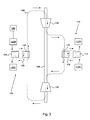
- FIG. 1 shows an exemplary embodiment of the invention.
- a working fluid (schematically referenced as 108 ) flows in a closed cycle that includes, in sequence, a compressor 102 , a first heat storage unit 110 , a turbine 104 , and a second heat storage unit 120 .
- Compressor 102 and turbine 104 are ganged on a common mechanical shaft 106 such that they rotate together.
- Heat storage units 110 and 120 are both capable of exchanging heat with working fluid 108 .
- pipes for defining the flow paths of fluids (e.g., working fluid 108 ) are not shown on FIGS. 1-3 . Suitable pipes for the working fluid and heat storage fluids described herein are known in the art.
- this apparatus is capable of operating as a heat engine (to provide mechanical work from heat) or as a refrigerator (to use mechanical work to store heat).
- heat storage units 110 and 120 The purpose of heat storage units 110 and 120 is to provide stored heat to working fluid 108 and to remove heat from working fluid 108 for storage. It can be helpful to refer to first heat storage unit 110 as the hot-side heat storage unit, and to refer to second heat storage unit 120 as the cold-side heat storage unit. This terminology can be understood by noting that hot-side heat storage unit 110 adds heat to working fluid 108 at the same point in the cycle that combustion of fuel adds heat to air in a conventional jet engine. Thus, it can be helpful to regard hot-side heat storage unit 110 as being analogous to the fuel in a jet engine, when the apparatus is operating as a heat engine.
- Heat storage units 110 and 120 preferably have several features to improve efficiency, as shown on FIGS. 1-3 .
- First heat storage unit 110 preferably includes a first hot heat storage tank 112 H, a first cold heat storage tank 112 C, a first heat storage fluid 118 capable of flowing between tanks 112 H and 112 C to store or release heat, and a first counter-flow heat exchanger 116 .
- counter-flow heat exchanger 116 it is important that working fluid 108 and first heat storage fluid 118 flow in opposite directions, as shown.
- First heat storage unit 110 also includes a valve 114 that can switch connections between heat exchanger 116 and tanks 112 H, 112 C as needed for the heat engine and refrigerator modes.
- Second heat storage unit 120 preferably includes a second hot heat storage tank 122 H, a second cold heat storage tank 122 C, a second heat storage fluid 128 capable of flowing between tanks 122 H and 122 C to store or release heat, and a second counter-flow heat exchanger 126 .
- Second heat storage unit 120 also includes a valve 124 that can switch connections between heat exchanger 126 and tanks 122 H, 122 C as needed for the heat engine and refrigerator modes.
- Counter-flow heat exchangers 116 and 126 can be designed according to known principles to reduce entropy generation in the heat exchangers to negligible levels compared to the compressor entropy generation.
- the basic idea is to have very small temperature differences between any two fluid elements that are exchanging heat, thereby reducing entropy production (and eliminating it entirely in the idealized case).
- the heat storage tanks are thermally insulated tanks that can hold a suitable quantity of the relevant heat storage fluid.
- the heat storage fluids are the medium of heat storage. Liquids are preferred over solids or gases because of the need for extremely rapid exchange of large amounts of heat by convective counterflow. They also allow for relatively compact storage of large amounts of energy.
- the size of each storage unit i.e. 110 and 120 on FIG. 1
- Each heat exchanger i.e. 116 and 126 on FIG. 1
- the heat storage fluid i.e., fluid 118
- the heat storage fluid be a molten salt or mixture of molten salts.
- a preferred molten salt is a eutectic (i.e. lowest melting point) mixture of sodium nitrate and potassium nitrate.
- any salt or salt mixture that is liquid over the operating temperature range can be employed.
- Such molten salts can provide numerous advantages, including low vapor pressure (which is important for safety), melting point below the creep temperature of steels, low corrosiveness, low capacity to dissolve iron and nickel, chemical stability, lack of toxicity, and low cost.
- the heat storage fluid i.e., fluid 128
- the heat storage fluid be liquid water. It is important to ensure that no steam is present on the cold side, because the presence of steam creates a significant explosion hazard.
- 100° C. is an upper limit for the temperature of heat storage fluid 128 if water is used.
- efficiency is improved by increasing the temperature difference at which the system operates.
- a mixture of water and one or more antifreeze compounds e.g., ethylene glycol, propylene glycol and glycerol
- 100° C. e.g., ⁇ 30° C. to 100° C.
- FIG. 1 also preferably includes a radiator 130 for dissipating waste heat generated by operation of the apparatus.
- the radiator is coupled to the second hot heat storage tank 122 H, as shown.
- practice of the invention does not depend critically on the location of the radiator, because waste heat can also be removed at other points in the cycle.
- FIG. 4 A idealized thermodynamic Brayton cycle is shown on FIG. 4 as a pressure-volume diagram.
- FIG. 2 shows operation of the example of FIG. 1 in a heat engine mode that uses heat energy to provide mechanical work.
- the hot-side storage tanks 112 H and 112 C have substantially different fluid temperatures (e.g., as would result from prior operation of the apparatus to store energy).
- Working fluid 108 at the input of compressor 102 is represented by point 408 on FIG. 4 . Compression of working fluid 108 moves the system to point 402 on FIG. 4 .
- Heat is added by heat storage unit 110 to move the system from 402 to 404 on FIG. 4 .
- valve 114 provides connections as shown such that heat storage fluid flows from tank 112 H to tank 112 C through heat exchanger 116 , thereby providing heat to working fluid 108 .
- Working fluid 108 expands in turbine 104 to move the system from 404 to 406 on FIG. 4 .
- Mechanical energy is provided by the apparatus in this mode, because the work released by expanding from 404 to 406 on FIG. 4 is greater than the work required to compress from 408 to 402 on FIG. 4 .
- thermodynamic cycle of FIG. 4 is closed by connecting the exhaust of turbine 104 to the input of compressor 102 through the cold-side heat storage unit 120 .
- Heat is removed from working fluid 108 by heat storage unit 120 to move the system from 406 to 408 on FIG. 4 .
- valve 124 provides connections as shown such that heat storage fluid flows from tank 122 C to tank 122 H through heat exchanger 126 , thereby storing heat provided by working fluid 108 .
- This step can be understood as storing the heat energy present in the (hot) exhaust from turbine 104 .
- Hot-side heat storage unit 110 and cold-side heat storage unit 120 have comparable total heat capacity. The need for this can be appreciated in connection with the generation mode of FIG. 2 , where it is apparent that cold-side heat storage unit 120 stores a fraction of the heat stored in hot-side heat storage unit 110 (i.e., the fraction of the stored hot-side heat that ends up in the exhaust from turbine 104 ).
- FIG. 3 shows operation of the example of FIG. 1 in a refrigerator mode that uses mechanical work to store heat energy.
- Working fluid 108 at the input of compressor 102 is represented by point 406 on FIG. 4 . Compression of working fluid 108 moves the system to point 404 on FIG. 4 . Heat is removed by heat storage unit 110 to move the system from 404 to 402 on FIG. 4 . More specifically, valve 114 provides connections as shown such that heat storage fluid flows from tank 112 C to tank 112 H through heat exchanger 116 , thereby removing heat from working fluid 108 .
- Working fluid 108 expands in turbine 104 to move the system from 402 to 404 on FIG. 4 . Mechanical energy must be provided to the apparatus in this mode, because the work released by expanding from 402 to 408 on FIG. 4 is less than the work required to compress from 406 to 404 on FIG. 4 .
- thermodynamic cycle of FIG. 4 is closed by connecting the exhaust of turbine 104 to the input of compressor 102 through the cold-side heat storage unit 120 .
- Heat is added to working fluid 108 by heat storage unit 120 to move the system from 408 to 406 on FIG. 4 .
- valve 124 provides connections as shown such that heat storage fluid flows from tank 122 H to tank 122 C through heat exchanger 126 , thereby providing heat to working fluid 108 .
- This step can be understood as warming up the (cold) exhaust from turbine 104 .
- two of the storage tanks 112 H, 112 C, 122 H, and 112 C will be feeding heat storage fluid to the system, and the other two tanks will be receiving heat storage fluid.
- the feed tanks set their own temperatures.
- the receiving tanks see fluid temperatures that depend on how the system is operating—i.e., its loads and/or power input. Ideally, the receiving tank fluid temperatures are set by the Brayton cycle conditions, but in practice there will be deviations from these conditions, and the pressure ratio varies in response to system demand.
- a system controller (not shown) controls system parameters in order to approximately match the ideal temperature conditions.
- Suitable system parameters include but are not limited to: the flow rate of first heat storage fluid 118 , the flow rate of second heat storage fluid 128 , and operating parameters of compressor 102 and turbine 104 such as turbine stator blade positions. Because of entropy creation within the system, it will not be possible to match the ideal temperature conditions exactly, and at least one of the four tank temperatures will be too high.
- the purpose of radiator 130 is to reject this waste heat to the environment as part of system control. Suitable techniques for controlling systems as described herein are known in the art.
- hot-side heat storage fluid 118 is a molten salt and cold-side heat storage fluid 128 is water.
- cold-side heat storage fluid 128 is water.
- there is a water side and a salt side each characterized by two temperatures.
- these 4 temperatures are not independent of each other.
- Each salt temperature is the product of the corresponding water temperature and a factor that depends on the compressor pressure ratio (numerically, this factor is typically about 2).
- the water temperatures need to be in the liquid range for water (at 1 atmosphere) for safety, and the salt temperatures need to be in the liquid range for the relevant salt, and be at a temperature range that structural steels can handle.
- salts that are molten at temperatures on the order of 450-700 K are known, and such temperatures are well below typical steel melting or creep temperatures.
- the cold-side heat storage unit 120 could be removed from FIG. 1 , thereby opening the cycle such that the compressor input is provided by the environment, and the turbine exhausts to the environment.
- the open-cycle approach has numerous and severe disadvantages.
- the open-cycle approach entails employing atmospheric air as the cold-side heat reservoir. This automatically precludes the use of any working fluid other than air. It also precludes the use of counterflow heat exchange to minimize entropy production. It also exposes the system to environmental dangers, for example humidity fluctuations that could cause condensation or even freezing of water in the turbine operating in refrigerator mode, with total destruction of the turbine as the likely result.
- a particularly important modification of the working fluid allowed by a closed cycle is pressurization. This enables the input pressure to compressor 102 to be higher than atmospheric pressure. It is helpful to consider the minimum pressure (P min ) of working fluid 108 in its closed cycle. The minimum pressure is typically found on the cold side of the apparatus (e.g., at the input to compressor 102 ). Although P min can be as low as 1 atmosphere (atm), it is preferred for P min to be about 10 atmospheres or greater.
- a storage turbine at 1 atm pressure generates about 1/10 the power of a combustion turbine of the same size. This can be seen by comparing the exhaust temperatures.
- a large commercial power gas turbine has an output of 256 megawatts, a compression ratio of 15.3 and an exhaust temperature of 608° C. (i.e. 578° C. greater than the intake temperature).
- the throat intake speed of industrial gas turbines is typically a significant fraction of the sound speed in air (e.g., Mach 0.5). Since sea level air has a mass density of 1.22 kg/m 3 and a sound speed of 343 m/s, the throat area required to accommodate the mass flow is about 3 m 2 . The power required merely to accelerate the air mass in question to Mach 0.5 is about 9.5 MW. Some of this power can be recovered from exhaust hydrodynamics, but not all, and the lost part is comparable to the energy one is trying to extract.
- the power output of the turbine of a given size be substantially raised. This can be done by raising the ambient pressure of the working fluid. If, for example, the pressure is raised to 10 atmospheres, something that steel can accommodate easily, the power output becomes 10 times what it was before, which is an amount comparable to that generated by a combustion gas turbine of the same size.
- the pressures and temperatures in question also feature in modern supercritical steam plants, so the steel is expected to be able to take the stress.
- the elevated working fluid density should also help raise the compressor efficiency, although the exact amount is difficult to estimate accurately. Water (i.e., a dense fluid) can be pumped uphill with 90% efficiency using Francis turbines. This high efficiency is what makes hydropumping the leading energy storage technology at the moment.
- the closed loop also enables one to conserve momentum, as in a wind tunnel. This becomes increasingly important as the mass of the fluid rises, for then the total fluid kinetic energy passing by a point per second can become comparable to the power one is trying to store or extract. In a closed circuit this energy is automatically conserved (except for friction losses at the walls) so it doesn't reduce efficiency but in an open circuit, where kinetic energy gets lost to the environment, it does reduce efficiency.
- T 1 T 0 ⁇ ( P 1 / P 0 ) ⁇ - 1 ⁇ , ( 1 )
- ⁇ is the heat capacity ratio (i.e., C p /C v ) of the gas.
- E store ⁇ ⁇ - 1 ⁇ R ⁇ ⁇ ⁇ ⁇ T ⁇ [ 1 - ( P 0 / P 1 ) ⁇ - 1 ⁇ ] , ( 3 )
- ⁇ T is the temperature difference between the hot and cold storage tanks (e.g., 112 H and 112 C).
- the thermodynamic efficiency of energy storage ( ⁇ store ) is given by
- the efficiency of retrieval is the same as for storage, so the total efficiency for storage+retrieval is ⁇ store 2 .
- a preferred working fluid is Argon.
- Argon is inexpensive, and has better properties than air. More specifically, ⁇ for Argon is 1.66 and ⁇ for air is 1.4, so Argon is seen to improve the efficiency given by Eqn. 4.
- the compressor is the dominant source of inefficiency in the present apparatus.
- Axial compressors (e.g. those in jets and as shown on FIGS. 1-3 ) tend to be the most efficient kind of compressor, particularly in applications requiring large volume flows.
- the overall compressor efficiency degrades with stage number n according to:
- ⁇ c r n ⁇ ( ⁇ - 1 ) / ⁇ - 1 r n ⁇ ( ⁇ - 1 ) / ⁇ s ⁇ ⁇ - 1 ⁇ ⁇
- ⁇ ⁇ r [ P 1 P 0 ] 1 / n . ( 5 )
- the retrieval-step efficiency is the same, so the round-trip storage efficiency is the square of this number, or 0.64.
Landscapes
- Engineering & Computer Science (AREA)
- Mechanical Engineering (AREA)
- General Engineering & Computer Science (AREA)
- Chemical & Material Sciences (AREA)
- Combustion & Propulsion (AREA)
- Engine Equipment That Uses Special Cycles (AREA)
Abstract
Description
where γ is the heat capacity ratio (i.e., Cp/Cv) of the gas. The heat dumped to the environment per mole of working fluid compressed (Qdump) is given by
where R is the ideal gas constant, ηc is the compressor efficiency, and Te is the environment temperature. It is assumed that the compressor is the dominant source of entropy production in the cycle. This assumption is reasonable in view of the use of counter-flow heat exchangers and the high efficiencies provided by turbines in practice. The energy stored per mole of working fluid compressed (Estore) is given by
where ΔT is the temperature difference between the hot and cold storage tanks (e.g., 112H and 112C). The thermodynamic efficiency of energy storage (ηstore) is given by
For a numerical example, let P1/P0=14, ηc=0.9, Te=300 K, ΔT=150 K and γ=1.4. The resulting storage efficiency is ηstore=0.857. The efficiency of retrieval is the same as for storage, so the total efficiency for storage+retrieval is ηstore 2.
ΔT H=(P 1 /P 0)(γ−1)/γ ΔT C. (6)
For P1/P0=14, γ=1.4 (i.e., air), and ΔTC=75 K, the resulting ΔTH is about 150K (more specifically, it is 159 K). The value for ΔTC in this example is a conservative liquid range for water. It is highly undesirable to pressurize the water to allow temperatures greater than 100° C., on account of the extreme explosion danger thereby created. Thus the only practical way to increase this range is extend the cold side to below room temperature. One can obtain a further 25 K by going down to the freezing point of water and a further 30 K if antifreeze is added as described above. Assuming ΔTC=130 K, the hot-side temperature difference then becomes ΔTH=276 K which gives a corresponding storage efficiency of ηstore=0.91.
Claims (20)
Priority Applications (5)
| Application Number | Priority Date | Filing Date | Title |
|---|---|---|---|
| US12/932,775 US10094219B2 (en) | 2010-03-04 | 2011-03-04 | Adiabatic salt energy storage |
| US13/965,048 US9932830B2 (en) | 2010-03-04 | 2013-08-12 | Adiabatic salt electric energy storage |
| US16/111,151 US10907513B2 (en) | 2010-03-04 | 2018-08-23 | Adiabatic salt energy storage |
| US17/164,302 US11761336B2 (en) | 2010-03-04 | 2021-02-01 | Adiabatic salt energy storage |
| US18/237,606 US20230399948A1 (en) | 2010-03-04 | 2023-08-24 | Adiabatic salt energy storage |
Applications Claiming Priority (2)
| Application Number | Priority Date | Filing Date | Title |
|---|---|---|---|
| US33957710P | 2010-03-04 | 2010-03-04 | |
| US12/932,775 US10094219B2 (en) | 2010-03-04 | 2011-03-04 | Adiabatic salt energy storage |
Related Child Applications (2)
| Application Number | Title | Priority Date | Filing Date |
|---|---|---|---|
| US13/965,048 Continuation US9932830B2 (en) | 2010-03-04 | 2013-08-12 | Adiabatic salt electric energy storage |
| US16/111,151 Continuation US10907513B2 (en) | 2010-03-04 | 2018-08-23 | Adiabatic salt energy storage |
Publications (2)
| Publication Number | Publication Date |
|---|---|
| US20160298455A1 US20160298455A1 (en) | 2016-10-13 |
| US10094219B2 true US10094219B2 (en) | 2018-10-09 |
Family
ID=57111282
Family Applications (5)
| Application Number | Title | Priority Date | Filing Date |
|---|---|---|---|
| US12/932,775 Active 2031-05-10 US10094219B2 (en) | 2010-03-04 | 2011-03-04 | Adiabatic salt energy storage |
| US13/965,048 Active 2032-06-21 US9932830B2 (en) | 2010-03-04 | 2013-08-12 | Adiabatic salt electric energy storage |
| US16/111,151 Active 2031-03-06 US10907513B2 (en) | 2010-03-04 | 2018-08-23 | Adiabatic salt energy storage |
| US17/164,302 Active US11761336B2 (en) | 2010-03-04 | 2021-02-01 | Adiabatic salt energy storage |
| US18/237,606 Abandoned US20230399948A1 (en) | 2010-03-04 | 2023-08-24 | Adiabatic salt energy storage |
Family Applications After (4)
| Application Number | Title | Priority Date | Filing Date |
|---|---|---|---|
| US13/965,048 Active 2032-06-21 US9932830B2 (en) | 2010-03-04 | 2013-08-12 | Adiabatic salt electric energy storage |
| US16/111,151 Active 2031-03-06 US10907513B2 (en) | 2010-03-04 | 2018-08-23 | Adiabatic salt energy storage |
| US17/164,302 Active US11761336B2 (en) | 2010-03-04 | 2021-02-01 | Adiabatic salt energy storage |
| US18/237,606 Abandoned US20230399948A1 (en) | 2010-03-04 | 2023-08-24 | Adiabatic salt energy storage |
Country Status (1)
| Country | Link |
|---|---|
| US (5) | US10094219B2 (en) |
Cited By (22)
| Publication number | Priority date | Publication date | Assignee | Title |
|---|---|---|---|---|
| US10794277B2 (en) | 2017-11-21 | 2020-10-06 | Aestus Energy Storage, LLC | Thermal storage system charging |
| US10830134B2 (en) | 2016-12-31 | 2020-11-10 | Malta Inc. | Modular thermal storage |
| US10895409B2 (en) | 2017-11-21 | 2021-01-19 | Aestus Energy Storage, LLC | Thermal storage system charging |
| US10920674B2 (en) | 2016-12-28 | 2021-02-16 | Malta Inc. | Variable pressure inventory control of closed cycle system with a high pressure tank and an intermediate pressure tank |
| US11286804B2 (en) | 2020-08-12 | 2022-03-29 | Malta Inc. | Pumped heat energy storage system with charge cycle thermal integration |
| US11352951B2 (en) | 2016-12-30 | 2022-06-07 | Malta Inc. | Variable pressure turbine |
| US11396826B2 (en) | 2020-08-12 | 2022-07-26 | Malta Inc. | Pumped heat energy storage system with electric heating integration |
| US11428445B2 (en) | 2019-09-05 | 2022-08-30 | Gridworthy Technologies LLC | System and method of pumped heat energy storage |
| US11454168B2 (en) | 2016-12-28 | 2022-09-27 | Malta Inc. | Pump control of closed cycle power generation system |
| US11454167B1 (en) | 2020-08-12 | 2022-09-27 | Malta Inc. | Pumped heat energy storage system with hot-side thermal integration |
| US11480067B2 (en) | 2020-08-12 | 2022-10-25 | Malta Inc. | Pumped heat energy storage system with generation cycle thermal integration |
| US11486305B2 (en) | 2020-08-12 | 2022-11-01 | Malta Inc. | Pumped heat energy storage system with load following |
| US11512613B2 (en) | 2016-12-28 | 2022-11-29 | Malta Inc. | Storage of excess heat in cold side of heat engine |
| US11578622B2 (en) | 2016-12-29 | 2023-02-14 | Malta Inc. | Use of external air for closed cycle inventory control |
| US11591956B2 (en) | 2016-12-28 | 2023-02-28 | Malta Inc. | Baffled thermoclines in thermodynamic generation cycle systems |
| US11678615B2 (en) | 2018-01-11 | 2023-06-20 | Lancium Llc | Method and system for dynamic power delivery to a flexible growcenter using unutilized energy sources |
| US11754319B2 (en) | 2012-09-27 | 2023-09-12 | Malta Inc. | Pumped thermal storage cycles with turbomachine speed control |
| US11761336B2 (en) | 2010-03-04 | 2023-09-19 | Malta Inc. | Adiabatic salt energy storage |
| US11852043B2 (en) | 2019-11-16 | 2023-12-26 | Malta Inc. | Pumped heat electric storage system with recirculation |
| US11982228B2 (en) | 2020-08-12 | 2024-05-14 | Malta Inc. | Pumped heat energy storage system with steam cycle |
| US12123327B2 (en) | 2020-08-12 | 2024-10-22 | Malta Inc. | Pumped heat energy storage system with modular turbomachinery |
| US12428979B2 (en) | 2021-12-14 | 2025-09-30 | Malta Inc. | Pumped heat energy storage system integrated with coal-fired energy generation unit |
Families Citing this family (33)
| Publication number | Priority date | Publication date | Assignee | Title |
|---|---|---|---|---|
| EP2594753A1 (en) * | 2011-11-21 | 2013-05-22 | Siemens Aktiengesellschaft | Thermal energy storage and recovery system comprising a storage arrangement and a charging/discharging arrangement being connected via a heat exchanger |
| US10082045B2 (en) | 2016-12-28 | 2018-09-25 | X Development Llc | Use of regenerator in thermodynamic cycle system |
| US10280804B2 (en) | 2016-12-29 | 2019-05-07 | Malta Inc. | Thermocline arrays |
| US10082104B2 (en) | 2016-12-30 | 2018-09-25 | X Development Llc | Atmospheric storage and transfer of thermal energy |
| CN107131556B (en) * | 2017-02-07 | 2019-07-05 | 陈春材 | Air conditioner |
| CN108052773B (en) * | 2017-12-29 | 2019-02-12 | 河海大学 | Calculation method of air volume and air pressure in the vertical shaft structure |
| JP7159346B2 (en) * | 2018-04-18 | 2022-10-24 | カーボン-クリーン テクノロジーズ ゲゼルシャフト ミット ベシュレンクテル ハフツング | Method of operating regenerative heat storage device and heat storage device |
| GB201808478D0 (en) * | 2018-05-23 | 2018-07-11 | Univ Edinburgh | Ultra-high temperature thermal energy storage system |
| JP7065745B2 (en) * | 2018-10-12 | 2022-05-12 | 大陽日酸株式会社 | Ultra-low temperature fluid circulation cooling system |
| IT201900002385A1 (en) | 2019-02-19 | 2020-08-19 | Energy Dome S P A | Plant and process for the accumulation of energy |
| US12291982B2 (en) | 2020-11-30 | 2025-05-06 | Rondo Energy, Inc. | Thermal energy storage systems for use in material processing |
| CN110185503B (en) * | 2019-06-14 | 2024-08-09 | 国家电投集团科学技术研究院有限公司 | Energy storage power generation circulation system |
| CN110159380B (en) * | 2019-06-14 | 2024-06-07 | 国家电投集团科学技术研究院有限公司 | Single-tank closed-type circulating energy storage power generation system |
| DE102019127431B4 (en) | 2019-10-11 | 2021-05-06 | Enolcon Gmbh | Thermal power storage with fixed bed heat storage and fixed bed cold storage and method for operating a thermal power storage |
| IT202000003680A1 (en) | 2020-02-21 | 2021-08-21 | Energy Dome S P A | Plant and process for the accumulation of energy |
| US11162387B1 (en) * | 2020-07-14 | 2021-11-02 | Photon Vault, Llc | Multi-temperature heat pump for thermal energy storage |
| US11519655B2 (en) | 2020-07-31 | 2022-12-06 | Photon Vault, Llc | Thermal energy storage and retrieval systems and methods |
| US11428476B2 (en) | 2020-09-04 | 2022-08-30 | Photon Vault, Llc | Thermal energy storage and retrieval system |
| US12449210B2 (en) | 2020-09-04 | 2025-10-21 | Photon Vault, Llc | Thermal energy system with bonded aggregate blocks comprising graphite |
| EP4217593B1 (en) | 2020-09-25 | 2024-10-30 | Energy Dome S.p.A. | Plant and process for energy storage |
| US12276442B2 (en) | 2020-11-09 | 2025-04-15 | Photon Vault, Llc | Multi-temperature heat collection system |
| EP4150282B1 (en) | 2020-11-30 | 2025-01-01 | Rondo Energy, Inc. | Energy storage system and applications |
| US12146424B2 (en) | 2020-11-30 | 2024-11-19 | Rondo Energy, Inc. | Thermal energy storage system coupled with a solid oxide electrolysis system |
| US12018596B2 (en) | 2020-11-30 | 2024-06-25 | Rondo Energy, Inc. | Thermal energy storage system coupled with thermal power cycle systems |
| US11913362B2 (en) | 2020-11-30 | 2024-02-27 | Rondo Energy, Inc. | Thermal energy storage system coupled with steam cracking system |
| US12359591B1 (en) | 2020-11-30 | 2025-07-15 | Rondo Energy, Inc. | Thermal energy storage systems for repowering existing power plants for improving efficiency and safety |
| US11913361B2 (en) | 2020-11-30 | 2024-02-27 | Rondo Energy, Inc. | Energy storage system and alumina calcination applications |
| US11815016B2 (en) * | 2021-03-19 | 2023-11-14 | 247Solar Inc. | Thermal storage and power generation systems and methods for electrical power source management |
| DK181096B1 (en) | 2021-04-14 | 2022-12-12 | Stiesdal Storage As | Thermal energy storage system with a spray of phase change material and method of its operation |
| CN113339091B (en) * | 2021-07-16 | 2023-03-10 | 中国科学院上海应用物理研究所 | Brayton-Karina cycle energy storage power supply method and device |
| CN114417229B (en) * | 2022-01-25 | 2023-02-28 | 西安交通大学 | Two-dimensional calculation method for nuclear reactor steam explosion |
| IES87598Y1 (en) | 2023-04-14 | 2025-04-09 | Rondo Energy Inc | Thermal energy storage blocks and associated support structures |
| US12480719B2 (en) | 2024-04-24 | 2025-11-25 | Rondo Energy, Inc. | Thermal energy storage system for simple and combined cycle power generation |
Citations (138)
| Publication number | Priority date | Publication date | Assignee | Title |
|---|---|---|---|---|
| US2065974A (en) | 1933-12-23 | 1936-12-29 | Marguerre Fritz | Thermodynamic energy storage |
| US2246513A (en) | 1939-10-28 | 1941-06-24 | Charles A Hammond | Mold for making cellular cores for radiators |
| US2791204A (en) | 1951-08-16 | 1957-05-07 | Smith Corp A O | Water heater utilizing heat of crystallization |
| US2860493A (en) | 1951-06-04 | 1958-11-18 | Capps Martin William Richard | Heat-pump apparatus for providing heat for domestic and like purposes |
| US3152442A (en) | 1962-05-04 | 1964-10-13 | Richard J Rowekamp | System for converting solar energy into useful energy |
| US3220191A (en) * | 1961-05-25 | 1965-11-30 | Escher Wyss Ag | Varying the pressure level of a closed-cycle gas turbine plant |
| US3630022A (en) | 1968-09-14 | 1971-12-28 | Rolls Royce | Gas turbine engine power plants |
| US3897170A (en) | 1974-01-09 | 1975-07-29 | Arthur Darvishian | Wind motor |
| US3955359A (en) | 1973-06-20 | 1976-05-11 | Westinghouse Electric Corporation | Bearing temperature system failure detection apparatus suitable for use in power plants and like apparatus |
| US4024908A (en) * | 1976-01-29 | 1977-05-24 | Milton Meckler | Solar powered heat reclamation air conditioning system |
| US4054124A (en) * | 1976-04-06 | 1977-10-18 | Knoeoes Stellan | Solar radiation collection system |
| US4089744A (en) * | 1976-11-03 | 1978-05-16 | Exxon Research & Engineering Co. | Thermal energy storage by means of reversible heat pumping |
| US4094148A (en) | 1977-03-14 | 1978-06-13 | Stone & Webster Engineering Corporation | Thermal storage with molten salt for peaking power |
| US4110987A (en) * | 1977-03-02 | 1978-09-05 | Exxon Research & Engineering Co. | Thermal energy storage by means of reversible heat pumping utilizing industrial waste heat |
| US4148191A (en) | 1975-12-23 | 1979-04-10 | Bbc Brown, Boveri & Company Limited | Method for regulating the power output of a thermodynamic system operating on a closed gas cycle and apparatus for carrying out the method |
| US4158384A (en) * | 1977-08-18 | 1979-06-19 | Brautigam Robert F | Heat storage system |
| EP0003980A1 (en) | 1978-03-13 | 1979-09-19 | Messerschmitt-Bölkow-Blohm Gesellschaft mit beschränkter Haftung | Thermal energy storage device |
| US4215553A (en) | 1978-06-26 | 1980-08-05 | Sanders Associates, Inc. | Energy conversion system |
| US4408654A (en) | 1979-07-05 | 1983-10-11 | Doomernik B.V. | Accumulator for storing heat or cold |
| US4430241A (en) | 1982-07-01 | 1984-02-07 | Olin Corporation | Mixed nitrate salt heat transfer medium and process for providing the same |
| US4438630A (en) | 1982-09-07 | 1984-03-27 | Combustion Engineering, Inc. | Method and system for maintaining operating temperatures in a molten salt co-generating unit |
| US4444024A (en) | 1981-08-04 | 1984-04-24 | Mcfee Richard | Dual open cycle heat pump and engine |
| US4479352A (en) * | 1981-07-21 | 1984-10-30 | Mitsui Engineering & Shipbuilding Co., Ltd. | Hot-water storage type power generating unit |
| US4523629A (en) | 1982-09-30 | 1985-06-18 | The United States Of America As Represented By The United States Department Of Energy | Method and apparatus for operating an improved thermocline storage unit |
| US4583372A (en) | 1985-01-30 | 1986-04-22 | At&T Technologies, Inc. | Methods of and apparatus for storing and delivering a fluid |
| US4628692A (en) | 1980-09-04 | 1986-12-16 | Pierce John E | Solar energy power system |
| US4643212A (en) | 1984-03-28 | 1987-02-17 | Chicago Bridge & Iron Company | Hot liquid thermal energy storage tank and method |
| US4727930A (en) * | 1981-08-17 | 1988-03-01 | The Board Of Regents Of The University Of Washington | Heat transfer and storage system |
| US5269145A (en) | 1991-06-28 | 1993-12-14 | Deutsche Forschungsanstalt Fuer Luft- Und Raumfahrt E.V. | Heat storage system with combined heat storage device |
| JPH0893633A (en) | 1994-09-20 | 1996-04-09 | Saga Univ | Energy converter |
| US5537822A (en) * | 1994-02-03 | 1996-07-23 | The Israel Electric Corporation Ltd. | Compressed air energy storage method and system |
| US5644928A (en) | 1992-10-30 | 1997-07-08 | Kajima Corporation | Air refrigerant ice forming equipment |
| US5653656A (en) | 1992-03-02 | 1997-08-05 | Dayco Products, Inc. | Toothed belt formed mainly of thermoplastic material |
| US5653670A (en) | 1992-09-04 | 1997-08-05 | Endelman; Ken | Exercise apparatus |
| US6119682A (en) * | 1996-07-30 | 2000-09-19 | Hazan; Haim | Water heater and storage tank |
| US20010054449A1 (en) | 1998-08-20 | 2001-12-27 | Doncasters Plc | Alloy pipes and methods of making same |
| US20030131623A1 (en) | 2001-09-05 | 2003-07-17 | Suppes Galen J. | Heat pump using phase change materials |
| US6629413B1 (en) | 1999-04-28 | 2003-10-07 | The Commonwealth Of Australia Commonwealth Scientific And Industrial Research Organization | Thermodynamic apparatus |
| US6644062B1 (en) | 2002-10-15 | 2003-11-11 | Energent Corporation | Transcritical turbine and method of operation |
| US20040008010A1 (en) | 2002-06-18 | 2004-01-15 | Mohammed Ebrahim | Microturbine engine system |
| US6701711B1 (en) | 2002-11-11 | 2004-03-09 | The Boeing Company | Molten salt receiver cooling system |
| US20040083731A1 (en) | 2002-11-01 | 2004-05-06 | George Lasker | Uncoupled, thermal-compressor, gas-turbine engine |
| US20040088980A1 (en) | 2000-08-11 | 2004-05-13 | Andreas Emmel | Method for converting thermal energy into mechanical work |
| KR20040045337A (en) | 2002-11-22 | 2004-06-01 | 게아 루프트퀄러 게엠베하 | Heat exchanger, and method of making a heat exchanger |
| WO2005019756A2 (en) | 2003-08-11 | 2005-03-03 | Graham Robert G | Monolithic tube sheet and method of manufacture |
| US20050126171A1 (en) | 2002-11-01 | 2005-06-16 | George Lasker | Uncoupled, thermal-compressor, gas-turbine engine |
| EP1577548A1 (en) | 2004-03-16 | 2005-09-21 | Abb Research Ltd. | Apparatus and method for storing thermal energy and generating electricity |
| US20060035591A1 (en) | 2004-06-14 | 2006-02-16 | Weatherford/Lamb, Inc. | Methods and apparatus for reducing electromagnetic signal noise |
| US20060053792A1 (en) * | 2004-09-13 | 2006-03-16 | Bourgeois Richard S | Power generation system and method of operating same |
| US7028481B1 (en) | 2003-10-14 | 2006-04-18 | Sandia Corporation | High efficiency Brayton cycles using LNG |
| US20060137869A1 (en) | 2002-12-21 | 2006-06-29 | Ludwig Steinhauser | Method for producing heat exchanger tubes, which consist of half-tubes or complete tubes and which are provided for recuperative exhaust gas heat exchanger |
| US7086231B2 (en) | 2003-02-05 | 2006-08-08 | Active Power, Inc. | Thermal and compressed air storage system |
| US20060185626A1 (en) | 2005-02-23 | 2006-08-24 | Engineered Machined Products, Inc. | Thermal management system and method for a heat producing system |
| US20060248886A1 (en) | 2002-12-24 | 2006-11-09 | Ma Thomas T H | Isothermal reciprocating machines |
| EP1857614A2 (en) | 2006-05-16 | 2007-11-21 | Ed. Züblin Aktiengesellschaft | Heat storage for adiabatic compressed air storage for energy saving purposes |
| US7299633B2 (en) | 2002-12-20 | 2007-11-27 | Pratt & Whitney Rocketdyne, Inc. | Solar dish concentrator with a molten salt receiver incorporating thermal energy storage |
| US20070295673A1 (en) * | 2006-04-05 | 2007-12-27 | Enis Ben M | Desalination method and system using compressed air energy systems |
| US20080121387A1 (en) | 2004-11-30 | 2008-05-29 | Matsushita Electric Industrial Co., Ltd. | Heat Exchanger and Method of Producing the Same |
| US7458418B2 (en) | 2003-01-13 | 2008-12-02 | Carrier Corporation | Storage tank for hot water systems |
| US20090126377A1 (en) * | 2005-06-30 | 2009-05-21 | Takanori Shibata | Heat pump system and heat pump operation method |
| US20090179429A1 (en) | 2007-11-09 | 2009-07-16 | Erik Ellis | Efficient low temperature thermal energy storage |
| US7603858B2 (en) * | 2007-05-11 | 2009-10-20 | Lawrence Livermore National Security, Llc | Harmonic engine |
| US20100024421A1 (en) * | 2006-12-08 | 2010-02-04 | United Technologies Corporation | Supercritical co2 turbine for use in solar power plants |
| US20100251712A1 (en) * | 2007-01-25 | 2010-10-07 | Michael Nakhamkin | Advanced Adiabatic Compressed Air Energy Storage System |
| US20100251711A1 (en) * | 2007-10-03 | 2010-10-07 | Isentropic Limited | Energy Storage |
| EP2241737A1 (en) | 2009-04-14 | 2010-10-20 | ABB Research Ltd. | Thermoelectric energy storage system having two thermal baths and method for storing thermoelectric energy |
| US20100275616A1 (en) | 2007-11-19 | 2010-11-04 | Ihi Corporation | Cryogenic refrigerator and control method therefor |
| US20100301062A1 (en) | 2009-06-01 | 2010-12-02 | Robert Zachary Litwin | Single bi-temperature thermal storage tank for application in solar thermal plant |
| US20100301614A1 (en) * | 2007-05-11 | 2010-12-02 | Saipem S.A | Installation and Method for Storing and Returning Electrical Energy |
| EP2275649A1 (en) | 2009-06-18 | 2011-01-19 | ABB Research Ltd. | Thermoelectric energy storage system with an intermediate storage tank and method for storing thermoelectric energy |
| EP2312129A1 (en) | 2009-10-13 | 2011-04-20 | ABB Research Ltd. | Thermoelectric energy storage system having an internal heat exchanger and method for storing thermoelectric energy |
| US20110100010A1 (en) * | 2009-10-30 | 2011-05-05 | Freund Sebastian W | Adiabatic compressed air energy storage system with liquid thermal energy storage |
| US20110100011A1 (en) | 2009-10-30 | 2011-05-05 | Gilbert Staffend | High efficiency positive displacement thermodynamic system |
| US20110100611A1 (en) * | 2008-07-16 | 2011-05-05 | Abb Research Ltd | Thermoelectric energy storage system and method for storing thermoelectric energy |
| US20110100356A1 (en) | 2009-10-13 | 2011-05-05 | Wayne Thomas Bliesner | Reversible hydride thermal energy storage cell optimized for solar applications |
| US7937930B1 (en) * | 1992-08-07 | 2011-05-10 | The United States Of America As Represented By The Secretary Of The Navy | Semiclosed Brayton cycle power system with direct heat transfer |
| JP2011106755A (en) | 2009-11-18 | 2011-06-02 | Taiyo Nippon Sanso Corp | Cryogenic refrigerator and method for operating the same |
| US20110126539A1 (en) | 2008-05-02 | 2011-06-02 | United Technologies Corporation | Combined geothermal and solar thermal organic rankine cycle system |
| US7954320B2 (en) | 2006-10-24 | 2011-06-07 | Iveco Motorenforschung Ag | Engine apparatus with heat recovery system and relative heat recovery method |
| US20110139407A1 (en) | 2008-08-19 | 2011-06-16 | Abb Research Ltd | Thermoelectric energy storage system and method for storing thermoelectric energy |
| US20110196542A1 (en) | 2003-02-05 | 2011-08-11 | Pinkerton Joseph F | Systems and methods for providing backup energy to a load |
| US20110227066A1 (en) | 2006-09-29 | 2011-09-22 | Semiconductor Energy Laboratory Co., Ltd. | Display Device |
| US20110262269A1 (en) | 2008-11-20 | 2011-10-27 | Etv Energy Ltd. | Valves for gas-turbines and multipressure gas-turbines, and gas-turbines therewith |
| US20110277471A1 (en) * | 2007-03-08 | 2011-11-17 | Research Foundation Of The City University Of New York | Solar power plant and method and/or system of storing energy in a concentrated solar power plant |
| US20110283700A1 (en) * | 2009-01-19 | 2011-11-24 | Heliofocus Ltd | Solar combined cycle power systems |
| EP2390473A1 (en) | 2010-05-28 | 2011-11-30 | ABB Research Ltd. | Thermoelectric energy storage system and method for storing thermoelectric energy |
| US20110289941A1 (en) | 2010-05-28 | 2011-12-01 | General Electric Company | Brayton cycle regasification of liquiefied natural gas |
| EP2400120A1 (en) | 2010-06-23 | 2011-12-28 | ABB Research Ltd. | Thermoelectric energy storage system |
| US20110314839A1 (en) | 2009-02-26 | 2011-12-29 | Thomas Brook | Pressure Control System And Method |
| US8113011B2 (en) | 2005-03-23 | 2012-02-14 | Isentropic Limited | Apparatus for use as a heat pump |
| US20120039701A1 (en) | 2010-08-12 | 2012-02-16 | Nuovo Pignone S.P.A. | Closed Cycle Brayton Cycle System and Method |
| US20120047892A1 (en) | 2009-09-17 | 2012-03-01 | Echogen Power Systems, Llc | Heat Engine and Heat to Electricity Systems and Methods with Working Fluid Mass Management Control |
| US20120055661A1 (en) | 2010-09-03 | 2012-03-08 | Peter Feher | High temperature thermal energy storage system |
| EP2441925A1 (en) | 2010-10-14 | 2012-04-18 | ABB Research Ltd. | Waste heat recovery system |
| EP2441926A1 (en) | 2010-10-14 | 2012-04-18 | ABB Research Ltd. | Thermo electric energy storage system |
| KR20120042921A (en) | 2009-09-24 | 2012-05-03 | 가부시키가이샤 히타치세이사쿠쇼 | Heat pump power generation system |
| US8206075B2 (en) | 2004-06-02 | 2012-06-26 | Applied Materials, Inc. | Methods and apparatus for sealing a chamber |
| US20120267955A1 (en) | 2009-09-08 | 2012-10-25 | Converteam Technology Ltd. | Power transmission and distribution systems |
| EP2532843A1 (en) | 2011-06-09 | 2012-12-12 | ABB Research Ltd. | Thermoelectric energy storage system with an evaporative ice storage arrangement and method for storing thermoelectric energy |
| US20120312496A1 (en) | 2010-02-24 | 2012-12-13 | Isentropic Limited | Heat Storage System |
| US20120319410A1 (en) | 2011-06-17 | 2012-12-20 | Woodward Governor Company | System and method for thermal energy storage and power generation |
| US8403613B2 (en) | 2003-11-10 | 2013-03-26 | Brooks Automation, Inc. | Bypass thermal adjuster for vacuum semiconductor processing |
| US8424284B2 (en) | 2004-05-20 | 2013-04-23 | Gilbert Staffend | High efficiency positive displacement thermodynamic system |
| US20130105127A1 (en) | 2010-05-06 | 2013-05-02 | Heatmatrix Group B.V. | Heat exchanger tube sheet, a heat exchanger and a method of manufacturing a heat exachanger tube sheet |
| US20130118344A1 (en) | 2010-07-29 | 2013-05-16 | Isentropic Limited | Valves |
| US20130125546A1 (en) | 2011-11-21 | 2013-05-23 | Till Barmeier | Thermal energy storage and recovery system comprising a storage arrangement and a charging/discharging arrangement being connected via a heat exchanger |
| US8453677B2 (en) | 2007-12-11 | 2013-06-04 | Isentropic Limited | Valve |
| WO2013094905A1 (en) | 2011-12-20 | 2013-06-27 | Korea Institute Of Machinery & Materials | Heat engine based on transcritical rankine cycle with improved exergy efficiency and method thereof |
| US20130197704A1 (en) | 2012-02-01 | 2013-08-01 | Abb Research Ltd | Dc connection scheme for windfarm with internal mvdc collection grid |
| US8500388B2 (en) | 2003-11-10 | 2013-08-06 | Brooks Automation, Inc. | Semiconductor wafer handling and transport |
| WO2013164653A1 (en) | 2012-05-02 | 2013-11-07 | Remenyi Peter | Method for cooling air and apparatus to perform the method |
| US20140008033A1 (en) | 2011-03-23 | 2014-01-09 | Isentropic Limited | Thermal storage system |
| US20140014302A1 (en) | 2011-03-23 | 2014-01-16 | Matyas Gutai | Heat energy system for heating or maintaining thermal balance in the interiors of buildings or building parts |
| US20140075970A1 (en) | 2010-06-02 | 2014-03-20 | Dwayne M. Benson | Integrated Power, Cooling, and Heating Device and Method Thereof |
| KR101370843B1 (en) | 2009-12-14 | 2014-03-25 | 이동학 | Device for discharging heat |
| DE202013004654U1 (en) | 2013-05-17 | 2014-08-18 | Thomas Lauinger | Heat storage system |
| US8833079B2 (en) | 2008-09-18 | 2014-09-16 | Douglas W. P. Smith | Method and apparatus for generating electricity |
| US8863641B2 (en) | 2008-06-06 | 2014-10-21 | Isentropic Ltd. | Fluid servo and applications |
| US20150034188A1 (en) | 2012-02-22 | 2015-02-05 | Isentropic Ltd. | Screen Valves |
| US20150069758A1 (en) | 2013-05-31 | 2015-03-12 | Chal S. Davidson | Systems and methods for power peaking with energy storage |
| US20150084567A1 (en) | 2012-04-30 | 2015-03-26 | Isentropic Ltd. | The transmission of energy |
| US20150114591A1 (en) | 2012-04-23 | 2015-04-30 | Isentropic Ltd. | Thermal Energy Storage Apparatus |
| US20150114217A1 (en) | 2012-04-23 | 2015-04-30 | Isentropic Ltd. | Piston Assembly |
| US20150113940A1 (en) | 2013-10-25 | 2015-04-30 | Mada Energie Ltd | Systems, methods, and devices for liquid air energy storage in conjunction with power generating cycles |
| US20150211386A1 (en) | 2012-04-30 | 2015-07-30 | Isentropic Ltd. | Control of System with Gas Based Cycle |
| KR20150089110A (en) | 2014-01-27 | 2015-08-05 | 김영선 | Scalable ORC distribute electricity generation system |
| US20150260463A1 (en) | 2012-09-27 | 2015-09-17 | Gigawatt Day Storage Systems, Inc. | Systems and methods for energy storage and retrieval |
| US20150267612A1 (en) | 2013-04-03 | 2015-09-24 | Sigma Energy Storage Inc. | Compressed air energy storage and recovery |
| WO2015185891A1 (en) | 2014-06-06 | 2015-12-10 | Isentropic Ltd | Hybrid electricity storage and power generation system and method of operating such a system |
| US20150361832A1 (en) | 2013-01-30 | 2015-12-17 | Daimler Ag | Method for operating a waste heat utilization device |
| WO2016000016A1 (en) | 2014-06-30 | 2016-01-07 | Kerbs Autotech Pty Ltd | An internal combustion engine heat energy recovery system |
| US20160018134A1 (en) | 2013-05-31 | 2016-01-21 | Mayekawa Mfg. Co., Ltd. | Brayton cycle type refrigerating apparatus |
| US20160030856A1 (en) | 2013-03-15 | 2016-02-04 | Transtar Group, Ltd | Distillation reactor module |
| US20160032783A1 (en) | 2013-04-05 | 2016-02-04 | Isentropic Ltd. | Apparatus and Method for Storing Energy |
| US9316121B2 (en) | 2012-09-26 | 2016-04-19 | Supercritical Technologies, Inc. | Systems and methods for part load control of electrical power generating systems |
| US20160248299A1 (en) | 2013-10-03 | 2016-08-25 | Culti ' Wh Normands | Thermodynamic system for storing/producing electrical energy |
| US20160290281A1 (en) | 2015-04-01 | 2016-10-06 | Briggs & Stratton Corporation | Combined heat and power system |
| US20160298495A1 (en) | 2010-03-04 | 2016-10-13 | Gigawatt Day Storage Systems, Inc. | Adiabatic Salt Electric Energy Storage |
Family Cites Families (198)
| Publication number | Priority date | Publication date | Assignee | Title |
|---|---|---|---|---|
| US1043610A (en) | 1911-04-01 | 1912-11-05 | Ernest W Lilly | Combined ditching and grading machine. |
| US1576019A (en) | 1924-07-18 | 1926-03-09 | Zimetbaum Samuel | Molding apparatus |
| US1758567A (en) | 1927-08-12 | 1930-05-13 | Frank C Fernandez | Method and apparatus for making frozen confections |
| US1881965A (en) | 1931-08-08 | 1932-10-11 | Peterson Ezra Moroni | Apparatus for making frozen confections |
| US2172910A (en) | 1935-07-12 | 1939-09-12 | Ag Fuer Technische Studien | Power plant |
| US2203731A (en) | 1937-01-25 | 1940-06-11 | Ag Fuer Technische Studien | Means for regulating and starting thermal power plants |
| US2171253A (en) | 1938-10-22 | 1939-08-29 | Gen Motors Corp | Tubular radiator |
| US2319995A (en) | 1941-04-07 | 1943-05-25 | Tech Studien Ag | Overload working method for thermal power plants |
| US2336178A (en) | 1941-05-08 | 1943-12-07 | Tech Studien Ag | Thermal power plant |
| US2414170A (en) | 1941-12-10 | 1947-01-14 | Ag Fuer Technische Studien | Method for the regulation of the output of thermal power plants |
| US2446108A (en) | 1942-02-27 | 1948-07-27 | Tech Studien Ag | Power plant working with a hot gaseous medium |
| US2454358A (en) | 1943-05-18 | 1948-11-23 | Sulzer Ag | Output regulation of circuit type gas-turbine plants |
| US2453886A (en) | 1943-10-11 | 1948-11-16 | Tech Studien Ag | Thermal power plant and its working medium, with method of operation |
| US2566817A (en) | 1948-12-09 | 1951-09-04 | Leader Electric Company | Mold for making plastic grids |
| US2689680A (en) | 1949-06-16 | 1954-09-21 | Rolls Royce | Means for regulating the characteristics of multistage axialflow compressors |
| US2697326A (en) | 1951-04-30 | 1954-12-21 | Ca Nat Research Council | Reactor with adjustable stator blades |
| US2788195A (en) | 1952-08-29 | 1957-04-09 | Karmazin John | Condenser and method of making same |
| US2820348A (en) | 1953-08-11 | 1958-01-21 | Techische Studien Ag F | Utilizing intermittently produced waste heat |
| US2911792A (en) | 1956-03-06 | 1959-11-10 | Philips Corp | Thermodynamic apparatus with closed pipe system |
| GB992941A (en) | 1963-11-29 | 1965-05-26 | Bristol Siddeley Engines Ltd | Improvements in rotary bladed compressors and turbines |
| NL274928A (en) | 1961-02-20 | |||
| CH384942A (en) | 1961-08-09 | 1965-02-26 | Escher Wyss Ag | Method and device for conveying the working medium when the working medium is changed between the working circuit of a closed gas turbine system and a working medium storage for the purpose of changing the pressure level in the system |
| US3537517A (en) | 1968-03-29 | 1970-11-03 | Gen Electric | Heat dissipating assembly |
| DE2046078B2 (en) | 1970-09-18 | 1972-11-16 | DEVICE FOR REGULATING THE PRESSURE IN A CLOSED GAS CIRCUIT INCLUDING A HEATER AND A GAS TURBINE | |
| AT308772B (en) | 1970-11-06 | 1973-07-25 | Waagner Biro Ag | Method and device for generating peak power |
| CH550938A (en) | 1972-10-04 | 1974-06-28 | Bbc Sulzer Turbomaschinen | LOAD REGULATING DEVICE FOR A CLOSED GAS TURBINE SYSTEM. |
| DE2263559C3 (en) | 1972-12-27 | 1980-04-24 | Kernforschungsanlage Juelich Gmbh, 5170 Juelich | Gas turbine plant |
| US4126291A (en) | 1974-10-18 | 1978-11-21 | California Injection Molding Co., Inc. | Injection mold for elongated, hollow articles |
| US4117682A (en) | 1976-11-01 | 1978-10-03 | Smith Otto J M | Solar collector system |
| US4124061A (en) | 1976-11-01 | 1978-11-07 | Rockwell International Corporation | Thermal energy storage unit |
| US4405010A (en) | 1978-06-28 | 1983-09-20 | Sanders Associates, Inc. | Sensible heat storage unit |
| DE2904232A1 (en) | 1979-02-05 | 1980-12-18 | Hans Michael Dipl Ing Woerwag | Thermal power station - combines cooling and working process to lower upper temp. level thus making it independent of outside coolant source |
| DE2928691A1 (en) | 1979-07-16 | 1981-02-12 | Mohamed Omar Ing Grad Jannoun | Exhaust steam condensation heat utilisation - uses condenser as evaporator and feed heater as condenser for refrigerating gas |
| DE3118101A1 (en) | 1981-04-16 | 1983-02-03 | Ellrich, Wolfgang, Dipl.-Ing., 2000 Braak | Power/heat feedback |
| US4670205A (en) | 1981-07-15 | 1987-06-02 | Corning Glass Works | Method of forming a mask |
| US4715576A (en) | 1981-07-15 | 1987-12-29 | Corning Glass Works | Apparatus for forming a flexible mask |
| US4362290A (en) | 1981-07-17 | 1982-12-07 | Westminster Marketing, Inc. | Mold for plastic needlepoint sheet |
| US4566668A (en) | 1984-03-29 | 1986-01-28 | Koppenberg Bruce G | Apparatus for casting concrete |
| DE3428041A1 (en) | 1984-07-30 | 1986-01-30 | BBC Aktiengesellschaft Brown, Boveri & Cie., Baden, Aargau | AIR STORAGE GAS TURBINE POWER PLANT WITH FLUID BED FIRING |
| JPS62110499A (en) | 1985-11-08 | 1987-05-21 | Kansai Electric Power Co Inc:The | Operation control for variable speed pumping-up power generation system |
| US4872307A (en) | 1987-05-13 | 1989-10-10 | Gibbs & Hill, Inc. | Retrofit of simple cycle gas turbines for compressed air energy storage application |
| JPH03286103A (en) | 1990-04-03 | 1991-12-17 | Zenshin Denryoku Eng:Kk | Steam turbine power generator |
| US5160689A (en) | 1990-11-16 | 1992-11-03 | Revlon Consumer Products Corporation | Apparatus and method for manufacturing cosmetic products |
| US5131231A (en) | 1991-08-02 | 1992-07-21 | Allied-Signal | Method for operating a closed Brayton engine and engine adapted for use with method |
| US5384489A (en) | 1994-02-07 | 1995-01-24 | Bellac; Alphonse H. | Wind-powered electricity generating system including wind energy storage |
| JP3160469B2 (en) | 1994-06-23 | 2001-04-25 | 三菱重工業株式会社 | Power control method and apparatus for closed Brayton cycle gas turbine |
| JP2000154733A (en) | 1998-11-19 | 2000-06-06 | Mitsubishi Heavy Ind Ltd | Closed brayton cycle gas turbine device |
| US6318066B1 (en) | 1998-12-11 | 2001-11-20 | Mark J. Skowronski | Heat exchanger |
| JP3512349B2 (en) | 1999-01-29 | 2004-03-29 | 株式会社大協精工 | Mold for columnar rubber element |
| US7716080B2 (en) | 1999-06-23 | 2010-05-11 | Signature Systems, Llc | Method and system for using multi-function cards for storing, managing and aggregating reward points |
| US20040105522A1 (en) | 2001-03-26 | 2004-06-03 | Kriel Willem Adriaan Odendaal | Method of operating a nuclear power plant and a nuclear power plant |
| CN1484836A (en) | 2001-03-26 | 2004-03-24 | Nuclear power plant and method of operating nuclear power plant | |
| WO2002088614A1 (en) | 2001-05-02 | 2002-11-07 | Aquatherm Industries, Inc. | Overmolding insert for heat exchanger |
| DE10122959A1 (en) | 2001-05-11 | 2002-11-21 | West Pharm Serv Drug Res Ltd | Method for producing a piston for a pharmaceutical syringe or a similar item includes a step in which surplus of the inert foil cap on the piston body is separated in a punching unit |
| US6634410B1 (en) | 2001-08-28 | 2003-10-21 | John H. Wilson | Mold apparatus and method |
| US6606860B2 (en) | 2001-10-24 | 2003-08-19 | Mcfarland Rory S. | Energy conversion method and system with enhanced heat engine |
| WO2003076781A1 (en) | 2002-03-14 | 2003-09-18 | Alstom Technology Ltd | Power generating system |
| US6532745B1 (en) | 2002-04-10 | 2003-03-18 | David L. Neary | Partially-open gas turbine cycle providing high thermal efficiencies and ultra-low emissions |
| US6749011B2 (en) | 2002-08-09 | 2004-06-15 | Sunonwealth Electric Machine Industry Co., Ltd. | Heat sink |
| US20040107718A1 (en) | 2002-12-06 | 2004-06-10 | Michael Bowman | Method, system and apparatus for cooling high power density devices |
| US7127895B2 (en) | 2003-02-05 | 2006-10-31 | Active Power, Inc. | Systems and methods for providing backup energy to a load |
| WO2005087305A1 (en) | 2004-03-12 | 2005-09-22 | Agency For Science, Technology And Research | Methods and moulds for use in fabricating side-ported microneedles |
| DE102004020753A1 (en) | 2004-04-27 | 2005-12-29 | Man Turbo Ag | Device for utilizing the waste heat from compressors |
| EP1799971B1 (en) | 2004-07-23 | 2012-12-12 | New World Generation Inc. | Electric power plant with thermal storage medium |
| US8099198B2 (en) | 2005-07-25 | 2012-01-17 | Echogen Power Systems, Inc. | Hybrid power generation and energy storage system |
| EP1917428B1 (en) | 2005-08-23 | 2017-12-13 | General Electric Technology GmbH | Method of operating a power plant which comprises a pressure storage vessel |
| US7900450B2 (en) | 2005-12-29 | 2011-03-08 | Echogen Power Systems, Inc. | Thermodynamic power conversion cycle and methods of use |
| US20080066736A1 (en) | 2006-07-25 | 2008-03-20 | Yanong Zhu | Method and apparatus for solar energy storage system using gas and rock |
| JP4322902B2 (en) | 2006-08-10 | 2009-09-02 | 川崎重工業株式会社 | Solar power generation equipment and heat medium supply equipment |
| US20080178601A1 (en) | 2007-01-25 | 2008-07-31 | Michael Nakhamkin | Power augmentation of combustion turbines with compressed air energy storage and additional expander with airflow extraction and injection thereof upstream of combustors |
| US8011189B2 (en) | 2007-01-25 | 2011-09-06 | Michael Nakhamkin | Retrofit of simple cycle gas turbine for compressed air energy storage application having expander for additional power generation |
| US8378280B2 (en) | 2007-06-06 | 2013-02-19 | Areva Solar, Inc. | Integrated solar energy receiver-storage unit |
| FR2922608B1 (en) | 2007-10-19 | 2009-12-11 | Saipem Sa | INSTALLATION AND METHOD FOR STORING AND RETURNING ELECTRIC ENERGY USING PISTON GAS COMPRESSION AND RELIEF UNIT |
| EP2235448B1 (en) | 2007-12-26 | 2020-07-22 | Carrier Corporation | Refrigerant system with intercooler and liquid/vapor injection |
| CN102187064B (en) | 2008-03-28 | 2015-09-16 | 三菱重工业株式会社 | Control method and the turbine equipment of turbine equipment |
| US7870746B2 (en) | 2008-05-27 | 2011-01-18 | Expansion Energy, Llc | System and method for liquid air production, power storage and power release |
| NO331740B1 (en) | 2008-08-29 | 2012-03-12 | Hamworthy Gas Systems As | Method and system for optimized LNG production |
| NO331154B1 (en) | 2008-11-04 | 2011-10-24 | Hamworthy Gas Systems As | System for combined cycle mechanical operation in cryogenic condensation processes. |
| US8522552B2 (en) | 2009-02-20 | 2013-09-03 | American Thermal Power, Llc | Thermodynamic power generation system |
| EP2404973B1 (en) | 2009-03-06 | 2018-09-12 | University of The Ryukyus | Solar light (heat) absorbing material, and heat absorber/storage material and solar light (heat) absorber/control material each comprising the solar light (heat) absorbing material |
| DE202009018043U1 (en) | 2009-03-09 | 2010-12-02 | Rawema Countertrade Handelsgesellschaft Mbh | Heat storage system |
| US8616323B1 (en) | 2009-03-11 | 2013-12-31 | Echogen Power Systems | Hybrid power systems |
| WO2010121255A1 (en) | 2009-04-17 | 2010-10-21 | Echogen Power Systems | System and method for managing thermal issues in gas turbine engines |
| US8136358B1 (en) | 2009-05-22 | 2012-03-20 | Florida Turbine Technologies, Inc. | Heat reservoir for a power plant |
| AU2010255042A1 (en) | 2009-06-05 | 2010-12-09 | Mitsubishi Heavy Industries, Ltd. | Concentrated solar power gas turbine and concentrated-solar-power-gas turbine power generation equipment |
| EP2446122B1 (en) | 2009-06-22 | 2017-08-16 | Echogen Power Systems, Inc. | System and method for managing thermal issues in one or more industrial processes |
| WO2011017476A1 (en) | 2009-08-04 | 2011-02-10 | Echogen Power Systems Inc. | Heat pump with integral solar collector |
| EP2475886A2 (en) | 2009-09-10 | 2012-07-18 | Arlon J. Hunt | Liquid metal thermal storage system |
| US8813497B2 (en) | 2009-09-17 | 2014-08-26 | Echogen Power Systems, Llc | Automated mass management control |
| US8869531B2 (en) | 2009-09-17 | 2014-10-28 | Echogen Power Systems, Llc | Heat engines with cascade cycles |
| US9115605B2 (en) | 2009-09-17 | 2015-08-25 | Echogen Power Systems, Llc | Thermal energy conversion device |
| US8347629B2 (en) | 2009-10-30 | 2013-01-08 | General Electric Company | System and method for reducing moisture in a compressed air energy storage system |
| WO2011077248A2 (en) | 2009-12-23 | 2011-06-30 | Goebel, Olaf | Combined cycle solar power generation |
| RU2010104724A (en) | 2010-02-11 | 2011-08-20 | Талгат Хайдарович Гарипов (RU) | TURBOCHARGED ENGINE INSTALLATION |
| EP2362070A1 (en) | 2010-02-19 | 2011-08-31 | Siemens Aktiengesellschaft | Drive device for pivoting adjustable vanes of a turbomachine |
| US8484986B2 (en) | 2010-02-19 | 2013-07-16 | Phase Change Storage Llc | Energy storage systems |
| BR112012024146B1 (en) | 2010-03-23 | 2020-12-22 | Echogen Power Systems, Inc. | working fluid circuit for lost heat recovery and method of recovering lost heat in a working fluid circuit |
| JP2013531218A (en) | 2010-07-12 | 2013-08-01 | シーメンス アクチエンゲゼルシヤフト | Thermal energy storage and recovery device and system with heat exchange device using compressed gas |
| AU2011305732A1 (en) | 2010-09-20 | 2013-05-02 | State Of Oregon Acting By And Through The State Board Of Higher Education On Behalf Of Oregon State University | A system and method for storing energy and purifying fluid |
| US20120080161A1 (en) | 2010-10-04 | 2012-04-05 | Edmund Joseph Kelly | Thermal storage system |
| US20130045388A1 (en) | 2011-08-16 | 2013-02-21 | Jon Carl Thenhaus | Materials and methods for manufacturing polyculture equipment |
| US8783034B2 (en) | 2011-11-07 | 2014-07-22 | Echogen Power Systems, Llc | Hot day cycle |
| US8857186B2 (en) | 2010-11-29 | 2014-10-14 | Echogen Power Systems, L.L.C. | Heat engine cycles for high ambient conditions |
| US8616001B2 (en) | 2010-11-29 | 2013-12-31 | Echogen Power Systems, Llc | Driven starter pump and start sequence |
| US8739533B2 (en) | 2010-12-02 | 2014-06-03 | Or Yogev | Solar augmented wind turbine for stable and dispatchable utility scale power generation |
| EP2756170B1 (en) | 2011-05-02 | 2019-09-25 | Research Foundation Of The City University Of New York | Thermal energy storage for combined cycle power plants |
| EP2525051A1 (en) | 2011-05-20 | 2012-11-21 | Alstom Technology Ltd | Solar thermal power plant |
| EP2530283B1 (en) | 2011-05-31 | 2013-09-11 | Ed. Züblin Ag | Adiabatic pressurised air storage power plant |
| JP5715697B2 (en) | 2011-06-20 | 2015-05-13 | 熱技術開発株式会社 | Carbon dioxide supply and recovery device for supercritical carbon dioxide gas turbine and method for adjusting carbon dioxide filling amount |
| US9745899B2 (en) | 2011-08-05 | 2017-08-29 | National Technology & Engineering Solutions Of Sandia, Llc | Enhancing power cycle efficiency for a supercritical Brayton cycle power system using tunable supercritical gas mixtures |
| ES2482940B1 (en) | 2011-08-30 | 2015-07-07 | Abengoa Solar Llc | SOLAR HYBRID FIELD. |
| EP2570759A1 (en) | 2011-09-15 | 2013-03-20 | Siemens Aktiengesellschaft | Thermal energy storage and recovery arrangement |
| CN103814199B (en) | 2011-09-20 | 2016-08-24 | 光帆能源公司 | Use the compressed air energy stocking system of turbine |
| EP2574740A1 (en) | 2011-09-29 | 2013-04-03 | Siemens Aktiengesellschaft | Assembly for storing thermal energy |
| US9816491B2 (en) | 2011-09-29 | 2017-11-14 | Solarreserve Technology, Llc | Solar power system and method therefor |
| EP2574739A1 (en) | 2011-09-29 | 2013-04-03 | Siemens Aktiengesellschaft | Assembly for storing thermal energy and method for its operation |
| US9062898B2 (en) | 2011-10-03 | 2015-06-23 | Echogen Power Systems, Llc | Carbon dioxide refrigeration cycle |
| EP2589762A1 (en) | 2011-11-04 | 2013-05-08 | Siemens Aktiengesellschaft | Storage and recovery of thermal energy using heat storage material being filled in a plurality of enclosures |
| EP2780555A4 (en) | 2011-11-14 | 2015-07-22 | Terrajoule Corp | Thermal energy storage system |
| EP2602443A1 (en) | 2011-12-08 | 2013-06-12 | Alstom Technology Ltd | Electricity storage |
| RU2012104762A (en) | 2012-02-10 | 2013-08-20 | Александр Петрович Самойлов | METHOD FOR STORAGE, STORAGE AND RETURN OF MECHANICAL ENERGY AND INSTALLATION FOR ITS IMPLEMENTATION (OPTIONS) |
| US20130255667A1 (en) | 2012-04-02 | 2013-10-03 | Colorado School Of Mines | Solid particle thermal energy storage design for a fluidized-bed concentrating solar power plant |
| DE102012007129A1 (en) | 2012-04-10 | 2013-10-10 | Rolls-Royce Deutschland Ltd & Co Kg | Guide vane adjusting a gas turbine |
| GB2501683A (en) | 2012-04-30 | 2013-11-06 | Isentropic Ltd | Energy storage apparatus |
| GB2501685A (en) | 2012-04-30 | 2013-11-06 | Isentropic Ltd | Apparatus for storing energy |
| GB201207489D0 (en) | 2012-04-30 | 2012-06-13 | Isentropic Ltd | Energy storage system |
| FR2990502B1 (en) | 2012-05-09 | 2014-06-06 | Commissariat Energie Atomique | HEAT STORAGE TANK WITH IMPROVED THERMAL STRATIFICATION |
| FR2990501A1 (en) | 2012-05-09 | 2013-11-15 | Commissariat Energie Atomique | METHOD FOR FILLING A HEAT STORAGE TANK INTO SOLID ELEMENTS |
| US9003796B2 (en) | 2012-06-05 | 2015-04-14 | General Electric Company | Heat recovery using organic rankine cycle |
| US20130340432A1 (en) | 2012-06-26 | 2013-12-26 | Thermaphase Energy Inc. | Liquid metal thermal storage system and method |
| NO337357B1 (en) | 2012-06-28 | 2016-03-29 | Nest As | Plant for energy production |
| EP2698506A1 (en) | 2012-08-17 | 2014-02-19 | ABB Research Ltd. | Electro-thermal energy storage system and method for storing electro-thermal energy |
| KR20150143402A (en) | 2012-08-20 | 2015-12-23 | 에코진 파워 시스템스, 엘엘씨 | Supercritical working fluid circuit with a turbo pump and a start pump in series configuration |
| FR2995005B1 (en) | 2012-08-29 | 2018-12-07 | Commissariat A L'energie Atomique Et Aux Energies Alternatives | STEAM THERMAL STORAGE SYSTEM |
| US9003763B2 (en) | 2012-10-04 | 2015-04-14 | Lightsail Energy, Inc. | Compressed air energy system integrated with gas turbine |
| US9341084B2 (en) | 2012-10-12 | 2016-05-17 | Echogen Power Systems, Llc | Supercritical carbon dioxide power cycle for waste heat recovery |
| US9118226B2 (en) | 2012-10-12 | 2015-08-25 | Echogen Power Systems, Llc | Heat engine system with a supercritical working fluid and processes thereof |
| US9376962B2 (en) | 2012-12-14 | 2016-06-28 | General Electric Company | Fuel gas heating with thermal energy storage |
| ES2480765B1 (en) | 2012-12-27 | 2015-05-08 | Universitat Politècnica De Catalunya | Thermal energy storage system combining solid heat sensitive material and phase change material |
| EP2759679A1 (en) | 2013-01-23 | 2014-07-30 | Siemens Aktiengesellschaft | Thermal storage device for the utilisation of low temperature heat |
| WO2014117068A1 (en) | 2013-01-28 | 2014-07-31 | Echogen Power Systems, L.L.C. | Methods for reducing wear on components of a heat engine system at startup |
| EP2948649B8 (en) | 2013-01-28 | 2021-02-24 | Echogen Power Systems (Delaware), Inc | Process for controlling a power turbine throttle valve during a supercritical carbon dioxide rankine cycle |
| US20140224469A1 (en) | 2013-02-11 | 2014-08-14 | Access Energy Llc | Controlling heat source fluid for thermal cycles |
| KR20160028999A (en) | 2013-03-04 | 2016-03-14 | 에코진 파워 시스템스, 엘엘씨 | Heat engine systems with high net power supercritical carbon dioxide circuits |
| US10077683B2 (en) | 2013-03-14 | 2018-09-18 | Echogen Power Systems Llc | Mass management system for a supercritical working fluid circuit |
| EP2778406A1 (en) | 2013-03-14 | 2014-09-17 | ABB Technology AG | Thermal energy storage and generation system and method |
| DE102013006814B4 (en) | 2013-04-19 | 2021-12-30 | K-Utec Ag Salt Technologies | Storage system and method for storing and utilizing temporary electrical energy surpluses |
| EP2808500A1 (en) | 2013-05-31 | 2014-12-03 | Siemens Aktiengesellschaft | Heat pump cycle with a first thermal fluid energy machine and a second thermal fluid energy machine |
| GB2519626B (en) | 2013-08-07 | 2017-08-23 | Energy Tech Inst Llp | Hybrid power generation system |
| US9926811B2 (en) | 2013-09-05 | 2018-03-27 | Echogen Power Systems, Llc | Control methods for heat engine systems having a selectively configurable working fluid circuit |
| CN203532124U (en) | 2013-11-15 | 2014-04-09 | 宁波富莱茵汽车部件有限公司 | Phase difference drive system of engine fuel injection pump |
| CA2952379C (en) | 2014-06-13 | 2019-04-30 | Echogen Power Systems, Llc | Systems and methods for controlling backpressure in a heat engine system having hydrostatic bearings |
| CN107208498B (en) | 2014-06-13 | 2020-06-09 | 埃科根电力系统有限责任公司 | System and method for balancing thrust loads in a heat engine system |
| US10103574B2 (en) | 2014-06-21 | 2018-10-16 | Microsoft Technology Licensing, Llc | Controlled concurrent utilization of multiple power supplies |
| US20160011617A1 (en) | 2014-07-11 | 2016-01-14 | Microsoft Technology Licensing, Llc | Power management of server installations |
| US9500185B2 (en) | 2014-08-15 | 2016-11-22 | King Fahd University Of Petroleum And Minerals | System and method using solar thermal energy for power, cogeneration and/or poly-generation using supercritical brayton cycles |
| WO2016050369A1 (en) | 2014-09-30 | 2016-04-07 | Siemens Aktiengesellschaft | Charging system with a high temperature thermal energy exchange system and method |
| CN104297072B (en) | 2014-10-08 | 2016-08-17 | 中国矿业大学 | Supercritical carbon dioxide closed cycle compression characteristic experimental device and method |
| CA2966621C (en) | 2014-11-03 | 2023-03-07 | Echogen Power Systems, L.L.C. | Valve network and method for controlling pressure within a supercritical working fluid circuit in a heat engine system with a turbopump |
| WO2016073252A1 (en) | 2014-11-03 | 2016-05-12 | Echogen Power Systems, L.L.C. | Active thrust management of a turbopump within a supercritical working fluid circuit in a heat engine system |
| DE102014117659A1 (en) | 2014-12-02 | 2016-09-01 | Roland Vilsmeier | Kaltlatent exergy storage and thermodynamic loading and unloading processes |
| TN2016000008A1 (en) | 2015-02-04 | 2017-07-05 | General Electric Technology Gmbh | Electrical energy storage and discharge system |
| CN204572095U (en) | 2015-02-15 | 2015-08-19 | 同济大学 | The co-generation unit that a kind of low temperature exhaust heat drives |
| US9394807B1 (en) | 2015-03-16 | 2016-07-19 | Sten Kreuger | Apparatus, system, and methods for mechanical energy regeneration |
| US9695748B2 (en) | 2015-04-10 | 2017-07-04 | Sten Kreuger | Energy storage and retrieval systems |
| PL3286412T3 (en) | 2015-04-24 | 2019-11-29 | Peter Ortmann | Energy storage device and thermal energy storage method |
| US10024198B2 (en) | 2015-08-13 | 2018-07-17 | Echogen Power Systems, Llc | Heat engine system including an integrated cooling circuit |
| ES2940609T3 (en) | 2015-11-05 | 2023-05-09 | Pintail Power Llc | Available Storage Combined Cycle Power Plants |
| GB2547927B (en) | 2016-03-03 | 2018-05-23 | Rolls Royce Plc | Supercritical fluid heat engine |
| US10807153B2 (en) | 2016-03-18 | 2020-10-20 | Siemens Aktiengesellschaft | Method of manufacturing advanced features in a core for casting |
| US10260820B2 (en) | 2016-06-07 | 2019-04-16 | Dresser-Rand Company | Pumped heat energy storage system using a conveyable solid thermal storage media |
| CN106224040B (en) | 2016-09-30 | 2017-11-14 | 西安热工研究院有限公司 | A kind of electric heating energy-storage polygenerations systeme |
| CN106224041B (en) | 2016-09-30 | 2018-06-26 | 西安热工研究院有限公司 | A kind of electric heating energy-storage system |
| WO2018078062A1 (en) | 2016-10-26 | 2018-05-03 | Peter Ortmann | Energy storage device and method for storing energy |
| US20180180363A1 (en) | 2016-12-28 | 2018-06-28 | X Development Llc | Modular Shell-and-Tube Heat Exchanger Apparatuses and Molds and Methods for Forming Such Apparatuses |
| US10082045B2 (en) | 2016-12-28 | 2018-09-25 | X Development Llc | Use of regenerator in thermodynamic cycle system |
| US10233833B2 (en) | 2016-12-28 | 2019-03-19 | Malta Inc. | Pump control of closed cycle power generation system |
| US11053847B2 (en) | 2016-12-28 | 2021-07-06 | Malta Inc. | Baffled thermoclines in thermodynamic cycle systems |
| US10458284B2 (en) | 2016-12-28 | 2019-10-29 | Malta Inc. | Variable pressure inventory control of closed cycle system with a high pressure tank and an intermediate pressure tank |
| US10233787B2 (en) | 2016-12-28 | 2019-03-19 | Malta Inc. | Storage of excess heat in cold side of heat engine |
| US20180185942A1 (en) | 2016-12-29 | 2018-07-05 | X Development Llc | High Temperature Casting and Electrochemical Machining Heat Exchanger Manufacturing Method |
| US10221775B2 (en) | 2016-12-29 | 2019-03-05 | Malta Inc. | Use of external air for closed cycle inventory control |
| US10280804B2 (en) | 2016-12-29 | 2019-05-07 | Malta Inc. | Thermocline arrays |
| US10801404B2 (en) | 2016-12-30 | 2020-10-13 | Malta Inc. | Variable pressure turbine |
| US10082104B2 (en) | 2016-12-30 | 2018-09-25 | X Development Llc | Atmospheric storage and transfer of thermal energy |
| US10436109B2 (en) | 2016-12-31 | 2019-10-08 | Malta Inc. | Modular thermal storage |
| US10488085B2 (en) | 2017-05-24 | 2019-11-26 | General Electric Company | Thermoelectric energy storage system and an associated method thereof |
| CA3065101A1 (en) | 2017-05-26 | 2018-11-29 | Echogen Power Systems Llc | Systems and methods for controlling the pressure of a working fluid at an inlet of a pressurization device of a heat engine system |
| EP3444448A1 (en) | 2017-08-18 | 2019-02-20 | General Electric Technology GmbH | System and method for converting electric energy into thermal energy and for storing thermal energy |
| EP3714222B1 (en) | 2017-11-21 | 2024-08-28 | Aestus Energy Storage, LLC | Thermal storage system charging |
| US10895409B2 (en) | 2017-11-21 | 2021-01-19 | Aestus Energy Storage, LLC | Thermal storage system charging |
| US10775111B2 (en) | 2017-11-29 | 2020-09-15 | Dresser-Rand Company | Pumped heat energy storage system with convey able solid thermal storage media directly thermally coupled to working fluid |
| US10830123B2 (en) | 2017-12-27 | 2020-11-10 | Transportation Ip Holdings, Llc | Systems and method for a waste heat-driven turbocharger system |
| US10883388B2 (en) | 2018-06-27 | 2021-01-05 | Echogen Power Systems Llc | Systems and methods for generating electricity via a pumped thermal energy storage system |
| US11286804B2 (en) | 2020-08-12 | 2022-03-29 | Malta Inc. | Pumped heat energy storage system with charge cycle thermal integration |
| US11454167B1 (en) | 2020-08-12 | 2022-09-27 | Malta Inc. | Pumped heat energy storage system with hot-side thermal integration |
| US11480067B2 (en) | 2020-08-12 | 2022-10-25 | Malta Inc. | Pumped heat energy storage system with generation cycle thermal integration |
| US11396826B2 (en) | 2020-08-12 | 2022-07-26 | Malta Inc. | Pumped heat energy storage system with electric heating integration |
-
2011
- 2011-03-04 US US12/932,775 patent/US10094219B2/en active Active
-
2013
- 2013-08-12 US US13/965,048 patent/US9932830B2/en active Active
-
2018
- 2018-08-23 US US16/111,151 patent/US10907513B2/en active Active
-
2021
- 2021-02-01 US US17/164,302 patent/US11761336B2/en active Active
-
2023
- 2023-08-24 US US18/237,606 patent/US20230399948A1/en not_active Abandoned
Patent Citations (154)
| Publication number | Priority date | Publication date | Assignee | Title |
|---|---|---|---|---|
| US2065974A (en) | 1933-12-23 | 1936-12-29 | Marguerre Fritz | Thermodynamic energy storage |
| US2246513A (en) | 1939-10-28 | 1941-06-24 | Charles A Hammond | Mold for making cellular cores for radiators |
| US2860493A (en) | 1951-06-04 | 1958-11-18 | Capps Martin William Richard | Heat-pump apparatus for providing heat for domestic and like purposes |
| US2791204A (en) | 1951-08-16 | 1957-05-07 | Smith Corp A O | Water heater utilizing heat of crystallization |
| US3220191A (en) * | 1961-05-25 | 1965-11-30 | Escher Wyss Ag | Varying the pressure level of a closed-cycle gas turbine plant |
| US3152442A (en) | 1962-05-04 | 1964-10-13 | Richard J Rowekamp | System for converting solar energy into useful energy |
| US3630022A (en) | 1968-09-14 | 1971-12-28 | Rolls Royce | Gas turbine engine power plants |
| US3955359A (en) | 1973-06-20 | 1976-05-11 | Westinghouse Electric Corporation | Bearing temperature system failure detection apparatus suitable for use in power plants and like apparatus |
| US3897170A (en) | 1974-01-09 | 1975-07-29 | Arthur Darvishian | Wind motor |
| US4148191A (en) | 1975-12-23 | 1979-04-10 | Bbc Brown, Boveri & Company Limited | Method for regulating the power output of a thermodynamic system operating on a closed gas cycle and apparatus for carrying out the method |
| US4024908A (en) * | 1976-01-29 | 1977-05-24 | Milton Meckler | Solar powered heat reclamation air conditioning system |
| US4054124A (en) * | 1976-04-06 | 1977-10-18 | Knoeoes Stellan | Solar radiation collection system |
| US4089744A (en) * | 1976-11-03 | 1978-05-16 | Exxon Research & Engineering Co. | Thermal energy storage by means of reversible heat pumping |
| US4110987A (en) * | 1977-03-02 | 1978-09-05 | Exxon Research & Engineering Co. | Thermal energy storage by means of reversible heat pumping utilizing industrial waste heat |
| US4094148A (en) | 1977-03-14 | 1978-06-13 | Stone & Webster Engineering Corporation | Thermal storage with molten salt for peaking power |
| US4158384A (en) * | 1977-08-18 | 1979-06-19 | Brautigam Robert F | Heat storage system |
| EP0003980A1 (en) | 1978-03-13 | 1979-09-19 | Messerschmitt-Bölkow-Blohm Gesellschaft mit beschränkter Haftung | Thermal energy storage device |
| US4215553A (en) | 1978-06-26 | 1980-08-05 | Sanders Associates, Inc. | Energy conversion system |
| US4408654A (en) | 1979-07-05 | 1983-10-11 | Doomernik B.V. | Accumulator for storing heat or cold |
| US4628692A (en) | 1980-09-04 | 1986-12-16 | Pierce John E | Solar energy power system |
| US4479352A (en) * | 1981-07-21 | 1984-10-30 | Mitsui Engineering & Shipbuilding Co., Ltd. | Hot-water storage type power generating unit |
| US4444024A (en) | 1981-08-04 | 1984-04-24 | Mcfee Richard | Dual open cycle heat pump and engine |
| US4727930A (en) * | 1981-08-17 | 1988-03-01 | The Board Of Regents Of The University Of Washington | Heat transfer and storage system |
| US4430241A (en) | 1982-07-01 | 1984-02-07 | Olin Corporation | Mixed nitrate salt heat transfer medium and process for providing the same |
| US4438630A (en) | 1982-09-07 | 1984-03-27 | Combustion Engineering, Inc. | Method and system for maintaining operating temperatures in a molten salt co-generating unit |
| US4523629A (en) | 1982-09-30 | 1985-06-18 | The United States Of America As Represented By The United States Department Of Energy | Method and apparatus for operating an improved thermocline storage unit |
| US4643212A (en) | 1984-03-28 | 1987-02-17 | Chicago Bridge & Iron Company | Hot liquid thermal energy storage tank and method |
| US4583372A (en) | 1985-01-30 | 1986-04-22 | At&T Technologies, Inc. | Methods of and apparatus for storing and delivering a fluid |
| US5269145A (en) | 1991-06-28 | 1993-12-14 | Deutsche Forschungsanstalt Fuer Luft- Und Raumfahrt E.V. | Heat storage system with combined heat storage device |
| US5653656A (en) | 1992-03-02 | 1997-08-05 | Dayco Products, Inc. | Toothed belt formed mainly of thermoplastic material |
| US7937930B1 (en) * | 1992-08-07 | 2011-05-10 | The United States Of America As Represented By The Secretary Of The Navy | Semiclosed Brayton cycle power system with direct heat transfer |
| US5653670A (en) | 1992-09-04 | 1997-08-05 | Endelman; Ken | Exercise apparatus |
| US5644928A (en) | 1992-10-30 | 1997-07-08 | Kajima Corporation | Air refrigerant ice forming equipment |
| US5537822A (en) * | 1994-02-03 | 1996-07-23 | The Israel Electric Corporation Ltd. | Compressed air energy storage method and system |
| JPH0893633A (en) | 1994-09-20 | 1996-04-09 | Saga Univ | Energy converter |
| US6119682A (en) * | 1996-07-30 | 2000-09-19 | Hazan; Haim | Water heater and storage tank |
| US20010054449A1 (en) | 1998-08-20 | 2001-12-27 | Doncasters Plc | Alloy pipes and methods of making same |
| US6629413B1 (en) | 1999-04-28 | 2003-10-07 | The Commonwealth Of Australia Commonwealth Scientific And Industrial Research Organization | Thermodynamic apparatus |
| US20040088980A1 (en) | 2000-08-11 | 2004-05-13 | Andreas Emmel | Method for converting thermal energy into mechanical work |
| US20030131623A1 (en) | 2001-09-05 | 2003-07-17 | Suppes Galen J. | Heat pump using phase change materials |
| US20040008010A1 (en) | 2002-06-18 | 2004-01-15 | Mohammed Ebrahim | Microturbine engine system |
| US6644062B1 (en) | 2002-10-15 | 2003-11-11 | Energent Corporation | Transcritical turbine and method of operation |
| US20040083731A1 (en) | 2002-11-01 | 2004-05-06 | George Lasker | Uncoupled, thermal-compressor, gas-turbine engine |
| US20050126171A1 (en) | 2002-11-01 | 2005-06-16 | George Lasker | Uncoupled, thermal-compressor, gas-turbine engine |
| US6701711B1 (en) | 2002-11-11 | 2004-03-09 | The Boeing Company | Molten salt receiver cooling system |
| KR20040045337A (en) | 2002-11-22 | 2004-06-01 | 게아 루프트퀄러 게엠베하 | Heat exchanger, and method of making a heat exchanger |
| US7299633B2 (en) | 2002-12-20 | 2007-11-27 | Pratt & Whitney Rocketdyne, Inc. | Solar dish concentrator with a molten salt receiver incorporating thermal energy storage |
| US20060137869A1 (en) | 2002-12-21 | 2006-06-29 | Ludwig Steinhauser | Method for producing heat exchanger tubes, which consist of half-tubes or complete tubes and which are provided for recuperative exhaust gas heat exchanger |
| US20060248886A1 (en) | 2002-12-24 | 2006-11-09 | Ma Thomas T H | Isothermal reciprocating machines |
| US7458418B2 (en) | 2003-01-13 | 2008-12-02 | Carrier Corporation | Storage tank for hot water systems |
| US7086231B2 (en) | 2003-02-05 | 2006-08-08 | Active Power, Inc. | Thermal and compressed air storage system |
| US20110196542A1 (en) | 2003-02-05 | 2011-08-11 | Pinkerton Joseph F | Systems and methods for providing backup energy to a load |
| US8671686B2 (en) | 2003-02-05 | 2014-03-18 | Active Power, Inc. | Systems and methods for providing backup energy to a load |
| WO2005019756A2 (en) | 2003-08-11 | 2005-03-03 | Graham Robert G | Monolithic tube sheet and method of manufacture |
| US7028481B1 (en) | 2003-10-14 | 2006-04-18 | Sandia Corporation | High efficiency Brayton cycles using LNG |
| US8500388B2 (en) | 2003-11-10 | 2013-08-06 | Brooks Automation, Inc. | Semiconductor wafer handling and transport |
| US8403613B2 (en) | 2003-11-10 | 2013-03-26 | Brooks Automation, Inc. | Bypass thermal adjuster for vacuum semiconductor processing |
| EP1577548A1 (en) | 2004-03-16 | 2005-09-21 | Abb Research Ltd. | Apparatus and method for storing thermal energy and generating electricity |
| US8424284B2 (en) | 2004-05-20 | 2013-04-23 | Gilbert Staffend | High efficiency positive displacement thermodynamic system |
| US8206075B2 (en) | 2004-06-02 | 2012-06-26 | Applied Materials, Inc. | Methods and apparatus for sealing a chamber |
| US20060035591A1 (en) | 2004-06-14 | 2006-02-16 | Weatherford/Lamb, Inc. | Methods and apparatus for reducing electromagnetic signal noise |
| US20060053792A1 (en) * | 2004-09-13 | 2006-03-16 | Bourgeois Richard S | Power generation system and method of operating same |
| US20080121387A1 (en) | 2004-11-30 | 2008-05-29 | Matsushita Electric Industrial Co., Ltd. | Heat Exchanger and Method of Producing the Same |
| US20060185626A1 (en) | 2005-02-23 | 2006-08-24 | Engineered Machined Products, Inc. | Thermal management system and method for a heat producing system |
| US8833101B2 (en) | 2005-03-23 | 2014-09-16 | Isentropic Ltd. | Apparatus for use as a heat pump |
| US8113011B2 (en) | 2005-03-23 | 2012-02-14 | Isentropic Limited | Apparatus for use as a heat pump |
| US20090126377A1 (en) * | 2005-06-30 | 2009-05-21 | Takanori Shibata | Heat pump system and heat pump operation method |
| US20070295673A1 (en) * | 2006-04-05 | 2007-12-27 | Enis Ben M | Desalination method and system using compressed air energy systems |
| EP1857614A2 (en) | 2006-05-16 | 2007-11-21 | Ed. Züblin Aktiengesellschaft | Heat storage for adiabatic compressed air storage for energy saving purposes |
| US20110227066A1 (en) | 2006-09-29 | 2011-09-22 | Semiconductor Energy Laboratory Co., Ltd. | Display Device |
| US7954320B2 (en) | 2006-10-24 | 2011-06-07 | Iveco Motorenforschung Ag | Engine apparatus with heat recovery system and relative heat recovery method |
| US20100024421A1 (en) * | 2006-12-08 | 2010-02-04 | United Technologies Corporation | Supercritical co2 turbine for use in solar power plants |
| US20100251712A1 (en) * | 2007-01-25 | 2010-10-07 | Michael Nakhamkin | Advanced Adiabatic Compressed Air Energy Storage System |
| US20110277471A1 (en) * | 2007-03-08 | 2011-11-17 | Research Foundation Of The City University Of New York | Solar power plant and method and/or system of storing energy in a concentrated solar power plant |
| US7603858B2 (en) * | 2007-05-11 | 2009-10-20 | Lawrence Livermore National Security, Llc | Harmonic engine |
| US20100301614A1 (en) * | 2007-05-11 | 2010-12-02 | Saipem S.A | Installation and Method for Storing and Returning Electrical Energy |
| US8656712B2 (en) | 2007-10-03 | 2014-02-25 | Isentropic Limited | Energy storage |
| US20100251711A1 (en) * | 2007-10-03 | 2010-10-07 | Isentropic Limited | Energy Storage |
| US8826664B2 (en) | 2007-10-03 | 2014-09-09 | Isentropic Limited | Energy storage |
| US20100257862A1 (en) * | 2007-10-03 | 2010-10-14 | Isentropic Limited | Energy Storage |
| US20090179429A1 (en) | 2007-11-09 | 2009-07-16 | Erik Ellis | Efficient low temperature thermal energy storage |
| US20100275616A1 (en) | 2007-11-19 | 2010-11-04 | Ihi Corporation | Cryogenic refrigerator and control method therefor |
| US20130276917A1 (en) | 2007-12-11 | 2013-10-24 | Isentropic Limited | Valve Design |
| US8453677B2 (en) | 2007-12-11 | 2013-06-04 | Isentropic Limited | Valve |
| US8496026B2 (en) | 2007-12-11 | 2013-07-30 | Isentropic Limited | Valve |
| US20110126539A1 (en) | 2008-05-02 | 2011-06-02 | United Technologies Corporation | Combined geothermal and solar thermal organic rankine cycle system |
| US8863641B2 (en) | 2008-06-06 | 2014-10-21 | Isentropic Ltd. | Fluid servo and applications |
| US20110100611A1 (en) * | 2008-07-16 | 2011-05-05 | Abb Research Ltd | Thermoelectric energy storage system and method for storing thermoelectric energy |
| US20110139407A1 (en) | 2008-08-19 | 2011-06-16 | Abb Research Ltd | Thermoelectric energy storage system and method for storing thermoelectric energy |
| US8833079B2 (en) | 2008-09-18 | 2014-09-16 | Douglas W. P. Smith | Method and apparatus for generating electricity |
| US20110262269A1 (en) | 2008-11-20 | 2011-10-27 | Etv Energy Ltd. | Valves for gas-turbines and multipressure gas-turbines, and gas-turbines therewith |
| US20110283700A1 (en) * | 2009-01-19 | 2011-11-24 | Heliofocus Ltd | Solar combined cycle power systems |
| US20110314839A1 (en) | 2009-02-26 | 2011-12-29 | Thomas Brook | Pressure Control System And Method |
| US20120060501A1 (en) | 2009-04-14 | 2012-03-15 | Abb Research Ltd | Thermoelectric energy storage system having two thermal baths and method for storing thermoelectric energy |
| EP2241737A1 (en) | 2009-04-14 | 2010-10-20 | ABB Research Ltd. | Thermoelectric energy storage system having two thermal baths and method for storing thermoelectric energy |
| US20100301062A1 (en) | 2009-06-01 | 2010-12-02 | Robert Zachary Litwin | Single bi-temperature thermal storage tank for application in solar thermal plant |
| US8904793B2 (en) | 2009-06-18 | 2014-12-09 | Abb Research Ltd. | Thermoelectric energy storage system with an intermediate storage tank and method for storing thermoelectric energy |
| EP2275649A1 (en) | 2009-06-18 | 2011-01-19 | ABB Research Ltd. | Thermoelectric energy storage system with an intermediate storage tank and method for storing thermoelectric energy |
| US20120267955A1 (en) | 2009-09-08 | 2012-10-25 | Converteam Technology Ltd. | Power transmission and distribution systems |
| US20120047892A1 (en) | 2009-09-17 | 2012-03-01 | Echogen Power Systems, Llc | Heat Engine and Heat to Electricity Systems and Methods with Working Fluid Mass Management Control |
| US8613195B2 (en) | 2009-09-17 | 2013-12-24 | Echogen Power Systems, Llc | Heat engine and heat to electricity systems and methods with working fluid mass management control |
| KR20120042921A (en) | 2009-09-24 | 2012-05-03 | 가부시키가이샤 히타치세이사쿠쇼 | Heat pump power generation system |
| US20110100356A1 (en) | 2009-10-13 | 2011-05-05 | Wayne Thomas Bliesner | Reversible hydride thermal energy storage cell optimized for solar applications |
| EP2312129A1 (en) | 2009-10-13 | 2011-04-20 | ABB Research Ltd. | Thermoelectric energy storage system having an internal heat exchanger and method for storing thermoelectric energy |
| US20120222423A1 (en) | 2009-10-13 | 2012-09-06 | Abb Research Ltd | Thermoelectric energy storage system having an internal heat exchanger and method for storing thermoelectric energy |
| US20110100010A1 (en) * | 2009-10-30 | 2011-05-05 | Freund Sebastian W | Adiabatic compressed air energy storage system with liquid thermal energy storage |
| US20110100011A1 (en) | 2009-10-30 | 2011-05-05 | Gilbert Staffend | High efficiency positive displacement thermodynamic system |
| JP2011106755A (en) | 2009-11-18 | 2011-06-02 | Taiyo Nippon Sanso Corp | Cryogenic refrigerator and method for operating the same |
| KR101370843B1 (en) | 2009-12-14 | 2014-03-25 | 이동학 | Device for discharging heat |
| US20120312496A1 (en) | 2010-02-24 | 2012-12-13 | Isentropic Limited | Heat Storage System |
| US9518786B2 (en) | 2010-02-24 | 2016-12-13 | Energy Technologies Institute Llp | Heat storage system |
| US20160298495A1 (en) | 2010-03-04 | 2016-10-13 | Gigawatt Day Storage Systems, Inc. | Adiabatic Salt Electric Energy Storage |
| US20160298455A1 (en) | 2010-03-04 | 2016-10-13 | Robert B. Laughlin | Adiabatic salt energy storage |
| US20130105127A1 (en) | 2010-05-06 | 2013-05-02 | Heatmatrix Group B.V. | Heat exchanger tube sheet, a heat exchanger and a method of manufacturing a heat exachanger tube sheet |
| US20110289941A1 (en) | 2010-05-28 | 2011-12-01 | General Electric Company | Brayton cycle regasification of liquiefied natural gas |
| EP2390473A1 (en) | 2010-05-28 | 2011-11-30 | ABB Research Ltd. | Thermoelectric energy storage system and method for storing thermoelectric energy |
| US20140075970A1 (en) | 2010-06-02 | 2014-03-20 | Dwayne M. Benson | Integrated Power, Cooling, and Heating Device and Method Thereof |
| WO2011161094A2 (en) | 2010-06-23 | 2011-12-29 | Abb Research Ltd | Thermoelectric energy storage system |
| EP2400120A1 (en) | 2010-06-23 | 2011-12-28 | ABB Research Ltd. | Thermoelectric energy storage system |
| US20140060051A1 (en) | 2010-06-23 | 2014-03-06 | Abb Research Ltd | Thermoelectric energy storage system |
| US20130118344A1 (en) | 2010-07-29 | 2013-05-16 | Isentropic Limited | Valves |
| US20120039701A1 (en) | 2010-08-12 | 2012-02-16 | Nuovo Pignone S.P.A. | Closed Cycle Brayton Cycle System and Method |
| US20120055661A1 (en) | 2010-09-03 | 2012-03-08 | Peter Feher | High temperature thermal energy storage system |
| EP2441925A1 (en) | 2010-10-14 | 2012-04-18 | ABB Research Ltd. | Waste heat recovery system |
| EP2441926A1 (en) | 2010-10-14 | 2012-04-18 | ABB Research Ltd. | Thermo electric energy storage system |
| US20140008033A1 (en) | 2011-03-23 | 2014-01-09 | Isentropic Limited | Thermal storage system |
| US20140014302A1 (en) | 2011-03-23 | 2014-01-16 | Matyas Gutai | Heat energy system for heating or maintaining thermal balance in the interiors of buildings or building parts |
| US20140014290A1 (en) | 2011-03-23 | 2014-01-16 | Isentropic Limited | Heat storage apparatus |
| EP2532843A1 (en) | 2011-06-09 | 2012-12-12 | ABB Research Ltd. | Thermoelectric energy storage system with an evaporative ice storage arrangement and method for storing thermoelectric energy |
| US20120319410A1 (en) | 2011-06-17 | 2012-12-20 | Woodward Governor Company | System and method for thermal energy storage and power generation |
| US20130125546A1 (en) | 2011-11-21 | 2013-05-23 | Till Barmeier | Thermal energy storage and recovery system comprising a storage arrangement and a charging/discharging arrangement being connected via a heat exchanger |
| WO2013094905A1 (en) | 2011-12-20 | 2013-06-27 | Korea Institute Of Machinery & Materials | Heat engine based on transcritical rankine cycle with improved exergy efficiency and method thereof |
| US20130197704A1 (en) | 2012-02-01 | 2013-08-01 | Abb Research Ltd | Dc connection scheme for windfarm with internal mvdc collection grid |
| US20150034188A1 (en) | 2012-02-22 | 2015-02-05 | Isentropic Ltd. | Screen Valves |
| US20150114217A1 (en) | 2012-04-23 | 2015-04-30 | Isentropic Ltd. | Piston Assembly |
| US20150114591A1 (en) | 2012-04-23 | 2015-04-30 | Isentropic Ltd. | Thermal Energy Storage Apparatus |
| US20150084567A1 (en) | 2012-04-30 | 2015-03-26 | Isentropic Ltd. | The transmission of energy |
| US20150211386A1 (en) | 2012-04-30 | 2015-07-30 | Isentropic Ltd. | Control of System with Gas Based Cycle |
| WO2013164653A1 (en) | 2012-05-02 | 2013-11-07 | Remenyi Peter | Method for cooling air and apparatus to perform the method |
| US9316121B2 (en) | 2012-09-26 | 2016-04-19 | Supercritical Technologies, Inc. | Systems and methods for part load control of electrical power generating systems |
| US20150260463A1 (en) | 2012-09-27 | 2015-09-17 | Gigawatt Day Storage Systems, Inc. | Systems and methods for energy storage and retrieval |
| US20150361832A1 (en) | 2013-01-30 | 2015-12-17 | Daimler Ag | Method for operating a waste heat utilization device |
| US20160030856A1 (en) | 2013-03-15 | 2016-02-04 | Transtar Group, Ltd | Distillation reactor module |
| US20150267612A1 (en) | 2013-04-03 | 2015-09-24 | Sigma Energy Storage Inc. | Compressed air energy storage and recovery |
| US20160032783A1 (en) | 2013-04-05 | 2016-02-04 | Isentropic Ltd. | Apparatus and Method for Storing Energy |
| DE202013004654U1 (en) | 2013-05-17 | 2014-08-18 | Thomas Lauinger | Heat storage system |
| US20160018134A1 (en) | 2013-05-31 | 2016-01-21 | Mayekawa Mfg. Co., Ltd. | Brayton cycle type refrigerating apparatus |
| US20150069758A1 (en) | 2013-05-31 | 2015-03-12 | Chal S. Davidson | Systems and methods for power peaking with energy storage |
| US20160248299A1 (en) | 2013-10-03 | 2016-08-25 | Culti ' Wh Normands | Thermodynamic system for storing/producing electrical energy |
| US20150113940A1 (en) | 2013-10-25 | 2015-04-30 | Mada Energie Ltd | Systems, methods, and devices for liquid air energy storage in conjunction with power generating cycles |
| KR20150089110A (en) | 2014-01-27 | 2015-08-05 | 김영선 | Scalable ORC distribute electricity generation system |
| WO2015185891A1 (en) | 2014-06-06 | 2015-12-10 | Isentropic Ltd | Hybrid electricity storage and power generation system and method of operating such a system |
| WO2016000016A1 (en) | 2014-06-30 | 2016-01-07 | Kerbs Autotech Pty Ltd | An internal combustion engine heat energy recovery system |
| US20160290281A1 (en) | 2015-04-01 | 2016-10-06 | Briggs & Stratton Corporation | Combined heat and power system |
Non-Patent Citations (63)
| Title |
|---|
| Bauer, et al. Sodium nitrate for high temperature latent heat storage. 11th Int. Conf. Thermal Energy Storage Effstock. Jun. 14, 2009. |
| Boyce, "Axial-Flow compressors", 2003 (date estimated), Internet. |
| Bradshaw, et al. Molten Nitrate Salt Development for Thermal Energy Storage in Parabolic Trough Solar Power Systems. ES2008-54174, ASME 2008 2nd Intl. Conf. On Energy Sustainability, vol. 2, (2008), p. 631. |
| Desrues, et al. A Thermal Energy Storage Process for Large Scale Electric Applications. Applied Thermal Engineering 30 (2010): 425-432, Oct. 14, 2009. |
| Dewing. Heat Capacities of Liquid Sodium and Potassium Nitrates. Journal of Chemical and Engineering Data. 1975; 20(3):221-223. |
| Diguilio, et al. The Thermal Conductivity of the Molten NaNO3-KNO3 Eutectic Between 525 and 590 K. International Journal of Thermophysics. 1992; 13(4):575-592. |
| Diguilio, et al. The Thermal Conductivity of the Molten NaNO3—KNO3 Eutectic Between 525 and 590 K. International Journal of Thermophysics. 1992; 13(4):575-592. |
| Final Office Action dated Jul. 25, 2017, issued in connection with U.S. Appl. No. 12/932,775, filed Mar. 4, 2011, 19 pages. |
| Final Office Action dated Jun. 6, 2018, issued in connection with U.S. Appl. No. 15/396,461, filed Dec. 31, 2016, 10 pages. |
| Freeman. The Kinetics of the Thermal Decomposition of Sodium Nitrate and of the Reaction Between Sodium Nitrate and Oxygen, J. Am. Chem. Soc. 957; 79(838):1487-1493. |
| Frutschi, Hans Ulrich, "Closed-Cycle Gas Turbines", New York, NY, ASME, 2005, <http://ebooks.asmedigitalcollection.asme.org/books.aspx>, Jan. 29, 2016. |
| International preliminary report on patentability and written opinion dated Mar. 31, 2015 for PCT Application No. US2013/062469. |
| International search report and written opinion dated Jan. 2, 2014 for PCT/US2013/062469. |
| International Search Report and Written Opinion, International Application No. PCT/US2017/063289, dated Apr. 16, 2018. |
| International Searching Authority, International Search Report and Written Opinion dated Jul. 30, 2018, issued in connection with International Patent Application No. PCT/US2017/064076, filed on Nov. 30, 2017, 15 pages. |
| International Searching Authority, International Search Report and Written Opinion, dated Apr. 12, 2018, issued in connection with International Patent Application No. PCT/US2017/063519, field Nov. 28, 2017, 16 pages. |
| International Searching Authority, International Search Report and Written Opinion, dated Feb. 22, 2018, issued in connection with International Patent Application No. PCT/US2017/062117, filed Nov. 17, 2017, 17 pages. |
| International Searching Authority, International Search Report and Written Opinion, dated Feb. 26, 2018, issued in connection with International Patent Application No. PCT/US2017/064074, filed Nov. 30, 2017, 13 pages. |
| International Searching Authority, International Search Report and Written Opinion, dated Mar. 12, 2018, issued in connection with International Patent Application No. PCT/US2017/063521, filed Nov. 28, 2017, 18 pages. |
| International Searching Authority, International Search Report and Written Opinion, dated Mar. 20, 2018, issued in connection with International Patent Application No. PCT/US2017/064839, filed on Dec. 6, 2017, 13 pages. |
| International Searching Authority, International Search Report and Written Opinion, dated Mar. 26, 2018, issued in connection with International Patent Application No. PCT/US2017/065200, filed on Dec. 7, 2017, 15 pages. |
| International Searching Authority, International Search Report and Written Opinion, dated Mar. 26, 2018, issued in connection with International Patent Application No. PCT/US2017/065645, filed Dec. 11, 2017, 16 pages. |
| International Searching Authority, International Search Report and Written Opinion, dated Mar. 27, 2018, issued in connection with International Patent Application No. PCT/US2017/065201, filed Dec. 7, 2017, 13 pages. |
| International Searching Authority, International Search Report and Written Opinion, dated Mar. 29, 2018, issued in connection with International Patent Application No. PCT/US2017/065643, filed on Dec. 11, 2017, 17 pages. |
| International Searching Authority, International Search Report and Written Opinion, dated Mar. 29, 2018, issued in connection with International Patent Application No. PCT/US2017/067049, filed Dec. 18, 2017, 16 pages. |
| Isentropic. A new era in electrical energy storage and recovery. 2014. http://www.isentropic.co.uk/our-phes-technology. |
| Laughlin. Here Comes the Sun. Stanford Physics Department Colloquium. Jan. 5, 2010. |
| MacNaghten, James, "Commercial potential of different large scale thermal storage technologies under development globally", Isentropic Ltd, Jun. 9, 2016. |
| Non-Final Office Action dated Feb. 8, 2018, issued in connection with U.S. Appl. No. 15/396,461, filed Dec. 31, 2016, 9 pages. |
| Non-Final Office Action dated Jun. 28, 2018, issued in connection with U.S. Appl. No. 15/392,927, filed Dec. 28, 2016, 11 pages. |
| Non-Final Office Action dated May 14, 2018, issued in connection with U.S. Appl. No. 15/392,653, filed Dec. 28, 2016, 26 pages. |
| Non-Final Office Action dated May 14, 2018, issued in connection with U.S. Appl. No. 15/392,657, filed Dec. 28, 2016, 27 pages. |
| Non-Final Office Action dated May 25, 2018, issued in connection with U.S. Appl. No. 15/393,874, filed Dec. 29, 2016, 28 pages. |
| Non-Final Office Action dated Nov. 3, 2016, issued in connection with U.S. Appl. No. 12/932,775, filed Mar. 4, 2011, 17 pages. |
| Non-Final Rejection, U.S. Appl. No. 13/363,574, dated Feb. 8, 2018. |
| Nunes, et al. Viscosity of Molten Sodium Nitrate. International Journal of Thermophysics. 2006; 27(6):1638-1649. |
| Parsons. Cost Estimates for Thermal Peaking Power Plant, Parsons Brinckerhoff New Zealand Ltd., 2008. |
| Peng, et al. High-temperature thermal stability of molten salt materials. Int. J. Energy Res. 2008; 32:1164-1174. |
| Pickett, et al. Heated Turbulent Flow of Helium-Argon Mixtures in Tubes. Int. J. Mass Transfer. 1979; 22:705-719. |
| Raade, et al. Development of Molten Salt Heat Transfer Fluid With Low Melting Point and High Thermal Stability. Journal of Solar Energy Engineering. 2011; 133:031013-1-031013-6. |
| Ruer, et al. Pumped Heat Energy Storage, pp. 1-14. Apr. 2010. |
| Silverman, et al. Survey of Technology for Storage of Thermal Energy in Heat Transfer Salt. Oak Ridge National Laboratory, ORNL/TM-5682, Jan. 1977. |
| Turchi, "NREL advanced concepts", May 27, 2010, Solar Energy Technologies Program Peer Review. |
| U.S. Appl. No. 13/965,048, filed Aug. 12, 2013, Laughlin. |
| U.S. Appl. No. 14/668,610, filed Mar. 25, 2015, Laughlin et al. |
| U.S. Appl. No. 15/392,523, filed Dec. 28, 2016. |
| U.S. Appl. No. 15/392,542, filed Dec. 28, 2016. |
| U.S. Appl. No. 15/392,571, filed Dec. 28, 2016. |
| U.S. Appl. No. 15/392,653, filed Dec. 28, 2016. |
| U.S. Appl. No. 15/392,657, filed Dec. 28, 2016. |
| U.S. Appl. No. 15/392,927, filed Dec. 28, 2016. |
| U.S. Appl. No. 15/393,874, filed Dec. 29, 2016. |
| U.S. Appl. No. 15/393,891, filed Dec. 29, 2016. |
| U.S. Appl. No. 15/394,572, filed Dec. 29, 2016. |
| U.S. Appl. No. 15/395,040, filed Dec. 30, 2016. |
| U.S. Appl. No. 15/395,622, filed Dec. 30, 2016. |
| U.S. Appl. No. 61/706,337, filed Sep. 27, 2012. |
| U.S. Appl. No. 61/868,070, filed Aug. 20, 2013. |
| Vanco. Analytical Comparison of Relative Heat-Transfer Coefficients and Pressure Drops of Inert Gases and Their Binary Mixtures. U.S. National Aeronautics and Space Administration, NASA TN D-2677, Feb. 1965. |
| Way, "Storing the sun: Molten salt provides highly efficient thermal storage", 2008, Internet. |
| Wesoff, "Breakthrough in energy storage: Isentropic Energy", Feb. 23, 2010, Internet. |
| Yergovich, et al. Density and Viscosity of Aqueous Solutions of Methanol and Acetone from the Freezing Point to 10° C. Journal of Chemical and Engineering Data. 1971; 16(2):222-226. |
| Zabransky, et al. Heat Capacities of Organic Compounds in the liquid State I. C1 to C18 1-Alkanols. J. Phys. Chem. Ref. Data. 1990; 19(3):719-762. |
Cited By (36)
| Publication number | Priority date | Publication date | Assignee | Title |
|---|---|---|---|---|
| US11761336B2 (en) | 2010-03-04 | 2023-09-19 | Malta Inc. | Adiabatic salt energy storage |
| US11754319B2 (en) | 2012-09-27 | 2023-09-12 | Malta Inc. | Pumped thermal storage cycles with turbomachine speed control |
| US11927130B2 (en) | 2016-12-28 | 2024-03-12 | Malta Inc. | Pump control of closed cycle power generation system |
| US11454168B2 (en) | 2016-12-28 | 2022-09-27 | Malta Inc. | Pump control of closed cycle power generation system |
| US12129791B2 (en) | 2016-12-28 | 2024-10-29 | Malta Inc. | Baffled thermoclines in thermodynamic cycle systems |
| US11512613B2 (en) | 2016-12-28 | 2022-11-29 | Malta Inc. | Storage of excess heat in cold side of heat engine |
| US11371442B2 (en) | 2016-12-28 | 2022-06-28 | Malta Inc. | Variable pressure inventory control of closed cycle system with a high pressure tank and an intermediate pressure tank |
| US12012902B2 (en) | 2016-12-28 | 2024-06-18 | Malta Inc. | Variable pressure inventory control of closed cycle system with a high pressure tank and an intermediate pressure tank |
| US11591956B2 (en) | 2016-12-28 | 2023-02-28 | Malta Inc. | Baffled thermoclines in thermodynamic generation cycle systems |
| US10920674B2 (en) | 2016-12-28 | 2021-02-16 | Malta Inc. | Variable pressure inventory control of closed cycle system with a high pressure tank and an intermediate pressure tank |
| US11578622B2 (en) | 2016-12-29 | 2023-02-14 | Malta Inc. | Use of external air for closed cycle inventory control |
| US11352951B2 (en) | 2016-12-30 | 2022-06-07 | Malta Inc. | Variable pressure turbine |
| US10830134B2 (en) | 2016-12-31 | 2020-11-10 | Malta Inc. | Modular thermal storage |
| US11655759B2 (en) | 2016-12-31 | 2023-05-23 | Malta, Inc. | Modular thermal storage |
| US10895409B2 (en) | 2017-11-21 | 2021-01-19 | Aestus Energy Storage, LLC | Thermal storage system charging |
| US10794277B2 (en) | 2017-11-21 | 2020-10-06 | Aestus Energy Storage, LLC | Thermal storage system charging |
| US11678615B2 (en) | 2018-01-11 | 2023-06-20 | Lancium Llc | Method and system for dynamic power delivery to a flexible growcenter using unutilized energy sources |
| US11927374B2 (en) | 2019-09-05 | 2024-03-12 | Gridworthy Technologies LLC | System and method of pumped heat energy storage |
| US11428445B2 (en) | 2019-09-05 | 2022-08-30 | Gridworthy Technologies LLC | System and method of pumped heat energy storage |
| US11852043B2 (en) | 2019-11-16 | 2023-12-26 | Malta Inc. | Pumped heat electric storage system with recirculation |
| US11840932B1 (en) | 2020-08-12 | 2023-12-12 | Malta Inc. | Pumped heat energy storage system with generation cycle thermal integration |
| US11982228B2 (en) | 2020-08-12 | 2024-05-14 | Malta Inc. | Pumped heat energy storage system with steam cycle |
| US11846197B2 (en) | 2020-08-12 | 2023-12-19 | Malta Inc. | Pumped heat energy storage system with charge cycle thermal integration |
| US11454167B1 (en) | 2020-08-12 | 2022-09-27 | Malta Inc. | Pumped heat energy storage system with hot-side thermal integration |
| US11885244B2 (en) | 2020-08-12 | 2024-01-30 | Malta Inc. | Pumped heat energy storage system with electric heating integration |
| US11480067B2 (en) | 2020-08-12 | 2022-10-25 | Malta Inc. | Pumped heat energy storage system with generation cycle thermal integration |
| US11486305B2 (en) | 2020-08-12 | 2022-11-01 | Malta Inc. | Pumped heat energy storage system with load following |
| US11578650B2 (en) | 2020-08-12 | 2023-02-14 | Malta Inc. | Pumped heat energy storage system with hot-side thermal integration |
| US11396826B2 (en) | 2020-08-12 | 2022-07-26 | Malta Inc. | Pumped heat energy storage system with electric heating integration |
| US12123347B2 (en) | 2020-08-12 | 2024-10-22 | Malta Inc. | Pumped heat energy storage system with load following |
| US12123327B2 (en) | 2020-08-12 | 2024-10-22 | Malta Inc. | Pumped heat energy storage system with modular turbomachinery |
| US11286804B2 (en) | 2020-08-12 | 2022-03-29 | Malta Inc. | Pumped heat energy storage system with charge cycle thermal integration |
| US12173643B2 (en) | 2020-08-12 | 2024-12-24 | Malta Inc. | Pumped heat energy storage system with hot-side thermal integration |
| US12173648B2 (en) | 2020-08-12 | 2024-12-24 | Malta Inc. | Pumped heat energy storage system with thermal plant integration |
| US12428989B2 (en) | 2020-08-12 | 2025-09-30 | Malta Inc. | Pumped heat energy storage system with load following |
| US12428979B2 (en) | 2021-12-14 | 2025-09-30 | Malta Inc. | Pumped heat energy storage system integrated with coal-fired energy generation unit |
Also Published As
| Publication number | Publication date |
|---|---|
| US9932830B2 (en) | 2018-04-03 |
| US20230399948A1 (en) | 2023-12-14 |
| US10907513B2 (en) | 2021-02-02 |
| US11761336B2 (en) | 2023-09-19 |
| US20190003308A1 (en) | 2019-01-03 |
| US20160298455A1 (en) | 2016-10-13 |
| US20210180457A1 (en) | 2021-06-17 |
| US20160298495A1 (en) | 2016-10-13 |
Similar Documents
| Publication | Publication Date | Title |
|---|---|---|
| US11761336B2 (en) | Adiabatic salt energy storage | |
| Wu et al. | Techno-economic analysis of an integrated liquid air and thermochemical energy storage system | |
| US11352951B2 (en) | Variable pressure turbine | |
| EP3255265B1 (en) | Pumped heat energy storage system using a conveyable solid thermal storage media | |
| Wang et al. | Design and thermodynamic analysis of a multi-level underwater compressed air energy storage system | |
| EP0277777B1 (en) | Power plant using co2 as a working fluid | |
| EP2602443A1 (en) | Electricity storage | |
| MX2012000059A (en) | System and method for managing thermal issues in one or more industrial processes. | |
| WO2016079485A1 (en) | A waste heat recovery system combined with compressed air energy storage | |
| PL172335B1 (en) | Gas compressor PL PL PL PL PL | |
| CN114135349A (en) | Thermal power plant waste heat recycling method and energy storage power generation system coupled with thermal power plant | |
| US20090313995A1 (en) | Power generation system | |
| CN115234318B (en) | Carbon dioxide energy storage system matched with thermal power plant deep peak regulation and control method thereof | |
| Vijaykumar et al. | Optimizing the supercritical CO2 Brayton cycle for concentrating solar power application | |
| He et al. | Off‐design performance of supercritical carbon dioxide cycle combined with organic Rankine cycle for maritime nuclear propulsion system under different control strategies | |
| KR101940436B1 (en) | Heat exchangers, energy recovery devices and vessels | |
| Peiretti et al. | Optimization of Inventory Control Strategy for Part Load Operation in a sCO2 Recuperated Brayton Cycle for a 5 MWth Heat Pipe Micro Modular Reactor | |
| US20210164496A1 (en) | Improved system for storing and harvesting energy | |
| KR102546449B1 (en) | Nuclear power load response generation system using thermal energy storage system | |
| EP4326973B1 (en) | Turbo machine | |
| EP2492627B1 (en) | Cooling system for a solar thermal Rankine cycle | |
| Norouzi et al. | Heat Pump Thermal Storage for Molton Salt in the Solar Technology | |
| Burian et al. | Design and optimization of non-supercritical co2 thermal power cycle for “P2H2P” energy storage system | |
| RU61797U1 (en) | ENERGY GAS TURBINE INSTALLATION OF COMBINED CYCLE | |
| JP2025535121A (en) | Devices for energy conversion |
Legal Events
| Date | Code | Title | Description |
|---|---|---|---|
| AS | Assignment |
Owner name: GIGAWATT DAY STORAGE SYSTEMS, INC., CALIFORNIA Free format text: ASSIGNMENT OF ASSIGNORS INTEREST;ASSIGNOR:LAUGHLIN, ROBERT B.;REEL/FRAME:030805/0802 Effective date: 20130702 |
|
| AS | Assignment |
Owner name: GOOGLE INC., CALIFORNIA Free format text: ASSIGNMENT OF ASSIGNORS INTEREST;ASSIGNOR:GIGAWATT DAY STORAGE SYSTEMS, INC.;REEL/FRAME:040312/0385 Effective date: 20160625 |
|
| AS | Assignment |
Owner name: GOOGLE LLC, CALIFORNIA Free format text: CHANGE OF NAME;ASSIGNOR:GOOGLE INC.;REEL/FRAME:044142/0357 Effective date: 20170929 |
|
| AS | Assignment |
Owner name: X DEVELOPMENT LLC, CALIFORNIA Free format text: ASSIGNMENT OF ASSIGNORS INTEREST;ASSIGNOR:GOOGLE INC.;REEL/FRAME:044511/0347 Effective date: 20160901 |
|
| AS | Assignment |
Owner name: X DEVELOPMENT LLC, CALIFORNIA Free format text: ASSIGNMENT OF ASSIGNORS INTEREST;ASSIGNOR:GOOGLE INC.;REEL/FRAME:044969/0101 Effective date: 20160901 |
|
| STCF | Information on status: patent grant |
Free format text: PATENTED CASE |
|
| AS | Assignment |
Owner name: GOOGLE LLC, CALIFORNIA Free format text: ASSIGNMENT OF ASSIGNORS INTEREST;ASSIGNOR:X DEVELOPMENT LLC;REEL/FRAME:047553/0392 Effective date: 20180824 Owner name: MALTA INC., MASSACHUSETTS Free format text: ASSIGNMENT OF ASSIGNORS INTEREST;ASSIGNOR:GOOGLE LLC;REEL/FRAME:047553/0418 Effective date: 20180824 |
|
| MAFP | Maintenance fee payment |
Free format text: PAYMENT OF MAINTENANCE FEE, 4TH YEAR, LARGE ENTITY (ORIGINAL EVENT CODE: M1551); ENTITY STATUS OF PATENT OWNER: LARGE ENTITY Year of fee payment: 4 |