ES2940609T3 - Available Storage Combined Cycle Power Plants - Google Patents
Available Storage Combined Cycle Power Plants Download PDFInfo
- Publication number
- ES2940609T3 ES2940609T3 ES16863071T ES16863071T ES2940609T3 ES 2940609 T3 ES2940609 T3 ES 2940609T3 ES 16863071 T ES16863071 T ES 16863071T ES 16863071 T ES16863071 T ES 16863071T ES 2940609 T3 ES2940609 T3 ES 2940609T3
- Authority
- ES
- Spain
- Prior art keywords
- heat
- steam
- boiler
- thermal energy
- energy storage
- Prior art date
- Legal status (The legal status is an assumption and is not a legal conclusion. Google has not performed a legal analysis and makes no representation as to the accuracy of the status listed.)
- Active
Links
Classifications
-
- F—MECHANICAL ENGINEERING; LIGHTING; HEATING; WEAPONS; BLASTING
- F01—MACHINES OR ENGINES IN GENERAL; ENGINE PLANTS IN GENERAL; STEAM ENGINES
- F01K—STEAM ENGINE PLANTS; STEAM ACCUMULATORS; ENGINE PLANTS NOT OTHERWISE PROVIDED FOR; ENGINES USING SPECIAL WORKING FLUIDS OR CYCLES
- F01K23/00—Plants characterised by more than one engine delivering power external to the plant, the engines being driven by different fluids
- F01K23/02—Plants characterised by more than one engine delivering power external to the plant, the engines being driven by different fluids the engine cycles being thermally coupled
- F01K23/06—Plants characterised by more than one engine delivering power external to the plant, the engines being driven by different fluids the engine cycles being thermally coupled combustion heat from one cycle heating the fluid in another cycle
- F01K23/10—Plants characterised by more than one engine delivering power external to the plant, the engines being driven by different fluids the engine cycles being thermally coupled combustion heat from one cycle heating the fluid in another cycle with exhaust fluid of one cycle heating the fluid in another cycle
-
- F—MECHANICAL ENGINEERING; LIGHTING; HEATING; WEAPONS; BLASTING
- F01—MACHINES OR ENGINES IN GENERAL; ENGINE PLANTS IN GENERAL; STEAM ENGINES
- F01K—STEAM ENGINE PLANTS; STEAM ACCUMULATORS; ENGINE PLANTS NOT OTHERWISE PROVIDED FOR; ENGINES USING SPECIAL WORKING FLUIDS OR CYCLES
- F01K11/00—Plants characterised by the engines being structurally combined with boilers or condensers
- F01K11/02—Plants characterised by the engines being structurally combined with boilers or condensers the engines being turbines
-
- F—MECHANICAL ENGINEERING; LIGHTING; HEATING; WEAPONS; BLASTING
- F01—MACHINES OR ENGINES IN GENERAL; ENGINE PLANTS IN GENERAL; STEAM ENGINES
- F01K—STEAM ENGINE PLANTS; STEAM ACCUMULATORS; ENGINE PLANTS NOT OTHERWISE PROVIDED FOR; ENGINES USING SPECIAL WORKING FLUIDS OR CYCLES
- F01K13/00—General layout or general methods of operation of complete plants
- F01K13/02—Controlling, e.g. stopping or starting
-
- F—MECHANICAL ENGINEERING; LIGHTING; HEATING; WEAPONS; BLASTING
- F01—MACHINES OR ENGINES IN GENERAL; ENGINE PLANTS IN GENERAL; STEAM ENGINES
- F01K—STEAM ENGINE PLANTS; STEAM ACCUMULATORS; ENGINE PLANTS NOT OTHERWISE PROVIDED FOR; ENGINES USING SPECIAL WORKING FLUIDS OR CYCLES
- F01K3/00—Plants characterised by the use of steam or heat accumulators, or intermediate steam heaters, therein
- F01K3/02—Use of accumulators and specific engine types; Control thereof
-
- F—MECHANICAL ENGINEERING; LIGHTING; HEATING; WEAPONS; BLASTING
- F01—MACHINES OR ENGINES IN GENERAL; ENGINE PLANTS IN GENERAL; STEAM ENGINES
- F01K—STEAM ENGINE PLANTS; STEAM ACCUMULATORS; ENGINE PLANTS NOT OTHERWISE PROVIDED FOR; ENGINES USING SPECIAL WORKING FLUIDS OR CYCLES
- F01K3/00—Plants characterised by the use of steam or heat accumulators, or intermediate steam heaters, therein
- F01K3/18—Plants characterised by the use of steam or heat accumulators, or intermediate steam heaters, therein having heaters
- F01K3/185—Plants characterised by the use of steam or heat accumulators, or intermediate steam heaters, therein having heaters using waste heat from outside the plant
-
- F—MECHANICAL ENGINEERING; LIGHTING; HEATING; WEAPONS; BLASTING
- F01—MACHINES OR ENGINES IN GENERAL; ENGINE PLANTS IN GENERAL; STEAM ENGINES
- F01K—STEAM ENGINE PLANTS; STEAM ACCUMULATORS; ENGINE PLANTS NOT OTHERWISE PROVIDED FOR; ENGINES USING SPECIAL WORKING FLUIDS OR CYCLES
- F01K3/00—Plants characterised by the use of steam or heat accumulators, or intermediate steam heaters, therein
- F01K3/18—Plants characterised by the use of steam or heat accumulators, or intermediate steam heaters, therein having heaters
- F01K3/186—Plants characterised by the use of steam or heat accumulators, or intermediate steam heaters, therein having heaters using electric heat
-
- F—MECHANICAL ENGINEERING; LIGHTING; HEATING; WEAPONS; BLASTING
- F03—MACHINES OR ENGINES FOR LIQUIDS; WIND, SPRING, OR WEIGHT MOTORS; PRODUCING MECHANICAL POWER OR A REACTIVE PROPULSIVE THRUST, NOT OTHERWISE PROVIDED FOR
- F03G—SPRING, WEIGHT, INERTIA OR LIKE MOTORS; MECHANICAL-POWER PRODUCING DEVICES OR MECHANISMS, NOT OTHERWISE PROVIDED FOR OR USING ENERGY SOURCES NOT OTHERWISE PROVIDED FOR
- F03G6/00—Devices for producing mechanical power from solar energy
- F03G6/003—Devices for producing mechanical power from solar energy having a Rankine cycle
- F03G6/005—Binary cycle plants where the fluid from the solar collector heats the working fluid via a heat exchanger
-
- F—MECHANICAL ENGINEERING; LIGHTING; HEATING; WEAPONS; BLASTING
- F22—STEAM GENERATION
- F22B—METHODS OF STEAM GENERATION; STEAM BOILERS
- F22B1/00—Methods of steam generation characterised by form of heating method
- F22B1/006—Methods of steam generation characterised by form of heating method using solar heat
-
- F—MECHANICAL ENGINEERING; LIGHTING; HEATING; WEAPONS; BLASTING
- F22—STEAM GENERATION
- F22B—METHODS OF STEAM GENERATION; STEAM BOILERS
- F22B1/00—Methods of steam generation characterised by form of heating method
- F22B1/02—Methods of steam generation characterised by form of heating method by exploitation of the heat content of hot heat carriers
- F22B1/06—Methods of steam generation characterised by form of heating method by exploitation of the heat content of hot heat carriers the heat carrier being molten; Use of molten metal, e.g. zinc, as heat transfer medium
-
- Y—GENERAL TAGGING OF NEW TECHNOLOGICAL DEVELOPMENTS; GENERAL TAGGING OF CROSS-SECTIONAL TECHNOLOGIES SPANNING OVER SEVERAL SECTIONS OF THE IPC; TECHNICAL SUBJECTS COVERED BY FORMER USPC CROSS-REFERENCE ART COLLECTIONS [XRACs] AND DIGESTS
- Y02—TECHNOLOGIES OR APPLICATIONS FOR MITIGATION OR ADAPTATION AGAINST CLIMATE CHANGE
- Y02E—REDUCTION OF GREENHOUSE GAS [GHG] EMISSIONS, RELATED TO ENERGY GENERATION, TRANSMISSION OR DISTRIBUTION
- Y02E10/00—Energy generation through renewable energy sources
- Y02E10/40—Solar thermal energy, e.g. solar towers
- Y02E10/46—Conversion of thermal power into mechanical power, e.g. Rankine, Stirling or solar thermal engines
-
- Y—GENERAL TAGGING OF NEW TECHNOLOGICAL DEVELOPMENTS; GENERAL TAGGING OF CROSS-SECTIONAL TECHNOLOGIES SPANNING OVER SEVERAL SECTIONS OF THE IPC; TECHNICAL SUBJECTS COVERED BY FORMER USPC CROSS-REFERENCE ART COLLECTIONS [XRACs] AND DIGESTS
- Y02—TECHNOLOGIES OR APPLICATIONS FOR MITIGATION OR ADAPTATION AGAINST CLIMATE CHANGE
- Y02E—REDUCTION OF GREENHOUSE GAS [GHG] EMISSIONS, RELATED TO ENERGY GENERATION, TRANSMISSION OR DISTRIBUTION
- Y02E20/00—Combustion technologies with mitigation potential
- Y02E20/16—Combined cycle power plant [CCPP], or combined cycle gas turbine [CCGT]
-
- Y—GENERAL TAGGING OF NEW TECHNOLOGICAL DEVELOPMENTS; GENERAL TAGGING OF CROSS-SECTIONAL TECHNOLOGIES SPANNING OVER SEVERAL SECTIONS OF THE IPC; TECHNICAL SUBJECTS COVERED BY FORMER USPC CROSS-REFERENCE ART COLLECTIONS [XRACs] AND DIGESTS
- Y02—TECHNOLOGIES OR APPLICATIONS FOR MITIGATION OR ADAPTATION AGAINST CLIMATE CHANGE
- Y02E—REDUCTION OF GREENHOUSE GAS [GHG] EMISSIONS, RELATED TO ENERGY GENERATION, TRANSMISSION OR DISTRIBUTION
- Y02E60/00—Enabling technologies; Technologies with a potential or indirect contribution to GHG emissions mitigation
- Y02E60/14—Thermal energy storage
Abstract
Una planta de energía de ciclo combinado de almacenamiento despachable comprende un generador de turbina de combustión, un sistema de energía de vapor, una fuente de calor distinta del generador de turbina de combustión y un sistema de almacenamiento de energía térmica. El calor de la fuente de calor, del sistema de almacenamiento de energía térmica o de la fuente de calor y el sistema de almacenamiento de energía térmica se utiliza para generar vapor en el sistema de energía de vapor. El calor de la turbina de combustión se puede usar en serie o en paralelo con el sistema de almacenamiento de energía térmica y/o la fuente de calor para generar el vapor y, además, para sobrecalentar el vapor. (Traducción automática con Google Translate, sin valor legal)A dispatchable storage combined cycle power plant comprises a combustion turbine generator, a steam power system, a heat source other than the combustion turbine generator, and a thermal energy storage system. Heat from the heat source, thermal energy storage system, or heat source and thermal energy storage system is used to generate steam in the steam power system. The heat from the combustion turbine can be used in series or parallel with the thermal energy storage system and/or the heat source to generate the steam and, furthermore, to superheat the steam. (Automatic translation with Google Translate, without legal value)
Description
DESCRIPCIÓNDESCRIPTION
Plantas eléctricas de ciclo combinado de almacenamiento disponibleAvailable Storage Combined Cycle Power Plants
Campo de la invenciónfield of invention
La invención se refiere al funcionamiento de plantas eléctricas de ciclo combinado con almacenamiento de calor, incluidas, por ejemplo, plantas eléctricas híbridas solares de ciclo combinado con almacenamiento de calor.The invention relates to the operation of heat storage combined cycle power plants, including, for example, heat storage combined cycle solar hybrid power plants.
AntecedentesBackground
La electricidad es un producto 'justo a tiempo', que requiere que la oferta y la demanda de energía estén equilibradas para mantener la frecuencia y el voltaje especificados. La demanda o carga eléctrica varía de acuerdo con las necesidades de los clientes industriales, comerciales, o residenciales conectados en cuanto a iluminación, climatización, electrónica y electrodomésticos, bombas y motores, etc. La demanda de electricidad muestra patrones que están influenciados por el nivel de actividad macroeconómica, el clima, las horas de trabajo habituales, la hora del día, así como diversos otros factores.Electricity is a 'just in time' commodity, requiring power supply and demand to be balanced to maintain specified frequency and voltage. The electrical demand or load varies according to the needs of connected industrial, commercial, or residential customers in terms of lighting, air conditioning, electronics and appliances, pumps and motors, etc. Demand for electricity shows patterns that are influenced by the level of macroeconomic activity, weather, normal business hours, time of day, and various other factors.
La generación eléctrica debe satisfacer la demanda, en general de la manera más económica, dadas las restricciones en el coste/disponibilidad del combustible, las condiciones de operación/mantenimiento de la planta eléctrica, la disponibilidad de enfriamiento para los motores térmicos, y los costes de transmisión o las restricciones de capacidad. Las unidades generadoras en general se despachan en orden de mérito, con base en el coste marginal de generación, siendo las más económicas las que más operan y suministran la 'carga base'. Además del coste marginal de operación, el cual es proporcional al coste del combustible y otros costes variables, tales como la acumulación de reacondicionamiento, las unidades generadoras también tienen un coste inicial de combustible y desgaste para llevarlas de una condición fría a una condición de uso. En consecuencia, algunas unidades generadoras pueden colocarse en una condición de 'espera en caliente', si los costes de operación en espera son menores que los costes de puesta en marcha, y se requiere que la unidad satisfaga la demanda anticipada o los márgenes de reserva. Electricity generation must satisfy the demand, generally in the most economical way, given the restrictions on the cost/availability of fuel, the operating/maintenance conditions of the power plant, the availability of cooling for heat engines, and the costs transmission or capacity restrictions. Generating units are generally dispatched in order of merit, based on the marginal cost of generation, with the cheapest being those that operate the most and supply the 'base load'. In addition to the marginal cost of operation, which is proportional to the cost of fuel and other variable costs, such as reconditioning backlog, generating units also have an initial cost of fuel and wear to bring them from a cold condition to a used condition. . Consequently, some generating units may be placed in a 'hot standby' condition, if standby operating costs are less than start-up costs, and the unit is required to meet anticipated demand or reserve margins. .
El coste marginal de operación determinará cuándo se despacha una unidad generadora y cuántos megavatios-hora producirá. En una empresa de servicios públicos integrada regulada responsable de la generación, transmisión y distribución, los costes fijos para la amortización del capital están cubiertos como rendimiento del capital invertido exigido por las comisiones de servicios públicos u otras entidades que fijan las tarifas. Con la introducción de los mercados eléctricos, los productores independientes de energía (IPPs) deben cubrir los costes fijos y beneficiarse de la diferencia entre el precio de la electricidad y el coste marginal de generar energía. Esto crea una tensión entre la eficiencia de una nueva unidad de generación y el coste de construirla, ya que las nuevas medidas de eficiencia deben pagarse por sí mismas, así como también por una prima de riesgo. El valor en libros de una planta eléctrica es el coste inicial menos la amortización acumulada compensada por las mejoras, pero su valor de mercado puede determinarse, por ejemplo, como el valor presente neto de los flujos de caja descontados, los cuales dependen de los requisitos de rendimiento de los inversores y las previsiones de los flujos de caja. Los pronósticos de flujo de caja están influenciados por el orden de despacho económico, el cual puede cambiar en función de los costes de combustible o si se construyen unidades más nuevas y eficientes.The marginal cost of operation will determine when a generating unit is shipped and how many megawatt-hours it will produce. In a regulated integrated utility responsible for generation, transmission, and distribution, fixed costs for capital amortization are covered as return on invested capital required by public utility commissions or other rate-setting entities. With the introduction of electricity markets, independent power producers (IPPs) must cover fixed costs and benefit from the difference between the price of electricity and the marginal cost of generating power. This creates a tension between the efficiency of a new generation unit and the cost of building it, as new efficiency measures must pay for themselves, as well as a risk premium. The book value of a power plant is the initial cost less accumulated amortization offset by the improvements, but its market value can be determined, for example, as the net present value of the discounted cash flows, which depend on the requirements investors' return and cash flow forecasts. Cash flow forecasts are influenced by the economic dispatch order, which can change based on fuel costs or if newer, more efficient units are built.
Debido a que la luz del sol es gratuita, las plantas de energía solar tienen costes marginales muy bajos y siempre están al frente de la cola de despacho, y en algunas jurisdicciones se exige que se envíen primero. Sin embargo, las plantas de energía solar térmica son relativamente caras de construir ($3 a $6 por vatio, por ejemplo), y su bajo factor de capacidad (típicamente menos del 25% de la placa de identificación), requiere un alto precio de la electricidad para cubrir los costes fijos y las ganancias. Como política pública, diversos países y mercados de servicios brindan incentivos para fomentar la construcción de plantas de energía solar, utilizando mecanismos tales como:Because sunlight is free, solar power plants have very low marginal costs and are always at the front of the dispatch queue, with some jurisdictions requiring them to ship first. However, solar thermal power plants are relatively expensive to build ($3 to $6 per watt, for example), and their low capacity factor (typically less than 25% of the nameplate), requires a high price of electricity. electricity to cover fixed costs and profits. As a public policy, various countries and service markets provide incentives to encourage the construction of solar power plants, using mechanisms such as:
• política de precios de energía renovable, tales como tarifas de alimentación (FITs), ofertas estándar o acuerdos de compra de energía (PPAs) que ofrecen un pago garantizado por kilovatio-hora;• renewable energy pricing policy, such as feed-in tariffs (FITs), standard bids or power purchase agreements (PPAs) that offer a guaranteed payment per kilowatt-hour;
• la política fiscal, tales como los créditos fiscales a la inversión o la producción y la depreciación acelerada;• fiscal policy, such as investment or production tax credits and accelerated depreciation;
• política ambiental tales como bonos de carbono o impuestos y estándares de cartera renovable.• environmental policy such as carbon credits or taxes and renewable portfolio standards.
La más importante de ellas ha sido la política de precios, porque son los ingresos los más importantes para determinar si una inversión en una nueva planta eléctrica será rentable, y la certeza de los ingresos reduce la prima de riesgo financiero. La política de precios de la energía ha favorecido los diseños de plantas de energía solar térmica que se asemejan a las plantas de carga base con alta eficiencia, y ha desfavorecido la capacidad de seguimiento de la carga. Las tarifas de alimentación también pueden favorecer a las plantas eléctricas más pequeñas con factores de capacidad más altos obtenidos mediante el almacenamiento de energía térmica. A medida que la energía renovable se vuelve competitiva, estos incentivos se reducen o eliminan, y se espera que las plantas de energía renovable consideren los riesgos regulatorios, de mercado, de productos básicos, y tecnológicos, de manera similar a las plantas de energía convencionales. The most important of these has been pricing policy, because income is the most important factor in determining whether an investment in a new power plant will be profitable, and the certainty of income reduces the financial risk premium. Energy pricing policy has favored solar thermal power plant designs that resemble baseload plants with high efficiency, and has discouraged load-following capability. Feed-in tariffs may also favor smaller power plants with higher capacity factors obtained through thermal energy storage. As renewable energy becomes competitive, these incentives are reduced or eliminated, and renewable power plants are expected to consider regulatory, market, commodity, and technology risks, similar to conventional power plants. .
Los ciclos de vapor de Rankine se usan comúnmente para convertir energía térmica en eléctrica. El aumento de la temperatura del vapor tiende a aumentar la eficiencia de conversión de energía, lo que permite que una menor cantidad de calor (por ejemplo, fósil o solar) produzca la misma energía. El calentamiento regenerativo del agua de alimentación también aumenta la eficiencia, pero a expensas de una potencia de salida reducida para el mismo flujo de vapor. El aumento de la presión tiende a aumentar el trabajo específico (por unidad de flujo de vapor), lo que permite obtener más potencia para el bloque de potencia del mismo tamaño. Por encima de las presiones de alrededor de 50 a 75 bar, dependiendo de la temperatura del vapor sobrecalentado, el vapor en expansión puede comenzar a condensarse dentro de la turbina, dañando potencialmente la turbina por erosión. En consecuencia, a presiones más altas, se requiere alguna forma de recalentamiento para impedir la condensación dañina en la etapa de baja presión de la turbina. Estos y otros factores determinan las condiciones de vapor y el ciclo de vapor más económicos para su uso en una planta térmica.Rankine steam cycles are commonly used to convert thermal energy into electrical energy. Increasing the temperature of the steam tends to increase the efficiency of energy conversion, allowing a smaller amount of heat (for example, fossil or solar) to produce the same energy. Regenerative heating of feedwater also increases efficiency, but at the expense of reduced power output for the same steam flow. Increasing the pressure tends to increase the specific work (per unit of steam flow), allowing more power for the same size power block. Above pressures of around 50 to 75 bar, depending on the temperature of the superheated steam, the expanding steam can begin to condense inside the turbine, potentially damaging the turbine through erosion. Consequently, at higher pressures, some form of superheat is required to prevent damaging condensation in the low-pressure stage of the turbine. These and other factors determine the most economical steam conditions and steam cycle for use in a thermal plant.
Debido a que los campos solares son costosos, de acuerdo con el pensamiento convencional, es deseable aumentar la eficiencia térmica a eléctrica del bloque de energía aumentando la temperatura y agregando calentamiento regenerativo del agua de alimentación. Estas etapas dan como resultado el uso de materiales, fabricación y medidas de construcción costosos y, a veces, exóticos. Estas etapas tienden a reducir la potencia de salida de la placa de identificación del generador de turbina (por unidad de flujo de vapor), aumentan el tiempo de arranque, y reducen la capacidad de seguimiento de la carga.Because solar fields are expensive, according to conventional thinking, it is desirable to increase the thermal-to-electric efficiency of the power block by increasing the temperature and adding regenerative heating of the feedwater. These stages result in the use of expensive and sometimes exotic materials, manufacturing and construction measures. These stages tend to reduce the turbine generator's nameplate power output (per unit of steam flow), increase start-up time, and reduce load-following ability.
A medida que se instala más generación renovable intermitente, el seguimiento de la carga se vuelve más importante que la potencia de carga base. En consecuencia, existe una necesidad creciente de unidades generadoras con resiliencia y flexibilidad para seguir la carga.As more intermittent renewable generation is installed, load tracking becomes more important than baseload power. Consequently, there is a growing need for generating units with resilience and flexibility to follow the load.
La “curva de pato” ilustra el desafío de administrar una red verde. Como se puede ver en la Figura 1, la carga base del Operador Independiente del Sistema de California (CAISO) se está reduciendo a medida que la energía solar aumenta su generación durante el día. A medida que la base instalada de generación solar aumenta a lo largo de los años, la 'joroba' de la tarde desaparece y se convierte en una depresión cada vez más grande que causa dos problemas a escala de gigavatios:The "duck curve" illustrates the challenge of managing a green network. As can be seen in Figure 1, the California Independent System Operator (CAISO) baseload is shrinking as solar power increases its generation during the day. As the installed base of solar generation increases over the years, the afternoon 'hump' disappears and turns into an ever-widening trough that causes two gigawatt-scale problems:
• el riesgo de sobre generación ocurre porque los recursos de generación térmica deben continuar operando para estar disponibles cuando los recursos renovables preferidos dejan de estar disponibles, por ejemplo, cuando se pone el sol;• the risk of overgeneration occurs because thermal generation resources must continue to operate in order to be available when preferred renewable resources become unavailable, for example, when the sun goes down;
• la necesidad de rampa se produce cuando el aumento de la carga vespertina coincide con la disminución de la producción de energía solar.• The need for a ramp occurs when the increase in evening load coincides with the decrease in solar energy production.
Irónicamente, la planta termo solar moderna convencional no se adapta bien a este régimen. Sin almacenamiento térmico, tales plantas contribuyen a la depresión 'curva de pato'. Al agregar almacenamiento de energía térmica, las plantas termo solares convencionales pueden abordar la generación excesiva al operar durante el pico de la tarde en lugar de durante la depresión de la tarde. Pero su enfoque de carga base para el diseño del bloque de potencia significa que estas plantas no son adecuadas para seguir la carga y no pueden abordar materialmente las rampas empinadas.Ironically, the conventional modern solar thermal plant is not well adapted to this regime. Without thermal storage, such plants contribute to 'duck bend' depression. By adding thermal energy storage, conventional solar thermal plants can address excess generation by operating during the afternoon peak instead of the afternoon trough. But their base load approach to power block design means these plants are unsuited to following load and cannot materially tackle steep ramps.
El documento US-A-2008/0127647 describe un método para adaptar una planta eléctrica de ciclo combinado existente para generar energía renovable. El método comprende proporcionar un sistema de recolección de energía solar para capturar el calor de la radiación solar en un medio de transferencia de calor y generar vapor solar a partir del calor capturado. El vapor solar se introduce en un generador de vapor de recuperación de calor, de tal manera que el vapor solar proporciona una parte o la totalidad del vapor necesario para el funcionamiento de la turbina de vapor.Document US-A-2008/0127647 describes a method for retrofitting an existing combined cycle power plant to generate renewable energy. The method comprises providing a solar energy collection system for capturing solar radiation heat in a heat transfer medium and generating solar steam from the captured heat. Solar steam is fed into a heat recovery steam generator such that the solar steam provides some or all of the steam necessary for steam turbine operation.
El documento US-A-2006/0174622 describe un aparato para generar electricidad utilizando energía solar y una turbina de gas. La electricidad se genera quemando un gas combustible en un generador eléctrico de turbina de gas para proporcionar gas de escape caliente y una primera cantidad de electricidad. La energía solar se recoge en un conjunto de colectores solares y se utiliza para calentar un fluido de transferencia de energía solar. El líquido del fluido de trabajo se vaporiza usando el fluido de transferencia de energía solar para producir un vapor de fluido de trabajo el cual se transfiere a uno o más sobre calentadores donde se calienta con los gases de escape del generador eléctrico de turbina de gas. El vapor de fluido de trabajo se usa luego para impulsar un generador eléctrico de turbina de vapor de fluido de trabajo.Document US-A-2006/0174622 describes an apparatus for generating electricity using solar energy and a gas turbine. Electricity is generated by burning a fuel gas in a gas turbine electrical generator to provide hot exhaust gas and a first quantity of electricity. Solar energy is collected in a solar collector array and used to heat a solar energy transfer fluid. The working fluid liquid is vaporized using the solar energy transfer fluid to produce a working fluid vapor which is transferred to one or more above heaters where it is heated by exhaust gases from the gas turbine electric generator. The working fluid steam is then used to drive a working fluid steam turbine electric generator.
ResumenSummary
Esta especificación divulga plantas eléctricas de ciclo combinado que comprenden un sistema de almacenamiento de energía térmica que almacena calor. El calor almacenado se puede utilizar en un ciclo de fondo, por ejemplo, para producir vapor para accionar una turbina de vapor en el ciclo de fondo. El sistema de almacenamiento de energía térmica puede cargarse con cualquier fuente de calor adecuada, y puede descargarse en múltiples pasos, con un primer paso descargando calor a una primera temperatura, y el segundo y cualquier paso subsiguiente descargando calor a una segunda temperatura más baja y a las subsiguientes temperaturas aún más bajas. Si el calor descargado del almacenamiento se utiliza para producir vapor para impulsar una turbina de vapor en el ciclo de fondo, la turbina de vapor puede funcionar en modo de presión deslizante, con la temperatura de saturación del vapor disminuyendo con la temperatura de descarga del sistema de almacenamiento de energía térmica y la presión del vapor disminuyendo con la temperatura del vapor. El vapor producido por el sistema de almacenamiento de energía térmica puede sobrecalentarse mediante la transferencia de calor del escape del ciclo de cobertura. La descarga del almacenamiento de energía térmica de esta manera, combinada con la operación de presión deslizante de la turbina de vapor, permite un uso más completo del calor almacenado en el sistema de almacenamiento de energía térmica. This specification discloses combined cycle power plants comprising a thermal energy storage system that stores heat. The stored heat can be used in a bottom cycle, for example, to produce steam to drive a steam turbine in the bottom cycle. The thermal energy storage system can be charged with any suitable heat source, and can be discharged in multiple passes, with a first pass discharging heat at a first temperature, and the second and any subsequent steps discharging heat at a second, lower temperature. subsequent even lower temperatures. If heat discharged from storage is used to produce steam to drive a bottom-cycle steam turbine, the steam turbine can be operated in sliding pressure mode, with the saturation temperature of the steam decreasing. with the discharge temperature of the thermal energy storage system and the steam pressure decreasing with the steam temperature. The steam produced by the thermal energy storage system can be superheated by heat transfer from the exhaust of the cover cycle. Discharging the thermal energy storage in this manner, combined with the sliding pressure operation of the steam turbine, allows more complete use of the heat stored in the thermal energy storage system.
Como ejemplos no limitativos de tales plantas de energía de ciclo combinado, esta especificación divulga plantas de energía solar híbrida que utilizan tanto energía solar como combustibles fósiles para generar electricidad, y métodos para operar esas plantas de energía, que pueden aumentar la fracción de energía solar en comparación con las plantas de energía solar-fósil híbridas convencionales para reducir la tasa de calor general y las emisiones de carbono, integrar la recolección y el almacenamiento de energía solar térmica con turbinas de combustión de arranque rápido para proporcionar energía solar gestionable con capacidad de seguimiento de carga, y reducir el coste total de la energía solar térmica. Esto puede lograrse mediante disposiciones sinérgicas de tecnologías, los cuales pueden incluir lo siguiente.As non-limiting examples of such combined cycle power plants, this specification discloses hybrid solar power plants that use both solar energy and fossil fuels to generate electricity, and methods for operating those power plants, which can increase the fraction of solar energy Compared to conventional hybrid solar-fossil power plants to reduce overall heat rate and carbon emissions, integrate solar thermal energy collection and storage with quick-start combustion turbines to provide manageable solar power with capacity of load tracking, and reduce the total cost of solar thermal energy. This can be achieved through synergistic arrangements of technologies, which may include the following.
• Integración del vapor derivado de la energía solar en el ciclo combinado utilizando la energía solar térmica principal o exclusivamente para la transferencia de calor latente (evaporación), a la vez que el calor de los gases de escape de la turbina se reserva principal o exclusivamente para la transferencia de calor sensible (calentamiento del agua de alimentación y sobrecalentamiento del vapor). Aquí “principalmente” significa > 50 %, > 60 %, > 70 %, > 80 %, > 90 %, > 95 % o > 99 %. La eliminación o reducción de los calentadores de agua de alimentación y vapor de extracción reduce el coste inicial y mejora la capacidad de seguimiento de la carga de la planta eléctrica• Integration of solar-derived steam into the combined cycle using solar thermal energy primarily or exclusively for latent heat transfer (evaporation), while turbine exhaust heat is reserved primarily or exclusively for sensible heat transfer (feedwater heating and steam superheating). Here "mainly" means > 50%, > 60%, > 70%, > 80%, > 90%, > 95% or > 99%. Eliminating or reducing feedwater and extract steam heaters reduces initial cost and improves power plant load-followability
• Integración del vapor derivado de la energía solar en el ciclo combinado utilizando la energía solar térmica principal o exclusivamente para producir un primer flujo de vapor saturado o ligeramente sobrecalentado, generación paralela de un segundo flujo de vapor saturado o ligeramente sobrecalentado utilizando el calor principal o exclusivamente de la turbina gases de escape, y producción de vapor sobrecalentado a partir del primer y segundo flujos combinados de vapor saturado o ligeramente sobrecalentado utilizando calor principal o exclusivamente del flujo de gases de escape de la turbina.• Integration of steam derived from solar energy in the combined cycle using solar thermal energy mainly or exclusively to produce a first flow of saturated or slightly superheated steam, parallel generation of a second flow of saturated or slightly superheated steam using the main heat or exclusively from the turbine exhaust gases, and production of superheated steam from the first and second combined streams of saturated or slightly superheated steam using heat primarily or exclusively from the turbine exhaust gas stream.
Uso de fluidos de transferencia de calor (HTFs) de baja presión de vapor, los cuales permiten almacenar energía térmica en tanques de almacenamiento atmosférico de bajo coste. Los HTFs adecuados pueden incluir fluidos de transferencia de calor parafínicos tales como Duratherm 630™, por ejemplo, los cuales son menos peligrosos y menos costosos que los HTFs utilizados en la tecnología típica de colectores cilindro parabólicos. Los últimos HTFs tampoco suelen ser adecuados para el almacenamiento de energía porque su alta presión de vapor requeriría recipientes a presión muy grandes y costosos.Use of low vapor pressure heat transfer fluids (HTFs), which allow the storage of thermal energy in low-cost atmospheric storage tanks. Suitable HTFs can include paraffinic heat transfer fluids such as Duratherm 630™, for example, which are less hazardous and less expensive than HTFs used in typical parabolic trough technology. The latest HTFs are also typically not suitable for energy storage because their high vapor pressure would require very large and expensive pressure vessels.
• Uso de una presión baja (por ejemplo, < alrededor de 75 bar, < alrededor de 70 bar, < alrededor de 65 bar, < alrededor de 60 bar, < alrededor de 55 bar, < alrededor de 50 bar, < alrededor de 45 bar o < alrededor de 40 bar) ciclo de vapor Rankine con condiciones de vapor en vivo de, por ejemplo, alrededor de 70 bar/470°C o alrededor de 60 bar/550°C, o alrededor de 45 bar/470°C, para los cuales el punto de ebullición es adecuado para el HTF de baja presión de vapor, y para los cuales los gases de escape del generador de turbina de combustión (CTG) pueden proporcionar fácilmente el sobrecalentamiento necesario. Estas condiciones de vapor también pueden eliminar la necesidad de recalentamiento, porque el contenido de humedad del escape de la turbina puede permanecer dentro de los límites aceptables y puede proporcionar ahorros de costes adicionales al permitir el uso de una turbina de vapor de carcasa única, en lugar de turbinas de alta y baja presión separadas.• Use of low pressure (eg < around 75 bar, < around 70 bar, < around 65 bar, < around 60 bar, < around 55 bar, < around 50 bar, < around 45 bar or < about 40 bar) Rankine steam cycle with live steam conditions of, for example, about 70 bar/470°C or about 60 bar/550°C, or about 45 bar/470°C , for which the boiling point is suitable for low vapor pressure HTF, and for which the exhaust gases from the combustion turbine generator (CTG) can easily provide the necessary superheat. These steam conditions can also eliminate the need for reheating, because the moisture content of the turbine exhaust can remain within acceptable limits and can provide additional cost savings by allowing the use of a single case steam turbine, in instead of separate high and low pressure turbines.
Estas disposiciones pueden superar diversas limitaciones técnicas con enfoques convencionales para plantas de energía solar térmica, tales como por ejemplo las siguientes.These arrangements can overcome various technical limitations with conventional approaches for solar thermal power plants, such as the following.
• La capacidad máxima de un sistema de captación solar térmica independiente convencional es en general mayor que la capacidad del generador de turbina de vapor. El acoplamiento de un sistema de almacenamiento de energía térmica convencional en general mejorará el factor de capacidad del sistema solar térmico, pero es posible que no mejore la utilidad económica debido al coste del sistema de almacenamiento y la reducción de la temperatura del vapor y la eficiencia del ciclo cuando se opera con energía almacenada.• The maximum capacity of a conventional stand-alone solar thermal collection system is generally greater than the capacity of the steam turbine generator. Coupling a conventional thermal energy storage system will generally improve the capacity factor of the solar thermal system, but may not improve economic utility due to storage system cost and reduced steam temperature and efficiency of the cycle when operating with stored energy.
• En una planta eléctrica de ciclo combinado híbrida solar-fósil convencional típica diseñada para operar también sin entrada solar, solo alrededor del 5% de la energía eléctrica bruta puede derivarse de la energía solar térmica porque el flujo y las temperaturas se vuelven subóptimos cuando el vapor solar es excesivo. Por el contrario, las plantas de energía solar híbrida descritas en esta especificación pueden permitir que una fracción del 25% o más de la energía eléctrica se derive de la energía solar.• In a typical conventional solar-fossil hybrid combined cycle power plant designed to also operate without solar input, only about 5% of the gross electrical energy can be derived from solar thermal energy because flow and temperatures become suboptimal when the solar vapor is excessive. By contrast, the hybrid solar power plants described in this specification may allow a fraction of 25% or more of the electrical power to be derived from solar power.
En una planta termo solar típica que emplea tecnología cilindro parabólica, se requieren HTFs sintéticos para entregar una temperatura de vapor sobrecalentado vivo de aproximadamente 370°C para lograr la eficiencia del ciclo de Rankine necesaria. En las plantas de energía solar híbrida descritas en esta especificación, se puede obtener más sobrecalentamiento a través de los gases de escape CTG, lo que permite una mayor eficiencia. Además, puede impedirse el coste y los peligros ambientales de fluidos tales como Therminol®. In a typical solar thermal plant employing parabolic trough technology, synthetic HTFs are required to deliver a live superheated steam temperature of approximately 370°C to achieve the necessary Rankine cycle efficiency. In the hybrid solar power plants described in this specification, more superheat can be obtained through the CTG exhaust gases, allowing for higher efficiency. In addition, the cost and environmental hazards of fluids such as Therminol® can be avoided.
La sal fundida se usa típicamente para el almacenamiento de energía térmica en una planta eléctrica solar térmica convencional porque el HTF sintético es demasiado costoso para usar para el almacenamiento, y la presión de vapor del HTF sintético requeriría recipientes a presión de paredes gruesas excesivamente grandes y costosos. Las sales fundidas requieren materiales especiales y costosos, y un trazado de calor costoso y que consume mucha energía para impedir la congelación y las obstrucciones en las tuberías, la instrumentación y las válvulas de sal fundida. Además, las sales requieren un intercambiador de calor adicional el cual aumenta el coste y reduce la eficiencia. Mediante el uso de h Tf no tóxico y de bajo coste con baja presión de vapor, las plantas de energía solar híbrida descritas en esta especificación pueden impedir estas dificultades.Molten salt is typically used for thermal energy storage in a conventional solar thermal power plant because synthetic HTF is too expensive to use for storage, and the vapor pressure of synthetic HTF would require excessively large, thick-walled pressure vessels. expensive. Molten salts require special, expensive materials and expensive, energy-intensive heat tracing to prevent freezing and clogging of molten salt piping, instrumentation, and valves. Furthermore, the salts require an additional heat exchanger which increases cost and reduces efficiency. By using low-cost, non-toxic hTf with low vapor pressure, the hybrid solar power plants described in this specification can circumvent these difficulties.
Estas y otras realizaciones, características y ventajas de la presente invención resultarán más evidentes para los expertos en la técnica cuando se tomen como referencia la siguiente descripción más detallada de la invención junto con los dibujos adjuntos que se describen brevemente en primer lugar.These and other embodiments, features, and advantages of the present invention will become more apparent to those skilled in the art when the following more detailed description of the invention is taken as reference in conjunction with the accompanying drawings briefly described first.
Breve descripción de los dibujosBrief description of the drawings
La Figura 1 muestra gráficos de la Carga Base del Operador del Sistema Independiente de California en función de la hora del día para el 31 de marzo de 2012 y 2013 (carga base real), y para el 31 de marzo de 2014-2020 (carga base proyectada), conocido coloquialmente como 'la Curva de Pato'.Figure 1 shows graphs of the California Independent System Operator Base Load as a function of time of day for March 31, 2012 and 2013 (actual base load), and for March 31, 2014-2020 (actual base load). projected base), known colloquially as 'the Duck Curve'.
La Figura 2 ilustra esquemáticamente un ejemplo de planta eléctrica solar híbrida.Figure 2 schematically illustrates an example of a hybrid solar power plant.
La Figura 3 ilustra esquemáticamente otro ejemplo de planta eléctrica solar híbrida.Figure 3 schematically illustrates another example of a hybrid solar power plant.
La Figura 4 representa las temperaturas del vapor y del fluido de transferencia de calor durante la descarga de calor de un sistema de almacenamiento de energía térmica para la operación nominal y de carga parcial de una planta eléctrica híbrida solar de ejemplo.Figure 4 depicts steam and heat transfer fluid temperatures during heat discharge from a thermal energy storage system for nominal and part load operation of an exemplary solar hybrid power plant.
La Figura 5 ilustra esquemáticamente una configuración de ejemplo para un sistema de almacenamiento de energía térmica.Figure 5 schematically illustrates an example configuration for a thermal energy storage system.
La Figura 6 ilustra esquemáticamente una planta eléctrica de ciclo combinado de almacenamiento gestionable similar a la planta eléctrica híbrida solar de la Figura 3, con el sistema solar térmico reemplazado por un sistema de calentamiento eléctrico.Figure 6 schematically illustrates a manageable storage combined cycle power plant similar to the solar hybrid power plant of Figure 3, with the solar thermal system replaced by an electric heating system.
Descripción detalladaDetailed description
La siguiente descripción detallada debe leerse con referencia a los dibujos, en los cuales los números de referencia idénticos se refieren a elementos similares en las diferentes figuras. Los dibujos, los cuales no están necesariamente a escala, representan realizaciones selectivas y no pretenden limitar el alcance de la invención. La descripción detallada ilustra a modo de ejemplo, no a modo de limitación, los principios de la invención. Esta descripción permitirá claramente a los expertos en la técnica fabricar y utilizar la invención, y describe diversas realizaciones, adaptaciones, variaciones, alternativas y usos de la invención, incluido lo que actualmente se cree que es el mejor modo de llevar a cabo la invención. Como se usa en esta especificación y en las reivindicaciones adjuntas, las formas singulares “un”, “una” y “el” incluyen referentes plurales a menos que el contexto indique claramente lo contrario.The following detailed description should be read with reference to the drawings, in which identical reference numerals refer to similar elements in the different figures. The drawings, which are not necessarily to scale, represent selective embodiments and are not intended to limit the scope of the invention. The detailed description illustrates by way of example, not by way of limitation, the principles of the invention. This description will clearly enable those skilled in the art to make and use the invention, and describes various embodiments, adaptations, variations, alternatives, and uses of the invention, including what is currently believed to be the best mode for carrying out the invention. As used in this specification and the appended claims, the singular forms "a", "an" and "the" include plural referents unless the context clearly indicates otherwise.
Como se indica en el resumen, esta especificación describe plantas eléctricas de ciclo combinado que comprenden un sistema de almacenamiento de energía térmica que almacena calor para su uso en el ciclo de fondo de la planta eléctrica. Dichas plantas de energía de ciclo combinado pueden denominarse en esta especificación como plantas de energía de Ciclo Combinado de Almacenamiento Despachable (DSCC). El ciclo de fondo en una planta eléctrica DSCC puede ser, por ejemplo, un ciclo Rankine que emplea una turbina de vapor.As indicated in the abstract, this specification describes combined cycle power plants comprising a thermal energy storage system that stores heat for use in the background cycle of the power plant. Such combined cycle power plants may be referred to in this specification as Dispatchable Storage Combined Cycle (DSCC) power plants. The bottom cycle in a DSCC power plant can be, for example, a Rankine cycle using a steam turbine.
En las plantas eléctricas de DSCC descritas en esta especificación, el sistema de almacenamiento de energía térmica puede almacenar calor en cualquier medio de almacenamiento adecuado a cualquier temperatura o rango de temperaturas adecuado. Por ejemplo, el sistema de almacenamiento de energía térmica puede almacenar calor en un fluido de transferencia de calor a baja presión de vapor (por ejemplo, a una presión de aproximadamente una atmósfera) como, por ejemplo, un aceite (por ejemplo, orgánico) o una sal inorgánica fundida, o en un fluido de transferencia de calor a alta presión de vapor, o en cualquier otro líquido adecuado. El sistema de almacenamiento de energía térmica puede almacenar calor en un sólido tal como, por ejemplo, grafito, metales, hormigón (por ejemplo, HEATCRETE proporcionado por Heidelberg Cement AG y utilizado en módulos de almacenamiento de hormigón Energy Nest), o agregado. El sistema de energía térmica puede almacenar calor en un gas o vapor tal como, por ejemplo, vapor. El sistema de almacenamiento de energía térmica puede almacenar calor como calor sensible, como calor latente (es decir, a través de un cambio de fase), o como calor sensible y calor latente.In the DSCC power plants described in this specification, the thermal energy storage system can store heat in any suitable storage medium at any suitable temperature or temperature range. For example, the thermal energy storage system can store heat in a low vapor pressure heat transfer fluid (eg at a pressure of about one atmosphere) such as an oil (eg organic) or a molten inorganic salt, or in a high vapor pressure heat transfer fluid, or in any other suitable liquid. The thermal energy storage system can store heat in a solid such as, for example, graphite, metals, concrete (for example, HEATCRETE provided by Heidelberg Cement AG and used in Energy Nest concrete storage modules), or aggregate. The thermal energy system can store heat in a gas or vapor such as, for example, steam. The thermal energy storage system can store heat as sensible heat, as latent heat (ie, through a phase change), or as sensible heat and latent heat.
El sistema de almacenamiento de energía térmica puede cargarse con cualquier fuente de calor adecuada. Por ejemplo, la energía solar se puede recolectar como calor y almacenarse en el sistema de almacenamiento de energía térmica, se pueden usar calentadores eléctricos (por ejemplo, calentadores eléctricos resistivos o inductivos) para proporcionar calentamiento para el almacenamiento, o se puede usar un combustible (por ejemplo, un combustible fósil). A ser quemado para producir el calor. Si se utilizan calentadores eléctricos, éstos podrán ser alimentados con electricidad generada con células solares fotovoltaicas, con una planta eléctrica termo solar, con una turbina eólica, con una planta hidroeléctrica, con energía nuclear, con la combustión de un combustible fósil, con cualquier combinación de los mismos, o por cualquier otro método adecuado. El sistema de almacenamiento de energía térmica puede calentarse directamente (por ejemplo, mediante calentadores eléctricos integrados) o indirectamente mediante un fluido de transferencia de calor que transfiere calor a partir de la fuente de calor al almacenamiento. En el último caso, los fluidos de transferencia de calor adecuados pueden incluir, por ejemplo, sales fundidas, vapor, y aceites, incluidos los aceites de alta presión de vapor utilizados típicamente por los sistemas de energía solar de concentración aproximada parabólica.The thermal energy storage system can be charged by any suitable heat source. For example, solar energy can be collected as heat and stored in the thermal energy storage system, electric heaters (for example, resistive or inductive electric heaters) can be used to provide heating for storage, or a fuel can be used. (for example, a fossil fuel). To be burned to produce heat. If electric heaters are used, they may be powered with Electricity generated from photovoltaic solar cells, from a solar thermal power plant, from a wind turbine, from a hydroelectric plant, from nuclear power, from the combustion of fossil fuel, from any combination thereof, or by any other suitable method. The thermal energy storage system can be heated directly (eg by integrated electric heaters) or indirectly by a heat transfer fluid that transfers heat from the heat source to the storage. In the latter case, suitable heat transfer fluids may include, for example, molten salts, steam, and oils, including the high vapor pressure oils typically used by roughly parabolic concentrating solar power systems.
El sistema de almacenamiento de energía térmica puede descargarse en múltiples pasos, con un primer paso descargando calor a una primera temperatura, y el segundo y cualquier paso subsiguiente descargando calor a una segunda temperatura más baja y a temperaturas subsiguientes aún más bajas. El calor descargado del almacenamiento se puede usar, por ejemplo, para producir vapor, el cual luego se sobrecalienta mediante la transferencia de calor del ciclo de topping, para accionar una turbina de vapor en el ciclo de fondo, y cada paso produce vapor a presiones cada vez más bajas. En tales casos, la turbina de vapor puede funcionar en modo de presión deslizante, con la temperatura del vapor saturado disminuyendo con la temperatura de descarga del sistema de almacenamiento de energía térmica y la presión del vapor disminuyendo con la temperatura del vapor. Aunque la temperatura de saturación del vapor cambia a medida que la presión se desliza, la transferencia de calor del ciclo de topping, y los rocíos de des-recalentamiento de acuerdo como sea necesario mantienen la temperatura del vapor sobrecalentado a la turbina de vapor.The thermal energy storage system can be discharged in multiple passes, with a first pass discharging heat at a first temperature, and the second and any subsequent steps discharging heat at a second lower temperature and subsequent even lower temperatures. The heat discharged from storage can be used, for example, to produce steam, which is then superheated by heat transfer from the topping cycle, to drive a steam turbine in the bottoming cycle, with each step producing steam at pressures lower and lower. In such cases, the steam turbine can be operated in sliding pressure mode, with the saturated steam temperature decreasing with the discharge temperature of the thermal energy storage system and the steam pressure decreasing with the steam temperature. Although the saturation temperature of the steam changes as the pressure slips, heat transfer from the topping cycle, and desuperheat sprays as necessary maintain the temperature of the superheated steam to the steam turbine.
Como ejemplos de plantas de energía DSCC y su operación, esta especificación describe diversas plantas de energía de ciclo combinado híbridas solares gestionables junto con almacenamiento de energía. Estos ejemplos pretenden ser ilustrativos, no limitativos. Es decir, una planta eléctrica DSCC no necesita utilizar energía solar. En cambio, como se indicó anteriormente, un sistema de almacenamiento de energía térmica de una planta eléctrica DSCC puede cargarse con calor de cualquier fuente adecuada.As examples of DSCC power plants and their operation, this specification describes various manageable solar hybrid combined cycle power plants together with energy storage. These examples are intended to be illustrative, not limiting. That is, a DSCC power plant does not need to use solar energy. Instead, as noted above, a DSCC power plant thermal energy storage system can be loaded with heat from any suitable source.
Cuando esta especificación se refiere a plantas eléctricas de ciclo combinado híbridas solares gestionables, el aspecto híbrido significa que la energía puede derivarse tanto de fuentes de energía solar como fósil. El aspecto del ciclo combinado significa que la energía puede ser generada tanto por un ciclo superior Brayton como por un ciclo inferior Rankine. El aspecto despachable significa que la energía térmica puede almacenarse para producir energía cuando el sol no está disponible.When this specification refers to solar manageable hybrid combined cycle power plants, the hybrid aspect means that power can be derived from both solar and fossil energy sources. The combined cycle aspect means that power can be generated by either an upper Brayton cycle or a lower Rankine cycle. The dispatchable aspect means that thermal energy can be stored to produce power when the sun is not available.
La Figura 2 ilustra esquemáticamente un ejemplo de planta 10 eléctrica híbrida solar que comprende un generador 100 de turbina de combustión, un sistema 200 de recuperación de calor, un sistema 300 solar térmico, un sistema 400 de energía de vapor, y un sistema 500 de almacenamiento de energía térmica. Como se describe con más detalle a continuación, el calor del gas de escape del generador de la turbina de combustión recolectado en el sistema 200 de recuperación de calor y el calor recolectado en el sistema 300 solar térmico pueden usarse por separado o en combinación para impulsar el sistema 400 de energía de vapor. El calor del sistema 300 solar térmico y, opcionalmente, el calor de otras fuentes, pueden almacenarse en el sistema 500 de almacenamiento de energía térmica para su posterior envío al sistema 400 de energía de vapor. El funcionamiento de la planta 10 eléctrica híbrida solar se describe a continuación con referencia a temperaturas, presiones, y caudales de ejemplo particulares. También se puede utilizar cualquier otro valor adecuado para estos parámetros.Figure 2 schematically illustrates an example of a hybrid solar power plant 10 comprising a combustion turbine generator 100, a heat recovery system 200, a solar thermal system 300, a steam power system 400, and a heat recovery system 500. thermal energy storage. As described in more detail below, the heat from the combustion turbine generator exhaust gas collected in the heat recovery system 200 and the heat collected in the solar thermal system 300 can be used separately or in combination to drive steam power system 400. Heat from solar thermal system 300, and optionally heat from other sources, may be stored in thermal energy storage system 500 for later delivery to steam energy system 400. The operation of the solar hybrid power plant 10 is described below with reference to particular example temperatures, pressures, and flow rates. Any other suitable value for these parameters can also be used.
Volviendo a la Figura 2, el generador 100 de turbina de combustión puede ser un generador de turbina de combustión convencional que funciona en un ciclo Brayton abierto en el cual el aire atmosférico se comprime y se mezcla con combustible fósil el cual se quema para producir gas caliente que se expande a través de una turbina. El compresor, la turbina, y el generador se pueden alinear a lo largo de un árbol giratorio, opcionalmente con una caja de engranajes intermedia para igualar las velocidades del árbol. Los elementos auxiliares del generador de turbina de combustión pueden incluir, por ejemplo, sistemas de filtrado y refrigeración del aire de entrada, sistemas de lubricación, sistemas de control y monitorización del estado, y equipos de ventilación y extinción de incendios. El generador de turbina de combustión puede ser, por ejemplo, un Siemens SGT6-8000H, el cual es un sistema moderno de 60 Hertz con una potencia bruta de 274 Megavatios con una eficiencia del 40%. En su lugar, se puede utilizar cualquier otro generador de turbina de combustión adecuado. La turbina 100 de combustión puede expulsar, por ejemplo, alrededor de 604 Kg/s de gas de escape a alrededor de 617°C.Returning to Figure 2, the combustion turbine generator 100 may be a conventional combustion turbine generator operating on an open Brayton cycle in which atmospheric air is compressed and mixed with fossil fuel which is burned to produce gas. hot that expands through a turbine. The compressor, turbine, and generator can be aligned along a rotating shaft, optionally with an intermediate gearbox to match shaft speeds. Combustion turbine generator ancillaries may include, for example, intake air cooling and filtering systems, lubrication systems, condition monitoring and control systems, and ventilation and fire fighting equipment. The combustion turbine generator can be, for example, a Siemens SGT6-8000H, which is a modern 60 Hertz system with a gross power of 274 Megawatts at 40% efficiency. Instead, any other suitable combustion turbine generator may be used. The combustion turbine 100 can expel, for example, about 604 kg/s of exhaust gas at about 617°C.
El gas de escape del generador 100 de turbina de combustión se dirige al sistema 200 de recuperación de calor, el cual extrae calor del gas de escape para que lo use el sistema 400 de energía de vapor. El sistema 200 de recuperación de calor incluye unidades de recuperación de calor (intercambiadores de calor) dispuestas en los conductos que conectan el generador de turbina de combustión con la chimenea/tubo de escape de la planta eléctrica. Las unidades de recuperación de calor normalmente transfieren el calor de los gases de escape a un fluido que fluye a través de un serpentín.The exhaust gas from the combustion turbine generator 100 is directed to the heat recovery system 200, which extracts heat from the exhaust gas for use by the steam power system 400. The heat recovery system 200 includes heat recovery units (heat exchangers) disposed in the ducts connecting the combustion turbine generator to the power plant stack/exhaust. Heat recovery units typically transfer heat from the exhaust gases to a fluid that flows through a coil.
Los gases de escape del generador de turbina de combustión fluyen primero a través de la unidad 210 de recuperación de calor a alta temperatura (HTHRU), el cual funciona como un sobre-calentador para aumentar la temperatura del vapor generado en la caldera 470 (que se describe más adelante) a la vez que enfría los gases de escape para, por ejemplo, alrededor de 405°C. Luego, los gases de escape pueden fluir opcionalmente a través de sistemas de tratamiento de gases de escape, como un sistema de reducción catalítica selectiva (SCR) 220 para reducir las emisiones de óxidos de nitrógeno o un catalizador de monóxido de carbono. Después del SCR 220 opcional, los gases de escape fluyen a través de la unidad 230 de recuperación de calor de temperatura media (MTHRU), la cual funciona como un economizador para calentar el agua de alimentación de la caldera 470 a la vez que enfría aún más los gases de escape a, por ejemplo, unos 160°C. Luego, los gases de escape fluyen a través de la unidad 240 de recuperación de calor a baja temperatura (LTHRU), la cual captura el calor utilizado para precalentar el agua de alimentación de la caldera antes del paso del agua de alimentación de la caldera a través de la MTHRU 230 y enfría aún más los gases de escape hasta, por ejemplo, unos 60°C. A continuación, los gases de escape se descargan por la chimenea/tubo de escape.The exhaust gases from the combustion turbine generator first flow through the high temperature heat recovery unit (HTHRU) 210, which functions as a superheater to increase the temperature of the steam generated in the boiler 470 (which described later) while cooling the exhaust gases to, for example, around 405°C. The exhaust gases can then optionally flow through exhaust systems exhaust gas treatment, such as a Selective Catalytic Reduction (SCR) 220 system to reduce emissions of nitrogen oxides or a carbon monoxide catalyst. After the optional SCR 220, the exhaust gases flow through the Medium Temperature Heat Recovery Unit (MTHRU) 230, which functions as an economizer to heat the boiler feedwater 470 while still cooling it. plus the exhaust gases at, for example, about 160°C. The exhaust gases then flow through the 240 Low Temperature Heat Recovery Unit (LTHRU), which captures the heat used to preheat the boiler feedwater prior to the passage of the boiler feedwater to through the MTHRU 230 and further cools the exhaust gases to, for example, around 60°C. The exhaust gases are then discharged through the chimney/exhaust pipe.
El sistema 300 solar térmico concentra la luz solar en un colector de calor a través del cual fluye un fluido de transferencia de calor para recibir energía en forma de calor sensible o latente. El sistema 300 solar térmico puede ser o comprender, por ejemplo, un sistema de foco lineal que utiliza tecnología de reflector de cilindro parabólico o de Fresnel lineal compacto, o puede ser un colector de energía solar térmica de concentración de tipo plato o torre. El sistema 300 solar térmico puede emplear, por ejemplo, colectores de energía solar de torre de sal fundida de Solar Reserve Inc., colectores de energía solar de torre de vapor directo de Bright Source Energy, Inc., generadores de vapor solar CLFR de AREVA Solar Inc. o elementos colectores de calor cilindro-parabólicos convencionales. Cualquier colector de energía solar térmica adecuado puede usarse en el sistema 300 solar térmico. Los tanques de almacenamiento de fluido de transferencia de calor intermedio y las bombas (no se muestran) pueden disponerse dentro del sistema 300 solar térmico para facilitar las operaciones y el mantenimiento.The solar thermal system 300 concentrates sunlight onto a heat collector through which a heat transfer fluid flows to receive energy in the form of sensible or latent heat. Solar thermal system 300 may be or comprise, for example, a linear focus system using compact linear Fresnel or parabolic trough reflector technology, or may be a dish or tower type concentrating solar thermal collector. The solar thermal system 300 may employ, for example, molten salt tower solar collectors from Solar Reserve Inc., direct steam tower solar collectors from Bright Source Energy, Inc., CLFR solar steam generators from AREVA Solar Inc. or conventional parabolic trough heat collecting elements. Any suitable solar thermal energy collector can be used in the solar thermal system 300. Intermediate heat transfer fluid storage tanks and pumps (not shown) may be arranged within the solar thermal system 300 to facilitate operations and maintenance.
El sistema 500 de almacenamiento de energía térmica almacena energía térmica como calor sensible en un fluido de transferencia de calor líquido a baja presión de vapor. Como se usa en el presente documento, el término “fluido de transferencia de calor líquido a baja presión de vapor” se refiere a un fluido de transferencia de calor que tiene una presión de vapor inferior a aproximadamente 0.1 atmósferas, o inferior a aproximadamente 0.5 atmósferas, o inferior a aproximadamente 1.0 atmósferas, a una temperatura de aproximadamente 300°C, o alrededor de 330°C, o alrededor de 350°C. El fluido de transferencia de calor caliente almacenado en el sistema 500 de almacenamiento de energía térmica puede usarse cuando sea necesario para proporcionar calor al sistema 400 de energía de vapor (por ejemplo, a la caldera 470).The thermal energy storage system 500 stores thermal energy as sensible heat in a liquid heat transfer fluid at low vapor pressure. As used herein, the term "low vapor pressure liquid heat transfer fluid" refers to a heat transfer fluid having a vapor pressure of less than about 0.1 atmospheres, or less than about 0.5 atmospheres. , or less than about 1.0 atmospheres, at a temperature of about 300°C, or about 330°C, or about 350°C. The hot heat transfer fluid stored in the thermal energy storage system 500 can be used when necessary to provide heat to the steam power system 400 (eg, boiler 470).
El uso de fluido de transferencia de calor a baja presión de vapor en el sistema 500 de almacenamiento de energía térmica permite que el líquido caliente se almacene en tanques aislados de pared delgada a aproximadamente la presión atmosférica. Por el contrario, los sistemas térmicos solares cilindro-parabólicos convencionales suelen utilizar fluidos tales como Therminol®, los cuales no son aptos para el almacenamiento de energía térmica debido a que su presión de vapor requeriría el uso de recipientes a presión, los cuales son poco prácticos para los grandes volúmenes que se pueden desear.The use of low vapor pressure heat transfer fluid in the thermal energy storage system 500 allows the hot liquid to be stored in thin-walled insulated tanks at approximately atmospheric pressure. On the contrary, conventional parabolic trough solar thermal systems usually use fluids such as Therminol®, which are not suitable for thermal energy storage because their vapor pressure would require the use of pressure vessels, which are little practical for the large volumes that can be desired.
Como se indicó anteriormente en la sección de resumen, un fluido de transferencia de calor adecuado para usar en el sistema 500 de almacenamiento de energía térmica es el fluido de transferencia de calor parafínico Duratherm 630™, el cual es menos tóxico y de menor coste que los fluidos solares térmicos de uso común tal como Therminol®. El Duratherm 630™ tiene una presión de vapor de aproximadamente 0.1 atmósferas a aproximadamente 316°C. Caloria HT-43 (un destilado de petróleo) es otro fluido de transferencia de calor adecuado. También se pueden usar otros fluidos de transferencia de calor con baja presión de vapor, incluidos otros fluidos de transferencia de calor parafínicos y sales fundidas, sujeto a consideraciones técnicas y económicas relacionadas con el coste del fluido de transferencia de calor, el coste de tuberías, tanques, válvulas y bombas compatibles, condiciones ambientales y riesgos de incendio, el punto de congelación y el coste del trazado de calor para operación a baja temperatura o períodos prolongados sin operación, la estabilidad del fluido de transferencia de calor a alta temperatura y la cantidad de fluido requerida, en función de la densidad y el calor específico.As noted above in the summary section, a suitable heat transfer fluid for use in the thermal energy storage system 500 is Duratherm 630™ paraffinic heat transfer fluid, which is less toxic and lower cost than commonly used solar thermal fluids such as Therminol®. Duratherm 630™ has a vapor pressure of approximately 0.1 atmospheres at approximately 316°C. Caloria HT-43 (a petroleum distillate) is another suitable heat transfer fluid. Other low vapor pressure heat transfer fluids may also be used, including other paraffinic heat transfer fluids and molten salts, subject to technical and economic considerations related to the cost of the heat transfer fluid, the cost of piping, compatible tanks, valves and pumps, environmental conditions and fire hazards, the freezing point and cost of heat tracing for low temperature operation or extended periods of non-operation, the stability of the heat transfer fluid at high temperatures and the quantity of fluid required, depending on the density and specific heat.
El calor sensible se puede agregar directamente al fluido de transferencia de calor de baja presión de vapor en el sistema 500 de almacenamiento de energía térmica mediante el sistema 300 solar térmico bombeando fluido de transferencia de calor frío a través del sistema 300 solar térmico. Un sistema de control puede regular el caudal del fluido de transferencia de calor a través del sistema solar térmico para alcanzar la temperatura deseada.Sensible heat can be added directly to the low vapor pressure heat transfer fluid in the thermal energy storage system 500 by the solar thermal system 300 by pumping cold heat transfer fluid through the solar thermal system 300 . A control system can regulate the flow rate of the heat transfer fluid through the solar thermal system to achieve the desired temperature.
Alternativamente, o además, se puede agregar calor sensible indirectamente al fluido de transferencia de calor de baja presión de vapor en el sistema 500 de almacenamiento de energía térmica a partir del sistema 300 solar térmico bombeando fluido de transferencia de calor frío a través de un intercambiador de calor para recibir calor de un fluido de temperatura más alta que circula a través del sistema 300 solar térmico. Esto puede implicar, por ejemplo, la transferencia de calor sensible de un fluido de transferencia de calor a alta presión de vapor (tal como Therminol®) calentado a unos 400°C en un colector de energía solar cilindro-parabólico convencional, o transferencia de calor sensible de una sal fundida en el caso de torre o tecnologías lineales novedosas. Alternativamente, esto podría involucrar la transferencia de calor latente de la condensación de vapor. Por ejemplo, la condensación de vapor solar a aproximadamente 132 bar calentaría el fluido de transferencia de calor de baja presión de vapor a aproximadamente 332°C, la cual es la temperatura máxima de operación de Duratherm 630.®. Alternatively, or in addition, sensible heat can be added indirectly to the low vapor pressure heat transfer fluid in the thermal energy storage system 500 from the solar thermal system 300 by pumping cold heat transfer fluid through an exchanger. for receiving heat from a higher temperature fluid flowing through the solar thermal system 300. This may involve, for example, sensible heat transfer from a high vapor pressure heat transfer fluid (such as Therminol®) heated to about 400°C in a conventional parabolic trough solar energy collector, or heat transfer. sensible heat of a molten salt in the case of tower or novel linear technologies. Alternatively, this could involve the transfer of latent heat from the condensation of steam. For example, condensing solar vapor at approximately 132 bar would heat the low vapor pressure heat transfer fluid to approximately 332°C, which is the maximum operating temperature for Duratherm 630.®.
Dicho calentamiento indirecto puede reducir el riesgo tecnológico mediante el uso de tecnología comercial comprobada y también puede ser un medio rentable de actualizar una planta eléctrica solar térmica existente a una planta híbrida gestionable.Such indirect heating can reduce technological risk through the use of proven commercial technology and can also be a cost-effective means of upgrading an existing solar thermal power plant to a manageable hybrid plant.
También se puede añadir calor sensible al fluido de transferencia de calor en el sistema 500 de almacenamiento de energía térmica mediante fuentes no solares. El calentamiento no solar puede implicar bombear el fluido de transferencia de calor a baja presión de vapor a través de un calentador o intercambiador de calor, para el cual la fuente de energía puede ser o incluir, por ejemplo, gases de escape de combustión calientes del generador 100 de turbina de combustión, o gases de combustión calientes de otra turbina de gas ubicada junto con la planta 10 eléctrica híbrida solar. Por ejemplo, podría proporcionarse un segundo generador de turbina de combustión para el servicio de pico. En lugar de utilizar un generador de vapor de recuperación de calor, el gas de escape del segundo generador de turbina de combustión podría fluir a través de intercambiadores de calor para transferir el calor del gas de escape caliente a un fluido de transferencia de calor de baja presión de vapor que luego puede almacenarse en tanques. Esta disposición podría complementar la energía almacenada por un sistema de captación solar, o podría emplearse en lugar de un sistema de captación solar. El último caso es similar a una planta de ciclo combinado de dos en uno, donde dos generadores de turbina de combustión y generadores de vapor de recuperación de calor alimentan un solo ciclo de energía de vapor, pero proporciona el cambio de tiempo de la generación de energía en el ciclo de fondo. El fluido de transferencia de calor de baja presión de vapor podría calentarse directamente en el flujo de escape o indirectamente, por ejemplo, condensando el vapor producido por un generador de vapor de recuperación de calor. Sensible heat may also be added to the heat transfer fluid in thermal energy storage system 500 by non-solar sources. Non-solar heating may involve pumping the low vapor pressure heat transfer fluid through a heater or heat exchanger, for which the energy source may be or include, for example, hot combustion exhaust gases from the combustion turbine generator 100, or hot flue gases from another gas turbine co-located with the solar hybrid power plant 10. For example, a second combustion turbine generator could be provided for peak duty. Instead of using a heat recovery steam generator, the exhaust gas from the second combustion turbine generator could flow through heat exchangers to transfer the heat from the hot exhaust gas to a low heat transfer fluid. vapor pressure which can then be stored in tanks. This arrangement could supplement the energy stored by a solar collection system, or could be used instead of a solar collection system. The latter case is similar to a two-in-one combined cycle plant, where two combustion turbine generators and heat recovery steam generators feed a single steam power cycle, but provides the time shift of heat generation. energy in the background cycle. The low vapor pressure heat transfer fluid could be heated directly in the exhaust stream or indirectly, for example, by condensing the steam produced by a heat recovery steam generator.
Alternativamente, el calentamiento no solar puede usar, por ejemplo, un quemador de combustible fósil, calor de proceso, o calentamiento eléctrico. En este último caso, el calentamiento eléctrico del fluido caloportador a baja presión de vapor puede almacenar electricidad generada en lugares remotos en momentos inoportunos o poco económicos, con descarga en momentos más favorables. El calentamiento eléctrico puede producirse, por ejemplo, a partir de energía solar fotovoltaica o eólica, incluida la sobre generación, como se muestra en la Figura 1.Alternatively, non-solar heating can use, for example, a fossil fuel burner, process heat, or electrical heating. In the latter case, electrical heating of the heat transfer fluid at low vapor pressure can store electricity generated in remote locations at inopportune or uneconomic times, with discharge at more favorable times. Electrical heating can be produced, for example, from solar photovoltaic or wind energy, including overgeneration, as shown in Figure 1.
El fluido de transferencia de calor caliente y frío de baja presión de vapor en el sistema 500 de almacenamiento de energía térmica se puede almacenar, por ejemplo, en tanques dedicados de calor y frío (como se ilustra), en uno o más tanques de termoclina en los cuales el fluido de transferencia de calor caliente se almacena sobre el fluido de transferencia de calor frío en el mismo tanque, o en tanques que pueden usarse alternativamente para almacenamiento en frío o en caliente. Los dos últimos enfoques pueden ser adecuados si el calentamiento y enfriamiento sensibles del tanque y las tuberías asociadas no tienen consecuencias en comparación con los ahorros económicos logrados al reducir el número de tanques requeridos. El llenado, drenaje, y vaciado de tanques y patios de tanques puede seguir la práctica convencional.The low vapor pressure hot and cold heat transfer fluid in the thermal energy storage system 500 may be stored, for example, in dedicated hot and cold tanks (as illustrated), in one or more thermocline tanks. in which the hot heat transfer fluid is stored above the cold heat transfer fluid in the same tank, or in tanks that can be used alternately for hot or cold storage. The last two approaches may be suitable if the sensible heating and cooling of the tank and associated piping is inconsequential compared to the economic savings achieved by reducing the number of tanks required. Filling, draining, and emptying of tanks and tank farms may follow conventional practice.
El fluido de transferencia de calor de baja presión de vapor caliente y frío en el sistema 500 de almacenamiento de energía térmica se almacena típicamente a aproximadamente la presión atmosférica. El sistema 500 de almacenamiento de energía térmica puede operar entre alrededor de 330°C (fluido de transferencia de calor caliente) y alrededor de 250°C (fluido de transferencia de calor frío). También se puede usar cualquier otro rango de temperatura adecuado.The hot and cold vapor low pressure heat transfer fluid in the thermal energy storage system 500 is typically stored at approximately atmospheric pressure. The thermal energy storage system 500 can operate between about 330°C (hot heat transfer fluid) and about 250°C (cold heat transfer fluid). Any other suitable temperature range may also be used.
Volviendo al ejemplo de la Figura 2, cuando hay calor disponible del sistema 300 solar térmico, una bomba 540 puede extraer fluido de transferencia de calor frío a una temperatura de, por ejemplo, aproximadamente 265°C a partir del tanque 530 de almacenamiento de baja temperatura, bombearlo a través del sistema 300 solar térmico para calentamiento y luego al tanque 510 de almacenamiento de alta temperatura, donde se almacena a una temperatura de, por ejemplo, aproximadamente 330°C. La bomba 520 puede bombear fluido de transferencia de calor caliente a partir del tanque 510 de almacenamiento de alta temperatura a través de la caldera 470 para calentar el agua de alimentación de la caldera para generar vapor y luego regresar al tanque 530 de almacenamiento de baja temperatura. Alternativamente, o además, el fluido de transferencia de calor se puede bombear a partir de la caldera 470, a través del sistema 300 solar térmico para calentamiento, y luego de regreso a la caldera para generar vapor. Es decir, uno o ambos tanques de almacenamiento de fluido de transferencia de calor pueden derivarse opcionalmente. El fluido de transferencia de calor caliente se puede suministrar a la caldera 470 en diversas proporciones de acuerdo como se desee a partir del tanque 510 de almacenamiento caliente o directamente a partir del sistema 300 solar térmico. Returning to the example of Figure 2, when heat is available from the solar thermal system 300, a pump 540 can draw cold heat transfer fluid at a temperature of, for example, about 265°C from the low-pressure storage tank 530. temperature, pump it through the solar thermal system 300 for heating and then to the high temperature storage tank 510, where it is stored at a temperature of, for example, about 330°C. Pump 520 can pump hot heat transfer fluid from high-temperature storage tank 510 through boiler 470 to heat boiler feedwater to generate steam and then back to low-temperature storage tank 530 . Alternatively, or in addition, the heat transfer fluid can be pumped from the boiler 470, through the solar thermal system 300 for heating, and then back to the boiler to generate steam. That is, one or both of the heat transfer fluid storage tanks can be optionally bypassed. The hot heat transfer fluid can be supplied to the boiler 470 in various proportions as desired from the hot storage tank 510 or directly from the solar thermal system 300.
En el sistema 400 de energía de vapor, el vapor sobrecalentado (generado como se describe a continuación) se envía al generador 410 de turbina de vapor (STG), por ejemplo, en condiciones de diseño de aproximadamente 70 bar/470°C y un caudal de aproximadamente 250 kg/s. Esta condición de diseño permite el uso de una turbina compacta de carcasa simple sin recalentamiento, porque el vapor expandido no tendrá una humedad excesiva (contenido líquido) en la última etapa de la turbina. Se puede impedir el recalentamiento del vapor para ahorrar costes, y la eliminación o reducción del vapor de extracción para el calentamiento del agua de alimentación mejora el seguimiento de la carga y permite que todo o más del vapor realice un trabajo útil.In steam power system 400, superheated steam (generated as described below) is delivered to steam turbine generator (STG) 410, for example, at design conditions of approximately 70 bar/470°C and a flow rate of approximately 250 kg/s. This design condition allows the use of a compact, single-shell turbine without superheating, because the expanded steam will not have excessive moisture (liquid content) in the last stage of the turbine. Steam overheating can be prevented to save costs, and eliminating or reducing extraction steam for feedwater heating improves load tracking and allows all or more of the steam to do useful work.
Después de expandirse a través de la turbina, el vapor se condensa en agua líquida, típicamente utilizando un condensador 420 enfriado por aire a una temperatura de condensación promedio anual de, por ejemplo, aproximadamente 40°C, la cual que corresponde a una presión de escape de aproximadamente 0.085 bar. En estas condiciones, un flujo de vapor de unos 250 kg/s puede generar aproximadamente 225 Megavatios de energía eléctrica. After expanding through the turbine, the steam is condensed to liquid water, typically using an air-cooled condenser 420 at an annual average condensing temperature of, for example, about 40°C, which corresponds to a pressure of exhaust of approximately 0.085 bar. Under these conditions, a steam flow of about 250 kg/s can generate approximately 225 Megawatts of electrical energy.
La temperatura de condensación varía de acuerdo con la capacidad de enfriamiento, con una temperatura de condensación más baja que permite una mayor generación de energía neta. El enfriamiento por agua, si está disponible, aumentaría la generación de energía neta al reducir la presión de condensación y eliminaría o reduciría la energía consumida por los ventiladores del condensador enfriado por aire.Condensing temperature varies according to cooling capacity, with lower condensing temperature allowing for higher net power generation. Water cooling, if available, would increase net power generation by reducing condensing pressure and eliminate or reduce power consumed by air-cooled condenser fans.
El calor derivado de los gases de escape del generador de turbina de combustión que usa la unidad 240 de recuperación de calor a baja temperatura descrita anteriormente se usa para elevar la temperatura del condensado de aproximadamente 40°C a aproximadamente 105°C, por ejemplo. Con un caudal de agua (vapor) de ejemplo de aproximadamente 250 kg/s, esto puede requerir, por ejemplo, aproximadamente 65 MW de calentamiento. El condensado puede calentarse directamente haciéndolo circular a través de la unidad 240 de recuperación de calor a baja temperatura o calentarse indirectamente.Heat derived from the exhaust gases from the combustion turbine generator using the above-described low temperature heat recovery unit 240 is used to raise the temperature of the condensate from about 40°C to about 105°C, for example. With an example water (steam) flow rate of about 250 kg/s, this may require, for example, about 65 MW of heating. The condensate can be heated directly by circulating it through the low temperature heat recovery unit 240 or heated indirectly.
En el ejemplo que se ilustra, una bomba 430 de condensado transfiere el agua condensada a partir del condensador 420 a través de una unidad 440 de pulido de condensado opcional y hacia un calentador 450 de agua de alimentación. Luego, el condensado se calienta indirectamente con un circuito 600 de transferencia de calor a baja temperatura que hace circular un fluido de transferencia de calor a través de la unidad 240 de recuperación de calor a baja temperatura para recolectar calor y entrega el calor recolectado al calentador 450 de agua de alimentación. El calentador 450 de agua de alimentación puede ser, por ejemplo, un calentador de agua de alimentación cerrado. Alternativamente, el calentador 450 de agua de alimentación puede ser un calentador de agua de alimentación de desaireación abierta y el fluido de transferencia de calor en el circuito 600 puede usarse para producir vapor de pegado a baja presión entregado al calentador de agua de alimentación. El vapor fijo o de calentamiento puede, además o alternativamente, extraerse de cualquier otra ubicación adecuada en el sistema 400 de energía de vapor.In the illustrated example, a condensate pump 430 transfers condensate water from condenser 420 through an optional condensate polishing unit 440 and to a feedwater heater 450. The condensate is then indirectly heated by a low temperature heat transfer loop 600 which circulates a heat transfer fluid through the low temperature heat recovery unit 240 to collect heat and delivers the collected heat to the heater. 450 of feed water. Feedwater heater 450 may be, for example, a closed feedwater heater. Alternatively, feedwater heater 450 can be an open vent feedwater heater and the heat transfer fluid in loop 600 can be used to produce low pressure sticking steam delivered to the feedwater heater. Fixed or heating steam may, in addition or alternatively, be drawn from any other suitable location in the steam power system 400.
El calentamiento indirecto del agua de alimentación, como se acaba de describir, puede brindar flexibilidad operativa para superar los desajustes transitorios entre el calor disponible en los gases de escape del generador de la turbina de combustión y el calor requerido para el calentamiento del agua de alimentación, particularmente durante el arranque y el seguimiento de la carga. Por ejemplo, los tanques de almacenamiento intermedios opcionales en el circuito 600 de transferencia de calor a baja temperatura pueden contener fluido de transferencia de calor para gestionar tales desajustes transitorios entre la disponibilidad de calor en el gas de escape y la necesidad de calentar el agua de alimentación.Indirect feedwater heating, as just described, can provide operational flexibility to overcome transient mismatches between the heat available in the combustion turbine generator exhaust gases and the heat required for feedwater heating. , particularly during startup and load tracking. For example, optional buffer storage tanks in low temperature heat transfer loop 600 may contain heat transfer fluid to manage such transient mismatches between exhaust gas heat availability and the need for hot water heating. feeding.
Con referencia una vez más al ejemplo de la Figura 2, la bomba 460 de agua de alimentación de caldera suministra agua a partir del calentador 450 de agua de alimentación a la unidad 230 de recuperación de calor de temperatura media a una presión de aproximadamente 75 bar, por ejemplo. La unidad 230 de recuperación de calor de temperatura media eleva la temperatura del agua de alimentación de aproximadamente 105°C a aproximadamente 255°C, por ejemplo, mediante la transferencia de calor del gas de escape del generador de la turbina de combustión.Referring once again to the example of Figure 2, boiler feedwater pump 460 supplies water from feedwater heater 450 to medium temperature heat recovery unit 230 at a pressure of approximately 75 bar. , For example. The medium temperature heat recovery unit 230 raises the feedwater temperature from about 105°C to about 255°C, for example, by transferring heat from the combustion turbine generator exhaust gas.
El agua calentada entra luego en la caldera 470, donde se evapora para producir vapor saturado a una temperatura de aproximadamente 288°C y una presión de aproximadamente 70 bar, por ejemplo. Con un caudal de agua (vapor) de unos 250 kg/s, esto puede requerir, por ejemplo, unos 425 MW de calentamiento proporcionados por el sistema 300 solar térmico, por el sistema 500 de almacenamiento de energía térmica o por una combinación del sistema 300 solar térmico y sistema 500 de almacenamiento de energía térmica. Esto requeriría alrededor de 2350 kg/s de fluido de transferencia de calor si Duratherm 630™ se usaron para suministrar calor a la caldera 470 a una temperatura del fluido de transferencia de calor de entrada de aproximadamente 330°C y una temperatura del fluido de transferencia de calor de salida de aproximadamente 265°C.The heated water then enters boiler 470, where it is evaporated to produce saturated steam at a temperature of approximately 288°C and a pressure of approximately 70 bar, for example. With a water (steam) flow rate of about 250 kg/s, this may require, for example, about 425 MW of heating provided by the solar thermal system 300, by the thermal energy storage system 500 or by a combination of the system 300 solar thermal and 500 thermal energy storage system. This would require about 2350 kg/s of heat transfer fluid if Duratherm 630™ were used to supply heat to the 470 boiler at an inlet heat transfer fluid temperature of approximately 330°C and a transfer fluid temperature output heat of approximately 265°C.
La caldera 470 puede utilizar, por ejemplo, una disposición de un solo paso para facilitar el arranque rápido y el seguimiento de la carga, o puede usarse una caldera de tipo tambor de recirculación. La caldera 470 puede, opcionalmente, sobrecalentar ligeramente el vapor, hasta aproximadamente 290°C, por ejemplo.The 470 boiler can use, for example, a single pass arrangement to facilitate quick start-up and load tracking, or a recirculating drum type boiler can be used. Boiler 470 can optionally slightly superheat the steam, up to about 290°C, for example.
El vapor generado en la caldera 470 fluye hacia la unidad 210 de recuperación de calor a alta temperatura, donde el vapor se sobrecalienta adicionalmente a una temperatura de, por ejemplo, aproximadamente 470°C. Este vapor sobrecalentado se expande a través del generador 4 l0 de turbina de vapor para generar energía y luego se condensa como se describe anteriormente.The steam generated in the boiler 470 flows to the high temperature heat recovery unit 210, where the steam is further superheated to a temperature of, for example, about 470°C. This superheated steam is expanded through the steam turbine generator 4 10 to generate power and is then condensed as described above.
Como se acaba de describir, la planta 10 eléctrica híbrida solar puede operar como una planta eléctrica de ciclo combinado que genera energía eléctrica con el generador 100 de turbina de combustión y energía eléctrica adicional con el generador 410 de turbina de vapor. La potencia de salida del generador de turbina de combustión está determinada principalmente por el flujo de combustible y puede tener una potencia nominal, por ejemplo, de aproximadamente 275 MW. La potencia de salida del generador de turbina de vapor está determinada principalmente por el flujo de vapor.As just described, the solar hybrid power plant 10 can operate as a combined cycle power plant generating electrical power with the combustion turbine generator 100 and additional electrical power with the steam turbine generator 410. The power output of the combustion turbine generator is primarily determined by fuel flow and may have a power rating of, for example, approximately 275 MW. The power output of the steam turbine generator is mainly determined by the flow of steam.
Cuando hay energía disponible a partir del sistema 500 de almacenamiento de energía térmica y/o el sistema 300 solar térmi When power is available from the thermal energy storage system 500 and/or the solar thermal system 300
bar/470°C, por ejemplo, y la salida de energía eléctrica del generador de turbina de vapor puede ser de aproximadamente 225 MW. Con un generador de turbina de combustión de 275 MW, la planta en general puede producir alrededor de 500 MW de energía eléctrica, por ejemplo.bar/470°C, for example, and the electrical power output of the steam turbine generator may be approximately 225 MW. With a 275 MW combustion turbine generator, the overall plant can produce around 500 MW of electrical power, for example.
La planta 10 eléctrica también puede funcionar como una planta eléctrica de ciclo combinado sin usar el sistema de almacenamiento de energía térmica, desviando la caldera 470 y, por ejemplo, usando la unidad 230 de recuperación de calor de temperatura media y la unidad 210 de recuperación de calor de alta temperatura en serie como un generador de vapor de un solo paso. En tales casos, el flujo de vapor hacia el generador de turbina de vapor se reducirá, por ejemplo, de aproximadamente 225 kg/s con la caldera 470 a aproximadamente 100 kg/s sin la caldera 470. Con el caudal más bajo pero la misma temperatura de aceleración de la turbina de vapor de aproximadamente 470°C, la presión de entrada de la turbina de vapor se reduce de aproximadamente 70 bar a aproximadamente 30 bar y la producción de energía eléctrica se reduce de aproximadamente 225 MW a aproximadamente 80 MW, por lo que con un generador de turbina de combustión de 275 MW, la planta total produce alrededor de por ejemplo, 355 MW de energía eléctrica.The power plant 10 can also function as a combined cycle power plant without using the thermal energy storage system, by bypassing the boiler 470 and, for example, using the medium temperature heat recovery unit 230 and the heat recovery unit 210. series high-temperature heat generator as a single-pass steam generator. In such cases, the steam flow to the steam turbine generator will be reduced, for example, from about 225 kg/s with the 470 boiler to about 100 kg/s without the 470 boiler. With the lower flow rate but the same steam turbine acceleration temperature of about 470°C, steam turbine inlet pressure is reduced from about 70 bar to about 30 bar, and electrical power output is reduced from about 225 MW to about 80 MW, so with a 275 MW combustion turbine generator, the total plant produces around, say, 355 MW of electrical power.
La planta 10 eléctrica también puede funcionar como una planta eléctrica de ciclo combinado en condiciones intermedias de operación del generador de turbina de vapor, con algo de vapor producido por la caldera 470.Power plant 10 can also function as a combined cycle power plant under intermediate steam turbine generator operating conditions, with some steam produced by boiler 470.
La planta 10 eléctrica también puede funcionar como una planta eléctrica de ciclo simple, al no hacer fluir agua al sistema 200 de recuperación de calor, lo cual es aceptable para algunos diseños de calderas de un solo paso, o al desviar el gas de escape del generador de turbina de combustión alrededor del sistema 200 de recuperación de calor. En este caso, la planta eléctrica produce energía eléctrica con el generador de turbina de combustión pero no con el generador de turbina de vapor. La potencia global puede ser entonces, por ejemplo, de unos 275 MW.The power plant 10 can also function as a simple cycle power plant, by not flowing water to the heat recovery system 200, which is acceptable for some one-pass boiler designs, or by diverting the exhaust gas from the combustion turbine generator around the heat recovery system 200. In this case, the power plant produces electrical energy with the combustion turbine generator but not with the steam turbine generator. The global power can then be, for example, about 275 MW.
Es importante tener en cuenta que el consumo de combustible no cambia en los diversos modos de operación que se acaban de describir, por lo que el coste de la energía ($/MW-hora) y la tasa de calor (BTU/kw-hr) aumentan a medida que disminuye la potencia de salida.It is important to note that fuel consumption does not change in the various modes of operation just described, so the cost of power ($/MW-hr) and rate of heat (BTU/kw-hr ) increase as the output power decreases.
En otra realización de una planta eléctrica de ciclo combinado híbrido solar gestionable, que se muestra en la Figura 3 y denominada planta 20 eléctrica, el agua de alimentación de la bomba 460 se divide en dos flujos, uno de los cuales fluye hacia la MTHRU 230 y la otra fluye hacia la caldera 470. Ambos flujos se hierven, uno usando el calor de los gases de escape y el otro usando el calor almacenado en el fluido de transferencia de calor de baja presión de vapor. En esta realización, la MTHRU 230 y la caldera 470 están dispuestas en paralelo en el circuito de vapor, y la MTHRU 230 produce vapor a aproximadamente la misma temperatura y presión que la producida en la caldera 470, es decir, vapor saturado o ligeramente sobrecalentado. La caldera 470 puede producir vapor, por ejemplo, aproximadamente 3 a aproximadamente 6 veces la velocidad a la cual se produce vapor en paralelo en m Th r U 230. El vapor de la caldera 470 se mezcla con el vapor de la MTHRU 230 y entra en la HTHRU 210, donde el vapor mezclado se sobrecalienta antes de entrar en la turbina 410 de vapor.In another embodiment of a manageable solar hybrid combined cycle power plant, shown in Figure 3 and referred to as power plant 20, feedwater from pump 460 is split into two streams, one of which flows to MTHRU 230. and the other flows into boiler 470. Both streams are boiled, one using heat from the exhaust gases and the other using heat stored in the low vapor pressure heat transfer fluid. In this embodiment, the MTHRU 230 and the boiler 470 are arranged in parallel in the steam circuit, and the MTHRU 230 produces steam at approximately the same temperature and pressure as that produced in the boiler 470, that is, saturated or slightly superheated steam. . Boiler 470 can produce steam, for example, about 3 to about 6 times the rate at which steam is produced in parallel in m T hr U 230. Steam from boiler 470 mixes with steam from MTHRU 230 and enters at HTHRU 210, where mixed steam is superheated before entering steam turbine 410.
Las tablas 1A-1G proporcionan ejemplos de caudales, presiones, temperaturas, y otros valores de parámetros para el funcionamiento de la planta 20 eléctrica descrita anteriormente. También se puede utilizar cualquier otro valor adecuado para estos parámetros.Tables 1A-1G provide examples of flow rates, pressures, temperatures, and other parameter values for operation of the power plant 20 described above. Any other suitable value for these parameters can also be used.
En esta realización, el servicio de calentamiento se desplaza de MTHRU 230 a la caldera 470. Al cambiar el servicio de calentamiento de esta manera, se puede extraer una mayor parte de la energía almacenada en el fluido de transferencia de calor de baja presión de vapor porque el fluido de transferencia de calor se puede enfriar a una temperatura más baja, reduciendo potencialmente el volumen de fluido de transferencia de calor que se almacenará en tanques. Además, cambiar el servicio de calentamiento a la caldera 470 puede reducir la temperatura media del fluido de transferencia de calor que circula en el campo solar y, en consecuencia, reducir las pérdidas de calor. In this embodiment, the heating service is shifted from MTHRU 230 to the boiler 470. By changing the heating service in this way, more of the energy stored in the low vapor pressure heat transfer fluid can be extracted. because the heat transfer fluid can be cooled to a lower temperature, potentially reducing the volume of heat transfer fluid to be stored in tanks. In addition, switching the heating service to the boiler 470 can reduce the average temperature of the heat transfer fluid circulating in the solar field and consequently reduce heat losses.
Esta realización puede simplificar el diseño y la operación de MTHRU 230, porque siempre incluye una sección de evaporación, ya sea que haya o no energía disponible del sistema de almacenamiento de energía.This embodiment can simplify the design and operation of the MTHRU 230, because it always includes an evaporator section, whether or not power is available from the energy storage system.
En la planta 10 eléctrica (Figura 2) y la planta 20 eléctrica (Figura 3), sin producción de vapor a la temperatura y presión de operación normales del fluido de transferencia de calor (por ejemplo, después de que se haya consumido todo el fluido de transferencia de calor caliente almacenado), la presión de entrada de la turbina de vapor puede reducirse durante la operación de presión deslizante para mantener un flujo volumétrico aproximadamente constante a través de la turbina. A la presión reducida del acelerador de la turbina, la temperatura de saturación del vapor también se reduce, por ejemplo, a aproximadamente 234°C a aproximadamente 30 bar.In power plant 10 (Figure 2) and power plant 20 (Figure 3), no steam production at the normal operating temperature and pressure of the heat transfer fluid (for example, after all the fluid has been consumed of stored hot heat transfer), the steam turbine inlet pressure can be reduced during sliding pressure operation to maintain an approximately constant volumetric flow rate through the turbine. At the reduced turbine throttle pressure, the saturation temperature of the steam is also reduced, for example, to about 234°C at about 30 bar.
Alternativamente, o además, se puede extraer energía térmica adicional del fluido de transferencia de calor durante la operación de presión deslizante. Después de que se ha extraído el calor del fluido de transferencia de calor para evaporar el vapor durante la operación a presión máxima, la temperatura del fluido de transferencia de calor aún puede ser suficiente para hervir vapor adicional a la presión de operación reducida durante la operación de carga parcial. Esto se puede hacer, por ejemplo, invirtiendo el flujo de fluido de transferencia de calor para que pase a partir del tanque frío, a través de la caldera 470, y luego al tanque caliente, o haciendo circular el fluido de transferencia de calor a partir del tanque frío, a través de la caldera 470, y luego de regreso al tanque frío, o de cualquier otra manera adecuada. Alternatively, or in addition, additional thermal energy may be extracted from the heat transfer fluid during sliding pressure operation. After heat has been removed from the heat transfer fluid to evaporate the steam during operation at full pressure, the temperature of the heat transfer fluid may still be sufficient to boil additional steam at the reduced operating pressure during operation. part load. This can be done, for example, by reversing the flow of heat transfer fluid from the cold tank, through boiler 470, and then to the hot tank, or by circulating the heat transfer fluid from from the cold tank, through the boiler 470, and then back to the cold tank, or in any other suitable way.
Por ejemplo, en algunas variaciones, el fluido de transferencia de calor (por ejemplo, Caloría HT-43) puede calentarse a aproximadamente 300°C por el campo solar y usarse para producir vapor a aproximadamente 35 bar en la caldera 470 y/o almacenarse en el tanque 510 caliente. Para continuar con la generación de energía sin una entrada térmica solar coincidente a partir del campo solar al sistema de vapor (por ejemplo, durante la noche), el fluido de transferencia de calor circula a partir del tanque caliente a través de la caldera 470, donde el fluido de transferencia de calor puede enfriarse a unos 250°C, por ejemplo, y luego almacenarse en el tanque 530 frío. El vapor de la caldera 470 y de la MTHRU 230 se mezcla y sobrecalienta en la HTHRU 210 a partir de aproximadamente 250°C hasta aproximadamente 415°C, por ejemplo, y luego se expande a través del generador 410 de turbina de vapor para producir energía. Por ejemplo, la caldera 470 puede producir alrededor de 126,000 libras/hora de vapor saturado el cual se mezcla con alrededor de 21,000 libras/hora de vapor saturado producido por MTHRU 230, sobrecalentado y luego expandido a través del generador de turbina de vapor para producir alrededor de 14.6 MW de energía eléctrica.For example, in some variations, the heat transfer fluid (eg Cal HT-43) can be heated to approximately 300°C by the solar field and used to produce steam at approximately 35 bar in the 470 boiler and/or stored. in the hot 510 tank. To continue power generation without a coincident solar thermal input from the solar field to the steam system (for example, overnight), the heat transfer fluid circulates from the hot tank through the boiler 470, where the heat transfer fluid can be cooled to about 250°C, for example, and then stored in the cold tank 530. Steam from boiler 470 and MTHRU 230 is mixed and superheated in HTHRU 210 from about 250°C to about 415°C, for example, and then expanded through steam turbine generator 410 to produce energy. For example, the 470 boiler can produce about 126,000 pounds/hour of saturated steam which is mixed with about 21,000 pounds/hour of saturated steam produced by MTHRU 230, superheated, and then expanded through the steam turbine generator to produce around 14.6 MW of electric power.
Cuando se consume el volumen de fluido de transferencia de calor caliente almacenado en el tanque 510 caliente, el generador 410 de turbina de vapor puede continuar funcionando a menor potencia usando el vapor producido en la MTHRU 230, opcionalmente más algo de vapor adicional producido por un atemperador usado para limitar la temperatura del vapor. Como se indicó anteriormente, aproximadamente el mismo volumen de vapor ingresaría al generador de turbina de vapor, por lo que su presión de aceleración se reduciría a aproximadamente 6 bar, por ejemplo, y el generador de turbina de vapor produciría menos energía, por ejemplo, aproximadamente 2 MW.When the volume of hot heat transfer fluid stored in the hot tank 510 is consumed, the steam turbine generator 410 can continue to run at lower power using the steam produced in the MTHRU 230, optionally plus some additional steam produced by a desuperheater used to limit the temperature of the steam. As stated above, approximately the same volume of steam would enter the steam turbine generator, so its accelerating pressure would be reduced to approximately 6 bar, for example, and the steam turbine generator would produce less power, for example, about 2 MW.
Alternativamente, o además, el fluido de transferencia de calor “frío” en el tanque 530 frío (a aproximadamente 250°C, por ejemplo) podría usarse para generar más vapor a una presión más baja en la caldera 470 en paralelo con MTHRU 230 para aumentar la salida del generador de energía de la turbina de vapor. Por ejemplo, la caldera 470 puede producir aproximadamente 2200 libras/hora de vapor saturado a aproximadamente 11.4 bar, el cual luego se mezclaría con vapor de MTHRU 230, también a aproximadamente 11.4 bar y se sobrecalentaría a aproximadamente 415°C y se expandiría a través del generador de turbina de vapor para producir alrededor de 4 MW.Alternatively, or in addition, the "cold" heat transfer fluid in cold tank 530 (at about 250°C, for example) could be used to generate more steam at a lower pressure in boiler 470 in parallel with MTHRU 230 to increase the output of the steam turbine power generator. For example, the 470 boiler can produce approximately 2200 lbs/hr of saturated steam at approximately 11.4 bar, which would then mix with steam from MTHRU 230, also at approximately 11.4 bar and superheat to approximately 415°C and expand through of the steam turbine generator to produce about 4 MW.
El caudal de vapor debe satisfacer las leyes de la termodinámica, las cuales establecen un punto de apriete o una diferencia mínima de temperatura de acercamiento entre el fluido de transferencia de calor y el vapor en la caldera 470, como se ilustra en la Figura 4, la cual muestra la temperatura del vapor y el fluido de transferencia de calor para las condiciones de la placa de identificación de las Tablas 1A-1G y una condición de carga parcial que se muestra en las Tablas 3A-3G. En la Figura 4, el gráfico 360 es para vapor de 62.2 bar, el gráfico 370 es para fluido de transferencia de calor en una descarga de calor de primer paso del almacenamiento de energía térmica (por ejemplo, a partir del tanque caliente), el gráfico 380 es para vapor de 32 bar y el gráfico 390 es para fluido de transferencia de calor en un segundo paso de descarga de calor del almacenamiento de energía térmica (por ejemplo, del tanque frío).The steam flow must satisfy the laws of thermodynamics, which establish a pinch point or minimum approach temperature difference between the heat transfer fluid and the steam in the 470 boiler, as illustrated in Figure 4, which shows the temperature of the steam and heat transfer fluid for the nameplate conditions of Tables 1A-1G and a part load condition shown in Tables 3A-3G. In Figure 4, graph 360 is for 62.2 bar steam, graph 370 is for heat transfer fluid in a first-pass heat discharge from thermal energy storage (for example, from the hot tank), the chart 380 is for 32 bar steam and chart 390 is for heat transfer fluid in a second heat discharge step from thermal energy storage (eg cold tank).
En condiciones de carga parcial, se impone una restricción mecánica adicional, a saber, que la tasa de flujo volumétrico en el generador 410 de turbina de vapor permanece aproximadamente sin cambios con respecto a la condición de la placa de identificación, lo que requiere una presión de vapor, una densidad y una tasa de flujo másico más bajas. Con menos flujo másico de vapor a través del sistema 200 de recuperación de calor, las temperaturas del gas son más altas y el vapor que fluye a través de HTHRU 210 puede requerir un atemperador para impedir exceder las temperaturas del metal. El atemperador, utilizando agua subenfriada a alta presión de la bomba de agua de alimentación de la caldera 460 es una práctica común, y no se muestra en las Figuras 2 y 3 para simplificar.Under part load conditions, an additional mechanical constraint is imposed, namely that the volumetric flow rate in the steam turbine generator 410 remains approximately unchanged from the nameplate condition, requiring a pressure steam, lower density and mass flow rate. With less mass flow of steam through the heat recovery system 200, gas temperatures are higher and steam flowing through HTHRU 210 may require a desuperheater to prevent exceeding metal temperatures. Desuperheating, using high pressure subcooled water from the 460 boiler feedwater pump is common practice, and is not shown in Figures 2 and 3 for simplicity.
El punto de apriete y la tasa de flujo del fluido de transferencia de calor a la caldera 470 a partir del tanque caliente (en el caso de las Tablas 1A-1G) o el tanque frío (en el caso de las Tablas 3A-3G) o los tanques fríos a la caldera 470 es el mismo. Estas condiciones dan como resultado la misma duración del tiempo de almacenamiento y funcionamiento en condiciones de carga completa y carga parcial. Alternativamente, la presión de vapor a carga parcial y la salida de potencia del generador de turbina de vapor podrían reducirse aún más, lo que permitiría reducir el caudal del fluido de transferencia de calor, extendiendo así aún más la duración de la operación a carga parcial. Son posibles diversas combinaciones de presión de carga parcial y duración de operación, sujetas a las restricciones termodinámicas y de flujo volumétrico.The pinch point and flow rate of the heat transfer fluid to the 470 boiler from the hot tank (in the case of Tables 1A-1G) or the cold tank (in the case of Tables 3A-3G) or the cold tanks to the 470 boiler is the same. These conditions result in the same length of storage and operating time under full load and part load conditions. Alternatively, the part load steam pressure and power output of the steam turbine generator could be further reduced, allowing the flow rate of heat transfer fluid to be reduced, thus further extending the duration of part load operation. . Various combinations of part load pressure and duration of operation are possible, subject to thermodynamic and volumetric flow constraints.
También hay restricciones de transferencia de calor que deben satisfacerse en las dos condiciones de operación, es decir, debe haber suficiente transferencia de calor en las condiciones de carga nominal y parcial. La ley de enfriamiento de Newton establece que la tasa de transferencia de calor (kW) es proporcional a la diferencia de temperatura multiplicada por el área de transferencia de calor. El coeficiente de proporcionalidad, o coeficiente de transferencia de calor, depende en gran medida del número de Reynolds, el cual es aproximadamente constante porque el caudal volumétrico es constante durante la operación de presión deslizante. En consecuencia, el rendimiento de la transferencia de calor en la condición de carga parcial no es restrictivo.There are also heat transfer constraints that must be satisfied under both operating conditions, ie there must be sufficient heat transfer under full load and part load conditions. Newton's law of cooling states that the rate of heat transfer (kW) is proportional to the temperature difference multiplied by the area of heat transfer. The coefficient of proportionality, or heat transfer coefficient, is highly dependent on the Reynolds number, which is approximately constant because the volumetric flow rate is constant during sliding pressure operation. Consequently, the heat transfer performance in the part load condition is not restrictive.
La Figura 5 muestra un esquema de una configuración de ejemplo del sistema 500 de almacenamiento de energía térmica, con válvulas de tres vías 550A-E insertadas para dirigir el flujo de fluido de transferencia de calor hacia y a partir de los tanques 510 y 530 de almacenamiento. Las válvulas de tres vías son ilustrativas y se podrían usar disposiciones alternativas de válvulas y colectores para lograr el mismo resultado. El diagrama muestra la disposición de flujo “normal” descrita anteriormente y mostrada en las Figuras 2 y 3, con fluido de transferencia de calor frío que fluye a partir del tanque 530 frío a través de la válvula 550D a la bomba 540 y de allí a un campo solar para calentamiento. El fluido de transferencia de calor calentado regresa del campo solar y fluye a través de la válvula 550A hacia el tanque 510 caliente. Cuando el campo solar no esté disponible, la bomba 540 se apagará.Figure 5 shows a schematic of an example configuration of thermal energy storage system 500, with three-way valves 550A-E inserted to direct the flow of heat transfer fluid to and from storage tanks 510 and 530. . Three-way valves are illustrative and alternative valve and manifold arrangements could be used to achieve the same result. The diagram shows the "normal" flow arrangement described above and shown in Figures 2 and 3, with cold heat transfer fluid flowing from cold tank 530 through valve 550D to pump 540 and on. a solar field for heating. The heated heat transfer fluid returns from the solar field and flows through valve 550A to hot tank 510. When the solar field is not available, the 540 pump will turn off.
Para producir vapor a la presión de la placa de identificación, el fluido de transferencia de calor fluiría a partir del tanque 510 caliente a través de la válvula 550C hasta la bomba 520, a través de la caldera 470. El fluido de transferencia de calor enfriado luego regresa al tanque 530 frío a través de la válvula 550E y la válvula 550B. Para operar a carga parcial cuando el fluido de transferencia de calor se agote en el tanque 510 caliente, se cambiarían las posiciones de la válvula, de modo que el fluido de transferencia de calor saldría del tanque 530 frío, a través de la válvula 550D hacia la bomba 520 y la caldera 470, para retornar a través de la válvula 550E y la válvula 550A al tanque 550A caliente.To produce steam at nameplate pressure, heat transfer fluid would flow from hot tank 510 through valve 550C to pump 520, via boiler 470. The cooled heat transfer fluid it then returns to the cold tank 530 through valve 550E and valve 550B. To operate at part load when heat transfer fluid runs out of hot tank 510, the valve positions would be changed so that heat transfer fluid would leave cold tank 530, through valve 550D to pump 520 and boiler 470, to return through valve 550E and valve 550A to hot tank 550A.
Sería posible continuar la operación de descarga del almacenamiento de calor a una temperatura de vapor saturado y una presión de vapor aún más baja restaurando las válvulas a la configuración original.It would be possible to continue the heat storage discharge operation at even lower saturated steam temperature and steam pressure by restoring the valves to the original setting.
La válvula 550E permite que el fluido de transferencia de calor se desvíe de la caldera 470, con fines de mantenimiento, tal como transferir fluido de transferencia de calor entre tanques.Valve 550E allows heat transfer fluid to be bypassed from boiler 470, for maintenance purposes, such as transferring heat transfer fluid between tanks.
La disposición descrita en la Figura 5 se aplica a la Planta 10 o la Planta 20 o cualquier número de variantes. Se pueden usar tres o más tanques en forma rotativa, o se pueden operar múltiples tanques en disposiciones paralelas. Por ejemplo, un sistema de tanques múltiples podría dedicar el tanque de temperatura más baja al calentamiento del agua de alimentación, y reservar los tanques de temperatura más alta para hervir vapor a fin de mejorar la eficiencia exergética.The arrangement described in Figure 5 applies to Plant 10 or Plant 20 or any number of variants. Three or more tanks can be used on a rotating basis, or multiple tanks can be operated in parallel arrangements. For example, a multi-tank system could dedicate the lower temperature tank for feedwater heating, and reserve the higher temperature tanks for steam boiling to improve exergetic efficiency.
Además, este enfoque de paso múltiple puede ampliar el funcionamiento de los sistemas de almacenamiento de energía térmica que emplean medios distintos de los fluidos de transferencia de calor de baja presión de vapor, incluidos, por ejemplo, cualquiera de los medios de almacenamiento de energía térmica de ejemplo descritos anteriormente. Las temperaturas a las cuales se descarga el calor del sistema de energía térmica, el rango de temperaturas en los cuales se produce la descarga y el número de pasadas (es decir, el número de ciclos de descarga antes de que se recargue el almacenamiento de calor) pueden depender del medio de almacenamiento de calor en particular usado.In addition, this multi-pass approach can extend the operation of thermal energy storage systems that employ media other than low vapor pressure heat transfer fluids, including, for example, any of the thermal energy storage media examples described above. The temperatures at which heat is discharged from the thermal power system, the range of temperatures in which the discharge occurs, and the number of passes (i.e., the number of discharge cycles before the heat storage is recharged). ) may depend on the particular heat storage medium used.
La tasa de calor para diversas condiciones operativas de un ejemplo de planta 20 eléctrica se tabula en la Tabla 2 a continuación. En esta tabla, “DSCC” indica el funcionamiento del generador de turbina de combustión y también el funcionamiento del generador de turbina de vapor utilizando el calor del fluido de transferencia de calor “caliente” del campo solar y/o el calor del almacenamiento de energía térmica en combinación con el calor del generador de la turbina de combustión, “CTG solamente” indica que el generador de turbina de vapor no está funcionando, “CTG HRSG” indica el funcionamiento del generador de turbina de combustión y también el funcionamiento del generador de turbina de vapor utilizando solo el calor del generador de turbina de combustión y no del campo solar o almacenamiento de energía térmica, y “Uso de tanque frío” indica la operación del generador de turbina de combustión y también la operación del generador de turbina de vapor usando calor del fluido de transferencia de calor “frío” del almacenamiento de energía térmica en combinación con el calor del generador de turbina de combustión. Como se muestra en la Tabla 2, la tasa de calor para la planta 20 eléctrica puede ser excepcionalmente baja en funcionamiento normal. Operando a carga parcial como se describe anteriormente (“Uso de tanque frío” o “CTG HRSG”), la tasa de calor puede ser comparable a la de una planta eléctrica de ciclo combinado convencional moderna. En consecuencia, la disposición y el funcionamiento de la planta 20 eléctrica DSCC descrita anteriormente pueden aumentar la capacidad de la planta y la utilización del almacenamiento de energía térmica y mejorar la tasa de calor.The heat rate for various operating conditions of an example power plant is tabulated in Table 2 below. In this table, “DSCC” indicates the operation of the combustion turbine generator and also the operation of the steam turbine generator using the heat from the “hot” heat transfer fluid from the solar field and/or the heat from energy storage combined with heat from the combustion turbine generator, “CTG only” indicates that the steam turbine generator is not running, “CTG HRSG” indicates combustion turbine generator running and also steam generator running steam turbine using only the heat from the combustion turbine generator and not from the solar field or thermal energy storage, and “Cold tank use” indicates the operation of the combustion turbine generator and also the operation of the steam turbine generator using heat from the “cold” heat transfer fluid from thermal energy storage in combination with heat from the combustion turbine generator. As shown in Table 2, the heat rate for the power plant 20 can be exceptionally low in normal operation. Operating at part load as described above (“Cold Tank Use” or “CTG HRSG”), the heat rate can be comparable to that of a modern conventional combined cycle power plant. Accordingly, the arrangement and operation of the DSCC power plant 20 described above can increase the capacity of the plant and the utilization of thermal energy storage and improve the rate of heat.
Como se indicó anteriormente, aunque la planta 10 y la planta 20 emplean un sistema 300 solar térmico como fuente de calor para sus ciclos de fondo, se puede utilizar cualquier otra fuente de calor adecuada en lugar de la energía térmica solar. Diferentes fuentes de calor pueden almacenar calor en el sistema de almacenamiento de energía térmica a diferentes temperaturas máximas de almacenamiento. Se pueden seleccionar combinaciones de fuentes de calor, medios de almacenamiento de calor del sistema de almacenamiento de energía térmica y configuración del sistema de almacenamiento de energía térmica para producir y almacenar calor a las temperaturas deseadas. Entonces, el ciclo de fondo puede operarse a una secuencia de temperaturas y presiones para utilizar ventajosamente el calor almacenado, de manera similar a la planta 10 y la planta 20 como se describió anteriormente.As noted above, although plant 10 and plant 20 employ a solar thermal system 300 as the heat source for their background cycles, any other suitable heat source may be used in lieu of solar thermal energy. Different heat sources can store heat in the thermal energy storage system at different maximum storage temperatures. Combinations of heat sources, heat storage media of the thermal energy storage system, and configuration of the thermal energy storage system can be selected to produce and store heat at desired temperatures. The bottom cycle can then be operated at a sequence of temperatures and pressures to advantageously utilize the stored heat, similar to plant 10 and plant 20 as described above.
Como ejemplo adicional de una planta eléctrica DSCC, la Figura 6 muestra una planta 30 eléctrica que es muy similar a la planta 20 eléctrica de la Figura 3 en configuración y operación, excepto que la planta 30 eléctrica comprende un sistema 350 de calentamiento eléctrico en lugar del sistema 300 solar térmico.As a further example of a DSCC power plant, Figure 6 shows a power plant 30 that is very similar to the power plant 20 of Figure 3 in configuration and operation, except that the power plant 30 comprises an electric heating system 350 instead of of the 300 solar thermal system.
El sistema 350 de calentamiento eléctrico utiliza resistencia o calentamiento inductivo para transformar la energía eléctrica en energía térmica para el almacenamiento en el sistema 500 de almacenamiento de energía a alta temperatura. La electricidad puede suministrarse al sistema 350 de calentamiento eléctrico a partir de cualquier fuente de generación de energía adecuada tal como, por ejemplo, una planta eléctrica alimentada con combustibles fósiles, una planta eléctrica nuclear, una planta eléctrica de turbina eólica, y una planta eléctrica solar térmica o solar fotovoltaica. La electricidad puede producirse junto a la planta 30, a una distancia de la planta 30 y transmitirse a la planta 30 a través de una red eléctrica, o puede ser una combinación de energía local y generada a distancia. La energía eléctrica se puede producir o transmitir a cualquier voltaje adecuado, ya sea como corriente alterna (CA) o corriente continua (CC). El sistema 350 de calentamiento eléctrico puede usar la energía en la forma entregada, o puede transformarla o convertirla a un voltaje y una forma de onda más adecuados para el control de la entrega de energía.The electrical heating system 350 uses resistance or inductive heating to transform electrical energy into thermal energy for storage in the high temperature energy storage system 500. Electricity may be supplied to the electrical heating system 350 from any suitable power generation source such as, for example, a fossil fuel-fired power plant, a nuclear power plant, a wind turbine power plant, and an electric power plant. solar thermal or solar photovoltaic. The electricity can be produced next to the plant 30, at a distance from the plant 30 and transmitted to the plant 30 through an electrical network, or it can be a combination of local and remotely generated power. The Electrical power can be produced or transmitted at any suitable voltage, either as alternating current (AC) or direct current (DC). The electric heating system 350 may use the power in the delivered form, or may transform or convert it to a more suitable voltage and waveform for power delivery control.
El flujo de fluido de transferencia de calor a partir del tanque 530 frío al sistema 350 de calentamiento eléctrico puede regularse en proporción a la energía eléctrica entregada al sistema 350 de calentamiento eléctrico por la bomba 540 para establecer una temperatura deseada del fluido de transferencia de calor que regresa al tanque 510 caliente. La regulación del caudal se puede realizar variando la velocidad de la bomba 540, o mediante el uso de válvulas de control para recircular el exceso de fluido de transferencia de calor de regreso al tanque 530 frío. Con los métodos que se acaban de describir, el sistema 350 de calentamiento eléctrico puede almacenar fácilmente cantidades de energía eléctrica variables en el tiempo para facilitar el equilibrio entre el suministro y la demanda eléctrica.The flow of heat transfer fluid from cold tank 530 to electrical heating system 350 can be regulated in proportion to the electrical power delivered to electrical heating system 350 by pump 540 to establish a desired heat transfer fluid temperature. which returns to the hot tank 510. Flow regulation can be accomplished by varying the speed of the pump 540, or by using control valves to recirculate excess heat transfer fluid back to the cold tank 530. With the methods just described, the electrical heating system 350 can easily store time-varying amounts of electrical energy to facilitate balancing electrical supply and demand.
La temperatura del fluido de transferencia de calor que regresa al tanque 510 caliente también se puede regular ajustando la cantidad de energía eléctrica entregada al sistema 350 de calentamiento eléctrico, utilizando cualquier medio de control de temperatura adecuado, tal como conectar o interrumpir calentadores eléctricos (también conocidos como control encendido-apagado), o medios de control proporcional tales como variar el voltaje y/o la corriente suministrada a los calentadores de resistencia eléctrica dentro del sistema 350 de calentamiento eléctrico.The temperature of the heat transfer fluid returning to the hot tank 510 can also be regulated by adjusting the amount of electrical power delivered to the electrical heating system 350, using any suitable temperature control means, such as turning on or off electric heaters (also known as on-off control), or proportional control means such as varying the voltage and/or current supplied to the electric resistance heaters within the electric heating system 350.
El sistema 350 de calentamiento eléctrico se puede usar para lograr temperaturas más altas de lo que sería posible con un sistema 300 solar térmico con base en tecnología cilindro-parabólica con base en aceite, el cual normalmente se limita a aproximadamente 390°C. El sistema 350 de calentamiento eléctrico puede, por ejemplo, calentar sal fundida a una temperatura de aproximadamente 565°C, como se practica con algunos sistemas térmicos solares lineales y de torre. El sistema 350 de calentamiento eléctrico también podría usarse para almacenar energía a una temperatura muy alta, por ejemplo, en el cambio de fase de los metales, como se hace en los hornos de arco eléctrico para la fabricación de acero, los cuales alcanzan una temperatura de 1800°C o más.The electric heating system 350 can be used to achieve higher temperatures than would be possible with a solar thermal system 300 based on oil-based parabolic trough technology, which is normally limited to approximately 390°C. The electric heating system 350 can, for example, heat molten salt to a temperature of approximately 565°C, as practiced with some linear and tower solar thermal systems. The electrical heating system 350 could also be used to store energy at a very high temperature, for example, in the phase change of metals, as is done in electric arc furnaces for steelmaking, which reach a temperature 1800°C or more.
La temperatura de almacenamiento está restringida por las limitaciones materiales tanto del medio de almacenamiento como del contenedor y los sistemas de soporte. Por ejemplo, una sal fundida puede ser químicamente inestable a altas temperaturas, lo cual limita el almacenamiento solar térmico a unos 565°C. A alta temperatura, las sales fundidas también pueden ser corrosivas para los aceros utilizados en tanques, tuberías, bombas, calentadores, válvulas e instrumentos, lo cual podría requerir el uso de costosos materiales alternativos. En consecuencia, las consideraciones económicas y de confiabilidad pueden limitar la temperatura del fluido de transferencia de calor que sale del sistema 350 de calentamiento eléctrico.Storage temperature is restricted by the material limitations of both the storage medium and the container and support systems. For example, a molten salt can be chemically unstable at high temperatures, which limits solar thermal storage to about 565°C. At high temperatures, molten salts can also be corrosive to steels used in tanks, pipes, pumps, heaters, valves, and instruments, which may require the use of expensive alternative materials. Accordingly, reliability and economic considerations may limit the temperature of the heat transfer fluid leaving the electric heating system 350.
Las sales fundidas utilizadas como fluidos de transferencia de calor también están restringidas a temperaturas más bajas donde la viscosidad aumenta los requisitos de potencia de bombeo y existe el riesgo de congelación. Las formulaciones de sales fundidas utilizadas en aplicaciones de energía solar de concentración de torre tienen un rango de temperatura de operación típico de 250°C a 565°C; Las formulaciones de temperatura media están disponibles con un rango de temperatura de operación de 140°C a 485°C. Cualquiera de las formulaciones permitiría una implementación de DSCC de mayor eficiencia a una presión nominal de vapor de 70 bar, con la configuración simple sin recalentamiento. El límite de operación de 250°C de la sal a temperatura más alta limitaría el funcionamiento con presión deslizante a unos 40 bar, a la vez que la sal a temperatura más baja permitiría un funcionamiento a unos 4 bar.Molten salts used as heat transfer fluids are also restricted to lower temperatures where viscosity increases pumping power requirements and there is a risk of freezing. Molten salt formulations used in concentrated solar power tower applications have a typical operating temperature range of 250°C to 565°C; Medium temperature formulations are available with an operating temperature range of 140°C to 485°C. Either formulation would allow for a higher efficiency DSCC implementation at a nominal 70 bar steam pressure, with the simple no reheat configuration. The 250°C operating limit of the higher temperature salt would limit sliding pressure operation to about 40 bar, while the lower temperature salt would allow operation at about 4 bar.
La temperatura más alta producida por el sistema 350 de calentamiento eléctrico aumenta la densidad del almacenamiento de energía dentro del tanque 510 caliente, lo cual puede permitir un tanque más pequeño y menos costoso y una menor cantidad de medios de almacenamiento. Una figura de mérito en la evaluación de los fluidos de transferencia de calor para el almacenamiento de energía es el producto de la densidad y el calor específico, el cual tiene unidades de kilojulios por metro cúbico por grado. En consecuencia, al aumentar el rango de temperatura en el cual opera el almacenamiento también aumenta la energía útil almacenada. Los parámetros de algunos fluidos de transferencia de calor y medios de almacenamiento de calor disponibles comercialmente se muestran a continuación en la Tabla 4.The higher temperature produced by the electrical heating system 350 increases the density of energy storage within the hot tank 510, which may allow for a smaller, less expensive tank and fewer storage media. A figure of merit in evaluating heat transfer fluids for energy storage is the product of density and specific heat, which has units of kilojoules per cubic meter per degree. Consequently, as the temperature range in which storage operates increases, the useful energy stored also increases. The parameters of some commercially available heat transfer fluids and heat storage media are shown below in Table 4.
Además de usar un fluido de transferencia de calor como medio de almacenamiento de calor, como se indicó anteriormente, los fluidos de transferencia de calor se pueden usar para transferir calor hacia o a partir de medios sólidos de almacenamiento de calor, tales como los medios de hormigón disponibles de EnergyNest o los medios de grafito disponibles de Graphite Energy. La figura de mérito del sistema EnergyNest en la Tabla 4 se derivó de la energía que supuestamente se almacena dentro de su módulo en todo el rango de temperatura. Para aprovechar al máximo la capacidad de alta temperatura del grafito, los módulos de almacenamiento de calor de grafito podrían calentarse eléctricamente, por ejemplo, incorporando elementos de calentamiento resistivos. El calor adicional almacenado a alta temperatura podría transferirse a la caldera 470 reduciendo el caudal de fluido de transferencia de calor del tanque 510 caliente y empleando una mayor caída de temperatura antes de devolver el fluido de transferencia de calor al tanque 530 frío. Alternativamente, la tasa de flujo del fluido de transferencia de calor podría mantenerse aproximadamente constante durante el caso de presión de operación normal y el caso de carga parcial, como se muestra en la Tabla 1A y la Tabla 3A. In addition to using a heat transfer fluid as a heat storage medium, as noted above, heat transfer fluids can be used to transfer heat to or from solid heat storage media, such as concrete media. available from EnergyNest or graphite media available from Graphite Energy. The figure of merit for the EnergyNest system in Table 4 was derived from the energy that is supposed to be stored within its module over the entire temperature range. To take full advantage of the high temperature capability of graphite, graphite heat storage modules could be electrically heated, for example by incorporating resistive heating elements. Additional heat stored at high temperature could be transferred to boiler 470 by reducing the flow rate of heat transfer fluid from hot tank 510 and using a higher temperature drop before returning the heat transfer fluid to cold tank 530. Alternatively, the flow rate of the heat transfer fluid could be kept approximately constant during the normal operating pressure case and the part load case, as shown in Table 1A and Table 3A.
Más en general, un método para operar una planta eléctrica DSCC tal como la planta 10 eléctrica, la planta 20 eléctrica o la planta 30 eléctrica, por ejemplo, puede comprender operar un generador de turbina de combustión para generar electricidad y producir gases de escape calientes, y almacenar calor de una fuente de calor distinta del generador de turbina de combustión en un sistema de almacenamiento de energía térmica a una temperatura T1. En un primer modo de operación, el método puede comprender producir vapor en una primera caldera calentando el agua de alimentación con calor suministrado a la temperatura T1 a partir del sistema de almacenamiento de energía térmica por un fluido de transferencia de calor, enfriando así el fluido de transferencia de calor, almacenando calor del fluido de transferencia de calor enfriado en el sistema de almacenamiento de energía térmica a una temperatura T2 < T1, calentando el vapor de la primera caldera con el calor de los gases de escape de la turbina de combustión para producir vapor sobrecalentado a la presión P1, y expandiendo el vapor sobrecalentado a la presión P1 a través del generador de la turbina de vapor para generar electricidad.More generally, a method of operating a DSCC power plant such as power plant 10, power plant 20 or power plant 30, for example, may comprise operating a combustion turbine generator to generate electricity and produce hot exhaust gases. , and storing heat from a heat source other than the combustion turbine generator in a thermal energy storage system at a temperature T1. In a first mode of operation, the method may comprise producing steam in a first boiler by heating feed water with heat supplied to temperature T1 from the thermal energy storage system by a heat transfer fluid, thus cooling the fluid. of heat transfer, storing heat from the cooled heat transfer fluid in the thermal energy storage system at a temperature T2 < T1, heating the steam from the first boiler with the heat from the exhaust gases of the combustion turbine to producing superheated steam at the pressure P1, and expanding the superheated steam at the pressure P1 through the steam turbine generator to generate electricity.
En un segundo modo de operación, después de agotar el sistema de almacenamiento de energía térmica del calor almacenado a la temperatura T1, el método puede comprender producir vapor en la primera caldera calentando el agua de alimentación con el calor suministrado a partir del sistema de almacenamiento de energía térmica a una temperatura de T2 o menos por un fluido de transferencia de calor, calentando el vapor de la primera caldera con el calor de los gases de escape de la turbina de combustión para producir vapor sobrecalentado a presión P2 < P1, y expandiendo el vapor sobrecalentado a presión P2 a través del generador de turbina de vapor para generar electricidad. La temperatura del vapor sobrecalentado puede controlarse o limitarse por medios adecuados, tal como un atemperador de pulverización de agua.In a second mode of operation, after depleting the thermal energy storage system of stored heat at temperature T1, the method may comprise producing steam in the first boiler by heating feedwater with heat supplied from the storage system. of thermal energy at a temperature of T2 or less by a heat transfer fluid, heating the steam from the first boiler with the heat of the combustion turbine exhaust gases to produce superheated steam at pressure P2 < P1, and expanding the pressurized superheated steam P2 through the steam turbine generator to generate electricity. The temperature of the superheated steam can be controlled or limited by suitable means, such as a water spray desuperheater.
Las presiones P1 y P2 pueden ser controladas por la velocidad a la cual se suministra calor a partir del sistema de almacenamiento de energía térmica a la caldera, por ejemplo, controlando un caudal de fluido de transferencia de calor para controlar la velocidad a la cual se suministra calor a partir del sistema de almacenamiento de energía térmica a la caldera.The pressures P1 and P2 can be controlled by the rate at which heat is supplied from the thermal energy storage system to the boiler, for example by controlling a flow rate of heat transfer fluid to control the rate at which it is supplied. supplies heat from the thermal energy storage system to the boiler.
Tanto en el primer modo de operación como en el segundo modo de operación, el método puede comprender precalentar el agua de alimentación con el calor de los gases de escape de la turbina de combustión.In both the first mode of operation and the second mode of operation, the method may comprise preheating the feed water with heat from the combustion turbine exhaust gases.
El primer modo de operación puede comprender producir vapor en una segunda caldera operada en paralelo con la primera caldera calentando el agua de alimentación con el calor de los gases de escape de la turbina de combustión, mezclando el vapor de la primera caldera con el vapor de la segunda caldera y calentando la mezcla de vapor de la primera caldera y vapor de la segunda caldera con calor de los gases de escape de la turbina de combustión para producir el vapor sobrecalentado a la presión P1. Asimismo, el segundo modo de operación puede comprender producir vapor en la segunda caldera operada en paralelo con la primera caldera calentando el agua de alimentación con el calor de los gases de escape de la turbina de combustión, mezclando el vapor de la primera caldera con el vapor de la segunda caldera, y calentar la mezcla de vapor de la primera caldera y vapor de la segunda caldera con el calor de los gases de escape de la turbina de combustión para producir el vapor sobrecalentado a la presión P2. Opcionalmente, en estas variaciones del primer y segundo modos de operación la primera caldera puede producir vapor utilizando calor exclusivamente del sistema de almacenamiento de energía térmica y la segunda caldera puede producir vapor utilizando calor exclusivamente de los gases de escape de la turbina de combustión.The first mode of operation may comprise producing steam in a second boiler operated in parallel with the first boiler by heating feedwater with heat from combustion turbine exhaust gases, mixing steam from the first boiler with steam from the second boiler and heating the mixture of steam from the first boiler and steam from the second boiler with heat from the combustion turbine exhaust gases to produce superheated steam at pressure P1. Likewise, the second mode of operation can comprise producing steam in the second boiler operated in parallel with the first boiler by heating the feed water with the heat of the exhaust gases from the combustion turbine, mixing the steam from the first boiler with the steam from the second boiler, and heating the mixture of steam from the first boiler and steam from the second boiler with the heat from the combustion turbine exhaust gases to produce superheated steam at pressure P2. Optionally, in these variations of the first and second modes of operation the first boiler can produce steam using heat exclusively from the thermal energy storage system and the second boiler can produce steam using heat exclusively from the combustion turbine exhaust gases.
El método puede comprender un tercer modo de operación que comprende suministrar calor a partir de la fuente de calor a la primera caldera a la temperatura T1, sin almacenar primero el calor en el sistema de almacenamiento de energía térmica, para producir vapor mediante el calentamiento del agua de alimentación con el calor suministrado a la temperatura T1, calentando el vapor de la primera caldera con el calor de los gases de escape de la turbina de combustión para producir vapor sobrecalentado a la presión P1, y expandiendo el vapor sobrecalentado a la presión P1 a través del generador de turbina de vapor para generar electricidad.The method may comprise a third mode of operation comprising supplying heat from the heat source to the first boiler at temperature T1, without first storing the heat in the thermal energy storage system, to produce steam by heating the feedwater with supplied heat at temperature T1, heating steam from the first boiler with heat from combustion turbine exhaust gases to produce superheated steam at pressure P1, and expanding superheated steam at pressure P1 through the steam turbine generator to generate electricity.
En el tercer modo de operación, el método puede comprender precalentar el agua de alimentación con el calor de los gases de escape de la turbina de combustión.In the third mode of operation, the method may comprise preheating the feed water with heat from the combustion turbine exhaust gases.
El tercer modo de operación puede comprender producir vapor en una segunda caldera operada en paralelo con la primera caldera calentando el agua de alimentación con el calor de los gases de escape de la turbina de combustión, mezclando el vapor de la primera caldera con el vapor de la segunda caldera y calentando la mezcla de vapor de la primera caldera y vapor de la segunda caldera con calor de los gases de escape de la turbina de combustión para producir el vapor sobrecalentado a la presión P1. Opcionalmente, en esta variante del tercer modo de operación la primera caldera puede producir vapor utilizando calor exclusivamente del sistema de almacenamiento de energía térmica y la segunda caldera puede producir vapor utilizando calor exclusivamente de los gases de escape de la turbina de combustión.The third mode of operation may comprise producing steam in a second boiler operated in parallel with the first boiler by heating the feedwater with the heat of the exhaust gases from the combustion turbine, mixing the steam from the first boiler with the steam from the second boiler and heating the mixture of steam from the first boiler and steam from the second boiler with heat from the combustion turbine exhaust gases to produce superheated steam at pressure P1. Optionally, in this variant of the third mode of operation the first boiler can produce steam using heat exclusively from the thermal energy storage system and the second boiler can produce steam using heat exclusively from the combustion turbine exhaust gases.
El método puede comprender un cuarto modo de operación que comprende producir vapor calentando el agua de alimentación con el calor de los gases de escape de la turbina de combustión y sin usar el calor de la fuente de calor o del sistema de almacenamiento de energía térmica, calentando el vapor con el calor de los gases de escape de la turbina de combustión y sin usar calor de la fuente de calor o del sistema de almacenamiento de energía térmica para producir vapor sobrecalentado a presión P3 < P1, y expandiendo solo el vapor sobrecalentado a presión P3, ningún otro vapor sobrecalentado, a través del generador de turbina de vapor para generar electricidad. The method may comprise a fourth mode of operation comprising producing steam by heating feedwater with heat from combustion turbine exhaust gases and without using heat from the heat source or thermal energy storage system, heating the steam with heat from the exhaust gases from the combustion turbine and without using heat from the heat source or thermal energy storage system to produce superheated steam at pressure P3 < P1, and expanding only the superheated steam to P3 pressure, no other superheated steam, through the steam turbine generator to generate electricity.
El método puede comprender iniciar la operación de la primera caldera y el generador de turbina de vapor usando calor de la fuente de calor, el sistema de almacenamiento de energía térmica, o la fuente de calor y el sistema de almacenamiento de energía térmica antes de iniciar la operación del generador de turbina de combustión. Esto podría reducir el consumo de combustible de arranque y las emisiones al aire.The method may comprise starting the operation of the first boiler and the steam turbine generator using heat from the heat source, the thermal energy storage system, or the heat source and the thermal energy storage system before starting the operation of the combustion turbine generator. This could reduce starting fuel consumption and air emissions.
La fuente de calor puede recoger energía solar en forma de calor. La fuente de calor puede comprender un calentador eléctrico. En este último caso, el método puede comprender alimentar el calentador eléctrico con electricidad generada con células solares fotovoltaicas, con una planta eléctrica termo solar, con una turbina eólica, con una planta hidroeléctrica, con energía nuclear, con una planta termoeléctrica alimentada con combustibles fósiles, por una planta eléctrica geotérmica, por una combinación de ambas, o con electricidad generada de cualquier otra manera adecuada. The heat source can collect solar energy in the form of heat. The heat source may comprise an electric heater. In the latter case, the method may comprise powering the electric heater with electricity generated from photovoltaic solar cells, from a solar thermal power plant, from a wind turbine, from a hydroelectric plant, from nuclear power, from a fossil fuel-fired thermoelectric plant , by a geothermal power plant, by a combination of both, or by electricity generated in any other suitable manner.
Almacenar el calor en el sistema de almacenamiento de energía térmica puede comprender almacenar el calor en un fluido de transferencia de calor de baja presión de vapor a una presión de aproximadamente una atmósfera. En tal caso, los parámetros T1, T2, P1, y P2 pueden tener, por ejemplo, los siguientes valores: 300°C < T1 < 340°C, 35 bar < P1 < 75 bar, 240°C < T2 < 290°C, y 15 bar < P2 < 55 bar.Storing the heat in the thermal energy storage system may comprise storing the heat in a low vapor pressure heat transfer fluid at a pressure of about one atmosphere. In such a case, the parameters T1, T2, P1, and P2 can have, for example, the following values: 300°C < T1 < 340°C, 35 bar < P1 < 75 bar, 240°C < T2 < 290° C, and 15 bar < P2 < 55 bar.
Almacenar el calor en el sistema de almacenamiento de energía térmica puede comprender almacenar el calor en una sal fundida. En tal caso, los parámetros T1, T2, P1, y P2 pueden tener, por ejemplo, los siguientes valores: 350°C < T1 < 600°C, 65 bar < P1 < 125 bar, 250°C < T2 < 400°C, y 30 bar < P2 < 90 bar.Storing the heat in the thermal energy storage system may comprise storing the heat in a molten salt. In such a case, the parameters T1, T2, P1, and P2 can have, for example, the following values: 350°C < T1 < 600°C, 65 bar < P1 < 125 bar, 250°C < T2 < 400° C, and 30 bar < P2 < 90 bar.
Almacenar el calor en el sistema de almacenamiento de energía térmica puede comprender almacenar el calor en un medio de almacenamiento de calor sólido. En tal caso, los parámetros T1, T2, P1, y P2 pueden tener, por ejemplo, los siguientes valores: 350°C < T1 < 600°C, 65 bar < P1 < 125 bar, 250°C < T2 < 400°C, y 30 bar < P2 < 90 bar.Storing the heat in the thermal energy storage system may comprise storing the heat in a solid heat storage medium. In such a case, the parameters T1, T2, P1, and P2 can have, for example, the following values: 350°C < T1 < 600°C, 65 bar < P1 < 125 bar, 250°C < T2 < 400° C, and 30 bar < P2 < 90 bar.
Más en general, los parámetros T1, T2, P1, y P2 pueden tener, por ejemplo, los siguientes valores: 300°C < T1 < 600°C, 35 bar < P1 < 125 bar, 240°C < T2 < 400°C, y 15 bar < P2 < 90 bar.More generally, the parameters T1, T2, P1, and P2 can have, for example, the following values: 300°C < T1 < 600°C, 35 bar < P1 < 125 bar, 240°C < T2 < 400° C, and 15 bar < P2 < 90 bar.
Para una planta eléctrica solar térmica híbrida de ciclo combinado DSCC con ocho horas de almacenamiento de energía térmica, la planta eléctrica podría funcionar las 24 horas del día durante los períodos de verano para lograr un factor de capacidad del 88%:For a DSCC hybrid combined cycle solar thermal power plant with eight hours of thermal energy storage, the power plant could run 24 hours a day during summer periods to achieve a capacity factor of 88%:
• 8 horas de plena potencia a la vez que brilla el sol y el fluido de transferencia de calor fluye a partir del campo solar al generador de vapor y al tanque caliente para almacenamiento;• 8 hours of full power while the sun is shining and the heat transfer fluid flows from the solar field to the steam generator and hot tank for storage;
• 8 horas a plena potencia con fluido de transferencia de calor que fluye a partir del tanque caliente a la caldera 470 y luego al tanque frío; y• 8 hours at full power with heat transfer fluid flowing from the hot tank to the 470 boiler and then to the cold tank; and
• 8 horas de potencia parcial con fluido de transferencia de calor que fluye del tanque frío a la caldera 470 y luego al tanque caliente, o de regreso al tanque frío.• 8 hours of part power with heat transfer fluid flowing from the cold tank to the 470 boiler and then to the hot tank, or back to the cold tank.
Asimismo, en periodos invernales se ampliaría el horario de operación.Likewise, in winter periods the hours of operation would be extended.
Se pueden usar diversas disposiciones de tanques y tuberías para aumentar el factor de capacidad y/o reducir el coste como se describe anteriormente. La temperatura moderada del fluido de transferencia de calor en los sistemas DSCC descritos en el presente documento que emplean fluidos de transferencia de calor de baja presión de vapor puede permitir que cualquiera de los tanques contenga fluido de transferencia de calor caliente. En consecuencia, las funciones de almacenamiento en frío y en caliente pueden alternar entre dos tanques, o se pueden usar tres o más tanques en forma rotativa, con un tanque que recibe fluido de transferencia de calor y los otros contienen fluido de transferencia de calor a temperaturas más altas.Various tank and piping arrangements can be used to increase capacity factor and/or reduce cost as described above. The moderate heat transfer fluid temperature in the DSCC systems described herein employing low vapor pressure heat transfer fluids may allow either tank to contain hot heat transfer fluid. Consequently, hot and cold storage functions may alternate between two tanks, or three or more tanks may be used on a rotating basis, with one tank receiving heat transfer fluid and the others containing heat transfer fluid at higher temperatures.
La operación óptima de la planta 10 y 20 eléctrica híbrida solar depende de los parámetros de rendimiento (por ejemplo, capacidad de almacenamiento, capacidad de campo solar, capacidad del generador de turbina de combustión) los cuales deben establecerse durante el diseño, así como parámetros que son variables durante la operación de la planta eléctrica. Además, el pronóstico de recursos solares, la cantidad instantánea de recursos, la capacidad de almacenamiento disponible y el compromiso de capacidad de energía y/o el precio comercial de la energía y el coste del combustible son factores que afectan el uso óptimo de la planta eléctrica en general. Además, las suposiciones sobre estos últimos factores pueden influir en la selección de los parámetros de diseño de rendimiento.The optimal operation of the solar hybrid electric plant 10 and 20 depends on performance parameters (for example, storage capacity, solar field capacity, combustion turbine generator capacity) which must be established during design, as well as parameters which are variable during the operation of the power plant. In addition, the forecast of solar resources, the instantaneous amount of resources, the available storage capacity and power capacity commitment and/or the commercial price of energy and the cost of fuel are factors that affect the optimal use of the plant. electricity in general. Furthermore, assumptions about these latter factors may influence the selection of performance design parameters.
Para una explicación, se considera cómo ciertos parámetros y factores afectarían la operación óptima de la planta eléctrica que opera en una red sujeta a la 'Curva de pato'. Se asume la configuración de la planta eléctrica descrita anteriormente con los parámetros de operación enumerados en la Tabla 1, con cuatro horas de almacenamiento térmico a plena potencia (1700 MW-hora). En un día en particular, se pueden pronosticar ocho horas de potencia total del recurso solar térmico (4250 MW-hora). Durante el período del mediodía, cuando el recurso solar más alto está disponible y el riesgo de sobre generación de la 'curva de pato' es más alto, puede ser deseable reducir la generación y desviar la energía solar térmica hacia el almacenamiento. Pero alrededor del mediodía solar, el sistema solar térmico podría tener una capacidad de 600 MW, lo que significa que el almacenamiento se recargaría por completo en 3 horas. For an explanation, it is considered how certain parameters and factors would affect the optimal operation of the power plant operating in a network subject to the 'Duck Curve'. The power plant configuration described above is assumed with the operating parameters listed in Table 1, with four hours of thermal storage at full power (1700 MW-hour). On any given day, eight hours of total power from the solar thermal resource (4,250 MW-hour) can be forecast. During the midday period, when the highest solar resource is available and the risk of 'duck curve' overgeneration is highest, it may be desirable to reduce generation and divert solar thermal energy to storage. But around solar noon, the solar thermal system could have a capacity of 600 MW, which means that the storage would be fully recharged in 3 hours.
Anticipándose a la necesidad de almacenar energía en el sistema de almacenamiento de energía térmica, el plan operativo óptimo puede intentar agotar completamente el almacenamiento de energía durante la madrugada y luego dividir el fluido de transferencia de calor caliente entre la caldera y el almacenamiento, con la intención de que el almacenamiento se llena justo cuando el recurso solar ya no podía suministrar la capacidad total de la caldera. Dado que el recurso solar es diferente cada día del año, esto es un desafío de lograr, una vez que se ha seleccionado una cantidad fija de almacenamiento. En consecuencia, los parámetros de diseño pueden optimizarse para maximizar el valor de los sistemas de almacenamiento y energía solar térmica durante la vida útil de la planta eléctrica. Una vez que se ha seleccionado un punto de diseño, la estrategia operativa puede optimizarse para lograr el máximo de ingresos, dadas las tarifas de combustible y electricidad, las cuales pueden variar de acuerdo con la hora del día. Anticipating the need to store energy in the thermal energy storage system, the optimal operating plan may attempt to fully deplete the energy storage overnight and then split the hot heat transfer fluid between the boiler and storage, with the intended that the storage be filled just when the solar resource could no longer supply the full capacity of the boiler. Since the solar resource is different every day of the year, this is challenging to achieve once a fixed amount of storage has been selected. Consequently, design parameters can be optimized to maximize the value of solar thermal energy and storage systems over the life of the power plant. Once a design point has been selected, the operating strategy can be optimized to achieve maximum revenue, given fuel and electricity rates, which can vary according to the time of day.
Los generadores de turbina de combustión tienen la capacidad de quemar una diversidad de combustibles además del gas natural. En caso de que una emergencia interrumpa el suministro de gas combustible, el fluido de transferencia de calor podría quemarse en el generador de turbina de combustión para mantener la generación de energía. Aunque tal evento inesperado (provocado, por ejemplo, por un desastre natural como un terremoto) nunca podría ocurrir, las plantas de energía solar descritas en esta especificación pueden facilitar fácilmente la operación de emergencia, con la provisión de tuberías de aceite combustible, boquillas, atomizadores, etc.Combustion turbine generators have the ability to burn a variety of fuels in addition to natural gas. In case an emergency interrupts the fuel gas supply, the heat transfer fluid could be burned in the combustion turbine generator to maintain power generation. Although such an unexpected event (caused, for example, by a natural disaster such as an earthquake) could never occur, the solar power plants described in this specification can easily facilitate emergency operation, with the provision of fuel oil pipes, nozzles, atomizers etc
Otras modificaciones serán evidentes para los expertos en la técnica a la luz de esta descripción dentro del alcance de las reivindicaciones adjuntas. Por ejemplo, el calor de un sistema de almacenamiento de energía térmica puede usarse para producir vapor para mantener los sellos del condensador y/o para fijar un calentador de agua de alimentación de desaireación.Other modifications will be apparent to those skilled in the art in light of this disclosure within the scope of the appended claims. For example, heat from a thermal energy storage system can be used to produce steam to maintain condenser seals and/or to set up a deaeration feedwater heater.
Tabla 1A Flujos de gas a través de CTG 100 y HRSG 200Table 1A Gas flows through CTG 100 and HRSG 200

Tabla 1B Flujos de vapor y aguaTable 1B Steam and water flows

Tabla 1C Flujos de HTF entre Sistema 500 de almacenamiento y Caldera 470Table 1C HTF flows between Storage System 500 and Boiler 470


Tabla 1D Flujos de HTF entre LTHRU 240 y desaireador 450 Table 1D HTF Flows between LTHRU 240 and Deaerator 450

Tabla 1E Flujo de aire a través del condensador 420 enfriado por aireTable 1E Airflow Through the 420 Air-Cooled Condenser

Tabla 1F Funciones de calentamientoTable 1F Heating functions

Tabla 1G Generación y Eficiencia EléctricaTable 1G Electric Generation and Efficiency

Tabla 2 Rendimiento de la planta eléctricaTable 2 Performance of the power plant

Tabla 3A Fluos de as a través de CTG 100 HRSG 200Table 3A As Flows Through CTG 100 HRSG 200

Tabla 3B Fluos de vapor a uaTable 3B Steam flows at ua

Tabla 3C Fluos de HTF entre Sistema 500 de almacenamiento Caldera 470Table 3C HTF Flows Between Storage System 500 Boiler 470
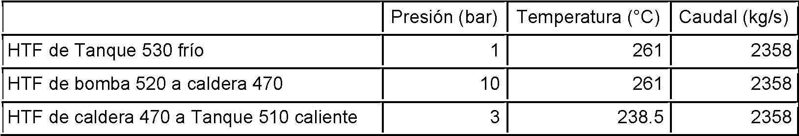
Tabla 3D Fluos HTF entre LTHRU 240 Desaireador 450Table 3D Fluos HTF between LTHRU 240 Deaerator 450


Tabla 3E Flujo de aire a través del condensador 420 enfriado por aire Table 3E Airflow Through the 420 Air-Cooled Condenser

Tabla 3F Funciones de calentamientoTable 3F Heating functions

Tabla 3G Generación y Eficiencia EléctricaTable 3G Electric Generation and Efficiency

Tabla 4 Fluidos de transferencia de calor medios de almacenamiento de calor Table 4 Heat transfer fluids heat storage media


Claims (15)
Applications Claiming Priority (2)
| Application Number | Priority Date | Filing Date | Title |
|---|---|---|---|
| US201562251338P | 2015-11-05 | 2015-11-05 | |
| PCT/US2016/060608 WO2017079617A1 (en) | 2015-11-05 | 2016-11-04 | Dispatchable storage combined cycle power plants |
Publications (1)
| Publication Number | Publication Date |
|---|---|
| ES2940609T3 true ES2940609T3 (en) | 2023-05-09 |
Family
ID=58662921
Family Applications (1)
| Application Number | Title | Priority Date | Filing Date |
|---|---|---|---|
| ES16863071T Active ES2940609T3 (en) | 2015-11-05 | 2016-11-04 | Available Storage Combined Cycle Power Plants |
Country Status (4)
| Country | Link |
|---|---|
| US (3) | US10982570B2 (en) |
| EP (1) | EP3371421B1 (en) |
| ES (1) | ES2940609T3 (en) |
| WO (1) | WO2017079617A1 (en) |
Families Citing this family (45)
| Publication number | Priority date | Publication date | Assignee | Title |
|---|---|---|---|---|
| US10094219B2 (en) | 2010-03-04 | 2018-10-09 | X Development Llc | Adiabatic salt energy storage |
| WO2014052927A1 (en) | 2012-09-27 | 2014-04-03 | Gigawatt Day Storage Systems, Inc. | Systems and methods for energy storage and retrieval |
| WO2016195968A1 (en) | 2015-06-01 | 2016-12-08 | Conlon William M | Part load operation of liquid air power and storage system |
| WO2016195999A1 (en) | 2015-06-03 | 2016-12-08 | Conlon William M | Liquid air power and storage with carbon capture |
| WO2016204893A1 (en) | 2015-06-16 | 2016-12-22 | Conlon William M | Cryogenic liquid energy storage |
| EP3365536B1 (en) | 2015-10-21 | 2020-11-18 | William M. Conlon | High pressure liquid air power and storage |
| US11053847B2 (en) | 2016-12-28 | 2021-07-06 | Malta Inc. | Baffled thermoclines in thermodynamic cycle systems |
| US10233833B2 (en) | 2016-12-28 | 2019-03-19 | Malta Inc. | Pump control of closed cycle power generation system |
| US10233787B2 (en) | 2016-12-28 | 2019-03-19 | Malta Inc. | Storage of excess heat in cold side of heat engine |
| US10458284B2 (en) | 2016-12-28 | 2019-10-29 | Malta Inc. | Variable pressure inventory control of closed cycle system with a high pressure tank and an intermediate pressure tank |
| US10221775B2 (en) | 2016-12-29 | 2019-03-05 | Malta Inc. | Use of external air for closed cycle inventory control |
| US10801404B2 (en) | 2016-12-30 | 2020-10-13 | Malta Inc. | Variable pressure turbine |
| US10436109B2 (en) | 2016-12-31 | 2019-10-08 | Malta Inc. | Modular thermal storage |
| AT520477B1 (en) * | 2017-09-15 | 2019-10-15 | Franz Matthias Schweighofer | Apparatus for generating steam |
| CN109970119B (en) * | 2017-12-28 | 2022-04-15 | 平高集团有限公司 | Clean energy storage and seawater desalination co-production system and method |
| DE102018109846B4 (en) * | 2018-04-24 | 2020-11-19 | Heinrich Graucob | Process for storing electrical energy |
| GB201808478D0 (en) * | 2018-05-23 | 2018-07-11 | Univ Edinburgh | Ultra-high temperature thermal energy storage system |
| CN110886631A (en) * | 2018-09-07 | 2020-03-17 | 上海明华电力技术工程有限公司 | Photo-thermal embedded thermal power peak regulation system and method |
| CN113168923A (en) * | 2018-10-31 | 2021-07-23 | 陆地能源美国公司 | Power station |
| CN109668134B (en) * | 2019-01-30 | 2024-01-02 | 思安新能源股份有限公司 | Start boiler system combining heat storage and release mechanism and electric heating boiler |
| CN116557091A (en) | 2019-11-16 | 2023-08-08 | 马耳他股份有限公司 | Dual power system pumped thermal energy storage with thermal storage medium rebalancing |
| WO2021163065A1 (en) * | 2020-02-10 | 2021-08-19 | Conlon William M | Flexible integration of stored heat and electric resources (fisher) |
| CN111306001B (en) * | 2020-03-02 | 2023-09-08 | 西安交通大学 | Wind-solar reactor system and working method thereof |
| BR112022017503A2 (en) * | 2020-03-09 | 2022-12-20 | Nooter/Eriksen Inc | RENEWABLE ENERGY GENERATION SYSTEM AND METHOD |
| US11081887B1 (en) * | 2020-05-04 | 2021-08-03 | 8Me Nova, Llc | Systems and methods utilizing AC overbuilt renewable electric generation resource and charge storage device providing desired capacity factor |
| US11916383B2 (en) * | 2020-05-04 | 2024-02-27 | 8Me Nova, Llc | Implementing power delivery transaction for potential electrical output of integrated renewable energy source and energy storage system facility |
| US11661857B2 (en) * | 2020-06-16 | 2023-05-30 | Cyrq Energy, Inc. | Electricity generating systems with thermal energy storage coupled superheaters |
| US11454167B1 (en) * | 2020-08-12 | 2022-09-27 | Malta Inc. | Pumped heat energy storage system with hot-side thermal integration |
| US11480067B2 (en) | 2020-08-12 | 2022-10-25 | Malta Inc. | Pumped heat energy storage system with generation cycle thermal integration |
| US11396826B2 (en) | 2020-08-12 | 2022-07-26 | Malta Inc. | Pumped heat energy storage system with electric heating integration |
| US11286804B2 (en) | 2020-08-12 | 2022-03-29 | Malta Inc. | Pumped heat energy storage system with charge cycle thermal integration |
| US11434786B2 (en) * | 2020-08-12 | 2022-09-06 | Mitsubishi Power Americas, Inc. | Combined-cycle power plant with thermal energy storage |
| CN112185602B (en) * | 2020-09-15 | 2023-12-08 | 岭东核电有限公司 | Method and device for nuclear power station standby unit, terminal equipment and storage medium |
| CN112361423B (en) * | 2020-10-30 | 2022-08-23 | 广西电网有限责任公司电力科学研究院 | Low-pressure steam source boosting and heating device of cogeneration unit |
| EP4248068A1 (en) * | 2020-11-23 | 2023-09-27 | Pintail Power LLC | Start-up and control of liquid salt energy storage combined cycle systems |
| US11913362B2 (en) | 2020-11-30 | 2024-02-27 | Rondo Energy, Inc. | Thermal energy storage system coupled with steam cracking system |
| WO2022115721A2 (en) | 2020-11-30 | 2022-06-02 | Rondo Energy, Inc. | Energy storage system and applications |
| US11913361B2 (en) | 2020-11-30 | 2024-02-27 | Rondo Energy, Inc. | Energy storage system and alumina calcination applications |
| CN112761745B (en) * | 2021-01-20 | 2022-06-03 | 中国科学院力学研究所 | Hot water energy storage system and method for thermal generator set |
| EP4124726A1 (en) * | 2021-07-29 | 2023-02-01 | TotalEnergies OneTech | Installation for producing electricity and heat, comprising a gas turbine unit |
| CN113756893A (en) * | 2021-08-27 | 2021-12-07 | 北京工业大学 | Multi-unit combined operation flexibility adjusting system among multiple power plants |
| US11611263B1 (en) * | 2022-04-28 | 2023-03-21 | Sapphire Technologies, Inc. | Electrical power generation |
| CN115254901A (en) * | 2022-07-27 | 2022-11-01 | 西安热工研究院有限公司 | Photovoltaic module recovery system and method combined with thermal power plant |
| US11619379B2 (en) * | 2022-08-16 | 2023-04-04 | Regen Technologies Pte. Ltd. | Solar thermodynamic power generator |
| CN115899660B (en) * | 2023-03-09 | 2023-05-05 | 中国电力工程顾问集团有限公司 | Peak regulating system and method for coal-fired unit |
Family Cites Families (43)
| Publication number | Priority date | Publication date | Assignee | Title |
|---|---|---|---|---|
| US3796045A (en) * | 1971-07-15 | 1974-03-12 | Turbo Dev Inc | Method and apparatus for increasing power output and/or thermal efficiency of a gas turbine power plant |
| US4265223A (en) * | 1978-09-18 | 1981-05-05 | The Badger Company, Inc. | Method and apparatus for utilizing solar energy |
| US5384489A (en) * | 1994-02-07 | 1995-01-24 | Bellac; Alphonse H. | Wind-powered electricity generating system including wind energy storage |
| US5444972A (en) | 1994-04-12 | 1995-08-29 | Rockwell International Corporation | Solar-gas combined cycle electrical generating system |
| DE4434526C1 (en) | 1994-09-27 | 1996-04-04 | Siemens Ag | Process for operating a gas and steam turbine plant and plant operating thereafter |
| DE19757588A1 (en) * | 1996-12-24 | 1998-07-02 | Hitachi Ltd | Electricity generating system with gas turbine and energy storage |
| US6000211A (en) | 1997-06-18 | 1999-12-14 | York Research Corporation | Solar power enhanced combustion turbine power plant and methods |
| DE10056231B4 (en) * | 2000-11-13 | 2012-02-23 | Alstom Technology Ltd. | Method for operating a combined cycle power plant |
| US20070157614A1 (en) | 2003-01-21 | 2007-07-12 | Goldman Arnold J | Hybrid Generation with Alternative Fuel Sources |
| US7191597B2 (en) | 2003-01-21 | 2007-03-20 | Los Angeles Advisory Services, Inc. | Hybrid generation with alternative fuel sources |
| US20060174622A1 (en) | 2005-02-09 | 2006-08-10 | Mark Skowronski | Electrical generating system using solar energy and gas turbine |
| US7640746B2 (en) * | 2005-05-27 | 2010-01-05 | Markon Technologies, LLC | Method and system integrating solar heat into a regenerative rankine steam cycle |
| DE102006035273B4 (en) * | 2006-07-31 | 2010-03-04 | Siegfried Dr. Westmeier | Process for effective and low-emission operation of power plants, as well as for energy storage and energy conversion |
| JP4322902B2 (en) | 2006-08-10 | 2009-09-02 | 川崎重工業株式会社 | Solar power generation equipment and heat medium supply equipment |
| US20080127647A1 (en) | 2006-09-15 | 2008-06-05 | Skyfuel, Inc. | Solar-Generated Steam Retrofit for Supplementing Natural-Gas Combustion at Combined Cycle Power Plants |
| JP4786504B2 (en) * | 2006-11-10 | 2011-10-05 | 川崎重工業株式会社 | Heat medium supply facility, solar combined power generation facility, and control method thereof |
| US7954321B2 (en) * | 2007-03-08 | 2011-06-07 | Research Foundation Of The City University Of New York | Solar power plant and method and/or system of storing energy in a concentrated solar power plant |
| FR2916101B1 (en) * | 2007-05-11 | 2009-08-21 | Saipem Sa | INSTALLATION AND METHODS FOR STORAGE AND RESTITUTION OF ELECTRICAL ENERGY |
| ES2304118B1 (en) | 2008-02-25 | 2009-07-29 | Sener Grupo De Ingenieria, S.A | PROCEDURE FOR GENERATING ENERGY THROUGH THERMAL CYCLES WITH HIGH PRESSURE VAPOR AND MODERATED TEMPERATURE. |
| US8033110B2 (en) | 2008-03-16 | 2011-10-11 | Brightsource Industries (Israel) Ltd. | Solar power generation with multiple energy conversion modes |
| US7971437B2 (en) * | 2008-07-14 | 2011-07-05 | Bell Independent Power Corporation | Thermal energy storage systems and methods |
| DE102008051384B3 (en) | 2008-10-11 | 2010-02-11 | Technische Universität Dresden | Solar-hybrid operated gas and steam power plant has solar plant, gas turbine system and steam turbine system, where heat-carrier circuit is provided for transmitting solar heat |
| US20100229523A1 (en) * | 2009-03-16 | 2010-09-16 | General Electric Company | Continuous combined cycle operation power plant and method |
| US8171733B2 (en) * | 2009-04-15 | 2012-05-08 | General Electric Company | Systems and methods involving combined cycle plants |
| CN102741616B (en) | 2009-05-15 | 2015-04-29 | 阿海珐太阳能公司 | Systems and methods for producing steam using solar radiation |
| US8039984B2 (en) * | 2009-05-21 | 2011-10-18 | Advanced Solar Power Israel Ltd. | System for converting solar radiation into electricity |
| WO2011005923A2 (en) | 2009-07-08 | 2011-01-13 | Areva Solar, Inc. | Solar powered heating system for working fluid |
| US20110100004A1 (en) * | 2009-10-30 | 2011-05-05 | Wael Faisal Al-Mazeedi | Adaptive control of a concentrated solar power-enabled power plant |
| WO2011068880A2 (en) | 2009-12-01 | 2011-06-09 | Areva Solar, Inc. | Utilizing steam and/or hot water generated using solar energy |
| US8327641B2 (en) | 2009-12-01 | 2012-12-11 | General Electric Company | System for generation of power using solar energy |
| WO2011077248A2 (en) * | 2009-12-23 | 2011-06-30 | Goebel, Olaf | Combined cycle solar power generation |
| CH702906A1 (en) * | 2010-03-26 | 2011-09-30 | Alstom Technology Ltd | Method for operating an integrated solar combined cycle power plant and solar combined cycle power plant for implementing the process. |
| US20120102950A1 (en) * | 2010-11-02 | 2012-05-03 | Alliance For Sustainable Energy, Llc. | Solar thermal power plant with the integration of an aeroderivative turbine |
| US9540957B2 (en) * | 2011-05-02 | 2017-01-10 | The Research Foundation Of The City University Of New York | Thermal energy storage for combined cycle power plants |
| JP6038448B2 (en) | 2011-12-16 | 2016-12-07 | 三菱日立パワーシステムズ株式会社 | Solar thermal combined power generation system and solar thermal combined power generation method |
| US8893505B2 (en) * | 2012-02-08 | 2014-11-25 | King Fahd University Of Petroleum And Minerals | Integrated solar-gas turbine cogeneration plant |
| US20140033676A1 (en) | 2012-08-02 | 2014-02-06 | Raymond Pang | Unique method of solar integration in combined cycle power plant |
| JP2014047992A (en) | 2012-08-31 | 2014-03-17 | Hitachi Ltd | Heat storage system and power generating system having the same |
| US9322295B2 (en) * | 2012-10-17 | 2016-04-26 | General Electric Company | Thermal energy storage unit with steam and gas turbine system |
| US10060296B2 (en) * | 2012-11-15 | 2018-08-28 | Kevin Lee Friesth | Quintuple-effect generation multi-cycle hybrid renewable energy system with integrated energy provisioning, storage facilities and amalgamated control system cross-reference to related applications |
| US20140223906A1 (en) * | 2013-02-08 | 2014-08-14 | Skyfuel, Inc. | Solar/gas hybrid power system configurations and methods of use |
| WO2015149124A1 (en) * | 2014-04-01 | 2015-10-08 | Graphite Energy N.V. | Use of stored heat energy in a combined cycle gas turbine power generating system |
| US9816490B2 (en) * | 2014-06-04 | 2017-11-14 | William M. Conlon | Dispatchable solar hybrid power plant |
-
2016
- 2016-11-04 WO PCT/US2016/060608 patent/WO2017079617A1/en active Application Filing
- 2016-11-04 ES ES16863071T patent/ES2940609T3/en active Active
- 2016-11-04 EP EP16863071.3A patent/EP3371421B1/en active Active
-
2018
- 2018-04-30 US US15/966,207 patent/US10982570B2/en active Active
-
2021
- 2021-04-16 US US17/232,486 patent/US11359521B2/en active Active
-
2022
- 2022-06-09 US US17/836,361 patent/US20220325640A1/en active Pending
Also Published As
| Publication number | Publication date |
|---|---|
| US20220325640A1 (en) | 2022-10-13 |
| US11359521B2 (en) | 2022-06-14 |
| US20210324765A1 (en) | 2021-10-21 |
| US10982570B2 (en) | 2021-04-20 |
| EP3371421B1 (en) | 2023-02-15 |
| US20180245485A1 (en) | 2018-08-30 |
| EP3371421A1 (en) | 2018-09-12 |
| WO2017079617A1 (en) | 2017-05-11 |
| EP3371421A4 (en) | 2019-07-17 |
Similar Documents
| Publication | Publication Date | Title |
|---|---|---|
| ES2940609T3 (en) | Available Storage Combined Cycle Power Plants | |
| ES2927226T3 (en) | Managed Solar Hybrid Power Plant | |
| Ahmadi et al. | Efficiency improvement of a steam power plant through solar repowering | |
| US7640746B2 (en) | Method and system integrating solar heat into a regenerative rankine steam cycle | |
| US20140223906A1 (en) | Solar/gas hybrid power system configurations and methods of use | |
| US20080127647A1 (en) | Solar-Generated Steam Retrofit for Supplementing Natural-Gas Combustion at Combined Cycle Power Plants | |
| US20120102950A1 (en) | Solar thermal power plant with the integration of an aeroderivative turbine | |
| ES2525739A1 (en) | High temperature thermal energy storage for grid storage and concentrated solar plant enhancement | |
| EP3130770A1 (en) | Optimized integrated system for solar-biomass hybrid electricity generation | |
| US20080034757A1 (en) | Method and system integrating solar heat into a regenerative rankine cycle | |
| Turchi et al. | Gas turbine/solar parabolic trough hybrid designs | |
| CN104420906B (en) | Steam turbine installation | |
| Li et al. | Impacts of solar multiples on the performance of integrated solar combined cycle systems with two direct steam generation fields | |
| Rech et al. | Optimum integration of concentrating solar technologies in a real coal-fired power plant for fuel saving | |
| US20140182576A1 (en) | System for Improved Hybridization of Thermal Solar and Biomass and Fossil Fuel Based Energy Systems | |
| EP1161617B1 (en) | Method for optimally operating co-generation of electricity and heat and optimally operating district heating power plant | |
| WO2014123537A1 (en) | Solar/gas hybrid power system configurations and methods of use | |
| Mouaky et al. | Energetic, exergetic and exergeoeconomic assessment of a hybrid solar/biomass poylgeneration system: A case study of a rural community in a semi-arid climate | |
| CN107269391A (en) | Comprehensive hospital energy supplying system and its application based on gas turbine | |
| Jensen et al. | Demonstration of a concentrated solar power and biomass plant for combined heat and power | |
| Kopp et al. | Comparison of two-tank indirect thermal storage designs for solar parabolic trough power plants | |
| CN208504515U (en) | A kind of thermoelectricity decoupling heating system using phase-transition heat-storage | |
| EP2718553B1 (en) | Power generation plant and method of operating a power generation plant | |
| CN108800268A (en) | Heating system and method suitable for long range heat supply | |
| Turchi et al. | Gas turbine/solar parabolic trough hybrid design using molten salt heat transfer fluid |