US1009301A - Rotation device for drills. - Google Patents
Rotation device for drills. Download PDFInfo
- Publication number
- US1009301A US1009301A US46815008A US1908468150A US1009301A US 1009301 A US1009301 A US 1009301A US 46815008 A US46815008 A US 46815008A US 1908468150 A US1908468150 A US 1908468150A US 1009301 A US1009301 A US 1009301A
- Authority
- US
- United States
- Prior art keywords
- drill
- drills
- rotation device
- pistons
- piston
- Prior art date
- Legal status (The legal status is an assumption and is not a legal conclusion. Google has not performed a legal analysis and makes no representation as to the accuracy of the status listed.)
- Expired - Lifetime
Links
Images
Classifications
-
- E—FIXED CONSTRUCTIONS
- E21—EARTH DRILLING; MINING
- E21B—EARTH DRILLING, e.g. DEEP DRILLING; OBTAINING OIL, GAS, WATER, SOLUBLE OR MELTABLE MATERIALS OR A SLURRY OF MINERALS FROM WELLS
- E21B6/00—Drives for drilling with combined rotary and percussive action
Definitions
- This invention relates to rotation devices for drills and has for its object to provide a novel rotation device arranged to impart an intermittent movement in one direction to the drill steel and hold it against rotary movement in the opposite direction, the said rotation device including an oscillating member arranged to be clutched'to and released from the drill steel, and a pair of fluid pressure controlled pistons for oscillatin said member.
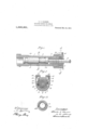
- Figure 1 represents in longitudinal central section so much of a hammer drill as 1 will give a clear understanding of the construction, location and operation of my improved rotation device
- Fig. 2 is a transverse section taken in the plane of the line A--A of Fig. 1, looking in the direction of the arrows
- Fig. 3 is a transverse section taken in the plane of the line B-B of Fig. 1. looking in the direction of the arrows.
- the tool piston 1 is fitted to reciprocate in the cylinder 2 and is arranged to strike the anvil block 8.
- a chuck 4 is rotatably mounted in the front end of the cylinder 2 and is held in position by a front head
- the angular shank of the'drill steel 6 is removably insertedinto the chuck 4 into position to be engaged by the anvil 3.
- An oscillating ring 7 is mounted in the front head 5 and surrounds the chuck 4.
- any device may be employed for clutching and releasing the chuck and oscillating ring, that shown herein being of the well known pawl and ratchet type, in which spring pressed pawls 8 are mounted in the oscillating ring 7 and the chuck 4 is provided with an annular series of ratchetteeth 9.
- the oscillating ring 7 is provided with diametrically opposed wings or abutments 10, 11-, fitted to reciprocate in recesses 12, 13,
- This front head is. further provided with a pair of pistons 14, 15, fitted to reciprocate in the chambers of two cylinders 16, 17, on the front head 5, the rods 18, 19, of which pistons are engaged with the abutments 10, 11, of the oscillating ring 7.
- These oscillating ring operating pistons are reciprocated by the motive fluid which operates the drill and the movements of these-pistons are controlled by the hammer piston 1 as follows :-A passage leads from the chamber of the cylinder 16 at the upper side of the piston 14 to the front end of the hammer piston chamber and a passage 21 leads from the chamber of the cylinder 17 at the upper side of the piston 15 to the rear end of the'hammer piston chamber.
- a front head having two separate pistom chambers on the same side of the front head and two separate recesses, a drill, a member for rotating the drill having diametrically opposed abutments fittedto oscillate in said recesses and pistons fitted to reciprocate in said chambers and engaged with said abutments.
- a front head having two separate piston chambers on the same side of the front head and two separate recesses, a drill, a member for rotatingthe drill having diametrically opposed abutments fitted to oscillate insaid recesses, pistons fitted to reciprocate in said chambers and 'iston rodsextending from the pistoneham ers into the recesses and engaged with said abutments 3.
- a main cylinder its piston, a front head having two separate auxiliarypiston chambers on the same side ofthe front'head, and two recesses, passages leading from the main piston chamber to the separate auxiliary piston chambers, a drill, a member for rotating the drill having diametrically opposed abutpresence of two Witnesses, this 15th day of ments' fitted to oscillate in said l'evesses and December 1908.
Description
0. 0. HANSEN. ROTATION DEV -ICE FOR DRILLS.
APPLICATION FILED DEG. 18,1908.
. Patented Nov. 21, 1911.
UNITED STAigliSgPiiTENT OFFICE.
CHARLES C. HANSEN, OF EASTON, PENNSYLVANIA, ASSIGNOR TO INGERSOLL-RAND COMPANY, OF NEW YORK, N. Y., A CORPORATION OF NEW JERSEY.
ROTATION DEVICE- FOR DRILLS 'l'o oil whom it may concern:
Be it known that I, CHARLES C. HANSEN, a citizen of the United States, and resident of Easton, in the county of Northampton and State of Pennsylvania, have invented a new and useful Rotation Device for Drills, of which the following is a specification.
.This invention relates to rotation devices for drills and has for its object to provide a novel rotation device arranged to impart an intermittent movement in one direction to the drill steel and hold it against rotary movement in the opposite direction, the said rotation device including an oscillating member arranged to be clutched'to and released from the drill steel, and a pair of fluid pressure controlled pistons for oscillatin said member.
A practical embodiment of my invention is represented in the accompanying drawings, in which the invention is shown in connectionwith a hammer drill.
Figure 1 represents in longitudinal central section so much of a hammer drill as 1 will give a clear understanding of the construction, location and operation of my improved rotation device, Fig. 2 is a transverse section taken in the plane of the line A--A of Fig. 1, looking in the direction of the arrows, and Fig. 3 is a transverse section taken in the plane of the line B-B of Fig. 1. looking in the direction of the arrows.
The tool piston 1 is fitted to reciprocate in the cylinder 2 and is arranged to strike the anvil block 8. A chuck 4 is rotatably mounted in the front end of the cylinder 2 and is held in position by a front head The angular shank of the'drill steel 6 is removably insertedinto the chuck 4 into position to be engaged by the anvil 3. An oscillating ring 7 is mounted in the front head 5 and surrounds the chuck 4.
Any device may be employed for clutching and releasing the chuck and oscillating ring, that shown herein being of the well known pawl and ratchet type, in which spring pressed pawls 8 are mounted in the oscillating ring 7 and the chuck 4 is provided with an annular series of ratchetteeth 9. The oscillating ring 7 is provided with diametrically opposed wings or abutments 10, 11-, fitted to reciprocate in recesses 12, 13,
Specification of Letters Patent. Patented Nov, 21, 1911, Application filed December 18, 1908. Serial No. 468,150. 1
in the front head 5. This front head is. further provided with a pair of pistons 14, 15, fitted to reciprocate in the chambers of two cylinders 16, 17, on the front head 5, the rods 18, 19, of which pistons are engaged with the abutments 10, 11, of the oscillating ring 7. These oscillating ring operating pistons are reciprocated by the motive fluid which operates the drill and the movements of these-pistons are controlled by the hammer piston 1 as follows :-A passage leads from the chamber of the cylinder 16 at the upper side of the piston 14 to the front end of the hammer piston chamber and a passage 21 leads from the chamber of the cylinder 17 at the upper side of the piston 15 to the rear end of the'hammer piston chamber.
In operation, as the hammer piston 1 is reciprocated, it will open and close the passages 20, 21, leading to the oscillating ring operating pistons 14, 15, thus reciprocating these pistons i l, 15, and because of their engagement with the abutments 10, 11, of the oscillating ring, will operate the said ring.
' What I claim is 1. In a device of the character described,
a front head having two separate pistom chambers on the same side of the front head and two separate recesses, a drill, a member for rotating the drill having diametrically opposed abutments fittedto oscillate in said recesses and pistons fitted to reciprocate in said chambers and engaged with said abutments.
2. Ina device of the character described, a front head having two separate piston chambers on the same side of the front head and two separate recesses, a drill, a member for rotatingthe drill having diametrically opposed abutments fitted to oscillate insaid recesses, pistons fitted to reciprocate in said chambers and 'iston rodsextending from the pistoneham ers into the recesses and engaged with said abutments 3. In a device of the character described, a main cylinder, its piston, a front head having two separate auxiliarypiston chambers on the same side ofthe front'head, and two recesses, passages leading from the main piston chamber to the separate auxiliary piston chambers, a drill, a member for rotating the drill having diametrically opposed abutpresence of two Witnesses, this 15th day of ments' fitted to oscillate in said l'evesses and December 1908. I
msfnns fitted (0 1n [p1 (n ate 1n saw a uuhln CHARLES C. HANSEN pls-tun chambersand engaged wlfh sald 0 5 abutments.
In testimony, that I claim the foregoing as my lnventmn, T have slgned my name In Witnesses ARTHUR J. SHIMER, H. A. GINLEY.
Priority Applications (1)
| Application Number | Priority Date | Filing Date | Title |
|---|---|---|---|
| US46815008A US1009301A (en) | 1908-12-18 | 1908-12-18 | Rotation device for drills. |
Applications Claiming Priority (1)
| Application Number | Priority Date | Filing Date | Title |
|---|---|---|---|
| US46815008A US1009301A (en) | 1908-12-18 | 1908-12-18 | Rotation device for drills. |
Publications (1)
| Publication Number | Publication Date |
|---|---|
| US1009301A true US1009301A (en) | 1911-11-21 |
Family
ID=3077611
Family Applications (1)
| Application Number | Title | Priority Date | Filing Date |
|---|---|---|---|
| US46815008A Expired - Lifetime US1009301A (en) | 1908-12-18 | 1908-12-18 | Rotation device for drills. |
Country Status (1)
| Country | Link |
|---|---|
| US (1) | US1009301A (en) |
Cited By (2)
| Publication number | Priority date | Publication date | Assignee | Title |
|---|---|---|---|---|
| US2457969A (en) * | 1947-03-28 | 1949-01-04 | Ingersoll Rand Co | Rotation device for rock drills |
| US3434387A (en) * | 1965-03-09 | 1969-03-25 | Elliott Brothers London Ltd | Hydraulic actuators |
-
1908
- 1908-12-18 US US46815008A patent/US1009301A/en not_active Expired - Lifetime
Cited By (2)
| Publication number | Priority date | Publication date | Assignee | Title |
|---|---|---|---|---|
| US2457969A (en) * | 1947-03-28 | 1949-01-04 | Ingersoll Rand Co | Rotation device for rock drills |
| US3434387A (en) * | 1965-03-09 | 1969-03-25 | Elliott Brothers London Ltd | Hydraulic actuators |
Similar Documents
| Publication | Publication Date | Title |
|---|---|---|
| US1009301A (en) | Rotation device for drills. | |
| US1141650A (en) | Jack hammer-drill. | |
| US1097997A (en) | Rotation device for fluid-pressure-operated-hammer tools. | |
| US592115A (en) | Charles h | |
| US2597574A (en) | Percussion tool | |
| US2108989A (en) | Rotation mechanism | |
| US2129566A (en) | Fluid operated tool | |
| US1390787A (en) | Drilling-machine | |
| US490152A (en) | Clutch for rock-drilling machines | |
| US47819A (en) | Improved drilling and boring machine | |
| US1142478A (en) | Percussive tool. | |
| US1023518A (en) | Rotation device for hammer-drills. | |
| US1080095A (en) | Percussive tool. | |
| US2336953A (en) | Rock drill | |
| US1314246A (en) | clark | |
| US799406A (en) | Pneumatic rock-drill. | |
| US971638A (en) | Air or steam rock-drill. | |
| US951465A (en) | Rotation device for fluid-pressure-operated-hammer tools. | |
| US894213A (en) | Rock-drill. | |
| US1176443A (en) | Percussive tool. | |
| US1081653A (en) | Percussive tool. | |
| US1089038A (en) | Percussive tool. | |
| US1074116A (en) | Rotary percussive tool. | |
| US1588408A (en) | Drilling machine | |
| US1588406A (en) | Drilling machine |