US10082272B2 - Bi-function lighting module made of transparent material - Google Patents
Bi-function lighting module made of transparent material Download PDFInfo
- Publication number
- US10082272B2 US10082272B2 US15/680,297 US201715680297A US10082272B2 US 10082272 B2 US10082272 B2 US 10082272B2 US 201715680297 A US201715680297 A US 201715680297A US 10082272 B2 US10082272 B2 US 10082272B2
- Authority
- US
- United States
- Prior art keywords
- module according
- optical axis
- reflection
- cut
- input surface
- Prior art date
- Legal status (The legal status is an assumption and is not a legal conclusion. Google has not performed a legal analysis and makes no representation as to the accuracy of the status listed.)
- Active
Links
Images


Classifications
-
- F—MECHANICAL ENGINEERING; LIGHTING; HEATING; WEAPONS; BLASTING
- F21—LIGHTING
- F21V—FUNCTIONAL FEATURES OR DETAILS OF LIGHTING DEVICES OR SYSTEMS THEREOF; STRUCTURAL COMBINATIONS OF LIGHTING DEVICES WITH OTHER ARTICLES, NOT OTHERWISE PROVIDED FOR
- F21V13/00—Producing particular characteristics or distribution of the light emitted by means of a combination of elements specified in two or more of main groups F21V1/00 - F21V11/00
- F21V13/02—Combinations of only two kinds of elements
- F21V13/04—Combinations of only two kinds of elements the elements being reflectors and refractors
-
- F—MECHANICAL ENGINEERING; LIGHTING; HEATING; WEAPONS; BLASTING
- F21—LIGHTING
- F21S—NON-PORTABLE LIGHTING DEVICES; SYSTEMS THEREOF; VEHICLE LIGHTING DEVICES SPECIALLY ADAPTED FOR VEHICLE EXTERIORS
- F21S41/00—Illuminating devices specially adapted for vehicle exteriors, e.g. headlamps
- F21S41/10—Illuminating devices specially adapted for vehicle exteriors, e.g. headlamps characterised by the light source
- F21S41/14—Illuminating devices specially adapted for vehicle exteriors, e.g. headlamps characterised by the light source characterised by the type of light source
- F21S41/141—Light emitting diodes [LED]
- F21S41/147—Light emitting diodes [LED] the main emission direction of the LED being angled to the optical axis of the illuminating device
-
- F—MECHANICAL ENGINEERING; LIGHTING; HEATING; WEAPONS; BLASTING
- F21—LIGHTING
- F21S—NON-PORTABLE LIGHTING DEVICES; SYSTEMS THEREOF; VEHICLE LIGHTING DEVICES SPECIALLY ADAPTED FOR VEHICLE EXTERIORS
- F21S41/00—Illuminating devices specially adapted for vehicle exteriors, e.g. headlamps
- F21S41/10—Illuminating devices specially adapted for vehicle exteriors, e.g. headlamps characterised by the light source
- F21S41/14—Illuminating devices specially adapted for vehicle exteriors, e.g. headlamps characterised by the light source characterised by the type of light source
- F21S41/141—Light emitting diodes [LED]
- F21S41/151—Light emitting diodes [LED] arranged in one or more lines
-
- F—MECHANICAL ENGINEERING; LIGHTING; HEATING; WEAPONS; BLASTING
- F21—LIGHTING
- F21S—NON-PORTABLE LIGHTING DEVICES; SYSTEMS THEREOF; VEHICLE LIGHTING DEVICES SPECIALLY ADAPTED FOR VEHICLE EXTERIORS
- F21S41/00—Illuminating devices specially adapted for vehicle exteriors, e.g. headlamps
- F21S41/20—Illuminating devices specially adapted for vehicle exteriors, e.g. headlamps characterised by refractors, transparent cover plates, light guides or filters
- F21S41/24—Light guides
-
- F—MECHANICAL ENGINEERING; LIGHTING; HEATING; WEAPONS; BLASTING
- F21—LIGHTING
- F21S—NON-PORTABLE LIGHTING DEVICES; SYSTEMS THEREOF; VEHICLE LIGHTING DEVICES SPECIALLY ADAPTED FOR VEHICLE EXTERIORS
- F21S41/00—Illuminating devices specially adapted for vehicle exteriors, e.g. headlamps
- F21S41/20—Illuminating devices specially adapted for vehicle exteriors, e.g. headlamps characterised by refractors, transparent cover plates, light guides or filters
- F21S41/25—Projection lenses
- F21S41/26—Elongated lenses
-
- F—MECHANICAL ENGINEERING; LIGHTING; HEATING; WEAPONS; BLASTING
- F21—LIGHTING
- F21S—NON-PORTABLE LIGHTING DEVICES; SYSTEMS THEREOF; VEHICLE LIGHTING DEVICES SPECIALLY ADAPTED FOR VEHICLE EXTERIORS
- F21S41/00—Illuminating devices specially adapted for vehicle exteriors, e.g. headlamps
- F21S41/20—Illuminating devices specially adapted for vehicle exteriors, e.g. headlamps characterised by refractors, transparent cover plates, light guides or filters
- F21S41/25—Projection lenses
- F21S41/265—Composite lenses; Lenses with a patch-like shape
-
- F—MECHANICAL ENGINEERING; LIGHTING; HEATING; WEAPONS; BLASTING
- F21—LIGHTING
- F21S—NON-PORTABLE LIGHTING DEVICES; SYSTEMS THEREOF; VEHICLE LIGHTING DEVICES SPECIALLY ADAPTED FOR VEHICLE EXTERIORS
- F21S41/00—Illuminating devices specially adapted for vehicle exteriors, e.g. headlamps
- F21S41/30—Illuminating devices specially adapted for vehicle exteriors, e.g. headlamps characterised by reflectors
- F21S41/32—Optical layout thereof
- F21S41/322—Optical layout thereof the reflector using total internal reflection
-
- F—MECHANICAL ENGINEERING; LIGHTING; HEATING; WEAPONS; BLASTING
- F21—LIGHTING
- F21S—NON-PORTABLE LIGHTING DEVICES; SYSTEMS THEREOF; VEHICLE LIGHTING DEVICES SPECIALLY ADAPTED FOR VEHICLE EXTERIORS
- F21S41/00—Illuminating devices specially adapted for vehicle exteriors, e.g. headlamps
- F21S41/30—Illuminating devices specially adapted for vehicle exteriors, e.g. headlamps characterised by reflectors
- F21S41/32—Optical layout thereof
- F21S41/36—Combinations of two or more separate reflectors
- F21S41/365—Combinations of two or more separate reflectors successively reflecting the light
-
- F—MECHANICAL ENGINEERING; LIGHTING; HEATING; WEAPONS; BLASTING
- F21—LIGHTING
- F21S—NON-PORTABLE LIGHTING DEVICES; SYSTEMS THEREOF; VEHICLE LIGHTING DEVICES SPECIALLY ADAPTED FOR VEHICLE EXTERIORS
- F21S41/00—Illuminating devices specially adapted for vehicle exteriors, e.g. headlamps
- F21S41/40—Illuminating devices specially adapted for vehicle exteriors, e.g. headlamps characterised by screens, non-reflecting members, light-shielding members or fixed shades
- F21S41/43—Illuminating devices specially adapted for vehicle exteriors, e.g. headlamps characterised by screens, non-reflecting members, light-shielding members or fixed shades characterised by the shape thereof
-
- F—MECHANICAL ENGINEERING; LIGHTING; HEATING; WEAPONS; BLASTING
- F21—LIGHTING
- F21V—FUNCTIONAL FEATURES OR DETAILS OF LIGHTING DEVICES OR SYSTEMS THEREOF; STRUCTURAL COMBINATIONS OF LIGHTING DEVICES WITH OTHER ARTICLES, NOT OTHERWISE PROVIDED FOR
- F21V3/00—Globes; Bowls; Cover glasses
-
- F—MECHANICAL ENGINEERING; LIGHTING; HEATING; WEAPONS; BLASTING
- F21—LIGHTING
- F21V—FUNCTIONAL FEATURES OR DETAILS OF LIGHTING DEVICES OR SYSTEMS THEREOF; STRUCTURAL COMBINATIONS OF LIGHTING DEVICES WITH OTHER ARTICLES, NOT OTHERWISE PROVIDED FOR
- F21V5/00—Refractors for light sources
- F21V5/04—Refractors for light sources of lens shape
-
- F—MECHANICAL ENGINEERING; LIGHTING; HEATING; WEAPONS; BLASTING
- F21—LIGHTING
- F21V—FUNCTIONAL FEATURES OR DETAILS OF LIGHTING DEVICES OR SYSTEMS THEREOF; STRUCTURAL COMBINATIONS OF LIGHTING DEVICES WITH OTHER ARTICLES, NOT OTHERWISE PROVIDED FOR
- F21V7/00—Reflectors for light sources
- F21V7/04—Optical design
- F21V7/06—Optical design with parabolic curvature
-
- G—PHYSICS
- G02—OPTICS
- G02B—OPTICAL ELEMENTS, SYSTEMS OR APPARATUS
- G02B27/00—Optical systems or apparatus not provided for by any of the groups G02B1/00 - G02B26/00, G02B30/00
- G02B27/30—Collimators
Definitions
- the invention relates to the field of lighting, notably for motor vehicles.
- the published patent document EP 1 715 245 A1 discloses a lighting module forming a lighting beam having a cut-off.
- the module comprises a body made of transparent material with an input surface, a first reflection surface, a second reflection surface with a cut-off edge and an output surface.
- the first and second reflection surfaces form diopters with the ambient air and thus allow rays to undergo reflection on them by application of the total reflection principle.
- This module is advantageous in that is assembles, in the same body, a collimator, a reflector, a folder and a lens, and thus provides a lighting function with a cut-off.
- This module however allows only a single lighting function, in this instance a lighting with a cut-off function.
- the purpose of the invention is to overcome at least one of the disadvantages of the abovementioned prior art. More particularly, the purpose of the invention is to propose a lighting module comprising a body made of transparent or translucent material and which is able to provide several lighting functions.
- the invention relates to a lighting module for a motor vehicle, the module being able to form a light beam along an optical axis, and comprising a body made of transparent or translucent material, the said body comprising a first light rays input surface; a first reflection surface able to reflect to one or more focuses the light rays coming from the first input surface; a dioptric reflection folder surface essentially extending along the optical axis and forming a cut-off edge at the level of the focus or focuses and a light rays output surface; noteworthy in that the body furthermore comprises a second light rays input surface, opposite to the first input surface with respect to the optical axis, and a second reflection surface able to reflect the light rays coming from the second input surface towards the cut-off edge, the body forming a cavity with a bottom formed by the dioptric reflection surface, the said cavity being able to be traversed by the rays coming from the second reflection surface.
- the optical axis advantageously passes into the folder surface.
- the cavity is located, with respect to the optical axis, on the same side as the second input surface and the second reflection surface.
- the cavity has a U-shaped cross-section in a longitudinal plane passing through the optical axis.
- the cavity comprises, in addition to the bottom surface, a front surface and a rear surface, the said front surface being adjacent to the bottom surface at the level of the cut-off edge.
- the module is configured such that the light rays coming from the second reflection surface are able to pass through the rear and front surfaces, the said surfaces forming diopters.
- the diopters are formed with the ambient air.
- the said module extends transversely with respect to the optical axis, preferably following a curved profile.
- the second input surface and the second reflection surface extend transversely with respect to the optical axis over only a portion of the first input surface and of the first reflection surface, the said portion preferably being between 20% and 80%.
- the focus or focuses extend or are distributed transversely with respect to the optical axis along the cut-off edge.
- the cavity is open towards the exterior and contains a material having a refractive index less than that of the transparent or translucent material, such as for example the ambient air.
- the first reflection surface and/or the second reflection surface has a parabolic profile.
- the parabolic profile of the second reflection surface can comprise a focus or several focuses corresponding to the focus or focuses of the first reflection surface, respectively.
- the first input surface and/or the second input surface comprises at least one optical collimating element, preferably one or more collimators.
- the collimator or each of the collimators of the first input surface and/or of the second input surface has a collimation axis, the said axis or each of the said axes being inclined with respect to a plane perpendicular to the optical axis.
- the inclination of the collimation axis or each of the collimation axes is between 5° and 40°, preferably between 7° and 30°, more preferably between 8° and 15°.
- the first input surface, the first reflection surface, the dioptric reflection surface and the output surface are configured in order to form a beam with a horizontal cut-off of the low beam type
- the second input surface, the second reflection surface and the output surface are configured for forming, in combination with the beam having a horizontal cut-off of the low beam type, a high beam.
- the module comprises moreover a projection lens disposed at the front, according to the direction of propagation of the rays, of the output surface of the body.
- the module comprises a body made of transparent or translucent material, preferably in one piece, forming the input surfaces, the reflection surfaces and the output surface.
- the reflection surfaces are advantageously dioptric, that is to say providing the reflection of the light rays by the principle of total reflection. Thus is notably the case for the folder surface.
- Such reflection surfaces have a double advantage, namely that they do not require the application of a reflective coating and that they have better optical efficiency.
- FIG. 1 is a first representation in perspective of a module according to the invention
- FIG. 2 is a second representation in perspective of the module shown in FIG. 1 ;
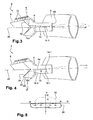
- FIG. 3 is a side view of the module shown in FIGS. 1 and 2 , illustrating the path of light rays according to a first lighting function;
- FIG. 4 is side view of the module shown in FIGS. 1 and 2 , illustrating the path of light rays according to a second lighting function;
- FIG. 5 shows the light images of the first and second lighting functions shown in FIGS. 3 and 4 .
- FIGS. 1 and 2 illustrate in perspective a lighting module according to the invention.
- the module 2 essentially comprises a body 4 made of transparent or translucent material and a projection lens 6 .
- the latter is represented diagrammatically by its input and output surfaces. Moreover, it is not obligatory.
- the body 4 can be made of plastic, such as poly(methyl methacrylate) (PMMA), or of glass.
- the body 4 comprises a first input surface 8 for light rays emitted by one or more light sources (not shown).
- the input surface 8 can comprise one or more collimators 10 facing which the light sources (not shown) are disposed.
- the body 4 also comprises a first reflection surface 12 for rays coming from the input surface 8 , the said surface reflecting the said rays towards a folder 14 .
- the latter is formed by a surface 14 of the body 4 . Plus precisely, the body 4 forms a cavity 16 whose bottom corresponds to the folder surface 14 in question.
- the cavity 16 is open towards the exterior and is advantageously empty of solid matter, that is to say it is filled with the ambient air.
- the cavity can be filled with a material other than air, whose refractive index is less than that of the transparent or translucent material of the body 4 .
- the folder surface 14 thus forms a diopter between the transparent or translucent material of the body 4 and the air in the cavity 16 , the refractive index of the said transparent or translucent material being greater than that of the air.
- the folder surface 14 is thus able to reflect, by the principle of total reflection, the light rays coming from the first reflection surface 12 and encountering this surface.
- the first reflection surface 12 is configured for reflecting the major part of the light rays towards the front edge 14 . 1 of the folder surface 14 .
- the first reflection surface 12 advantageously has a parabolic profile with a focus located on the cut-off edge 14 . 1 .
- the body 4 also comprises an output surface 18 for the light rays for the purpose of forming a lighting beam.
- the output surface 18 can be joined to the projection lens 6 .
- the body also comprises a second input surface 20 advantageously provided with one or more collimators 22 , in a way similar to that of the first input surface 8 .
- the second input surface 20 is opposite the first input surface 8 with respect to the optical axis 26 of the module.
- the body 4 also comprises a second reflection surface 24 , also opposite the first reflection surface 12 with respect to the optical axis 26 .
- the profiles of the first and second input and reflection surfaces can advantageously be at least essentially symmetrical with respect to the optical axis 26 . Unlike the rays propagating from the first reflection surface 12 to the folder surface 14 through a continuity of transparent material, the rays coming from the second reflection surface 24 and propagating to the cut-off edge 14 . 1 leave the body 4 through the rear surface 16 .
- the beam thus produced does not have a cut-off considering that the surface face 14 does not reflect the rays propagating in the groove towards the said face but refracts them. This difference is due to the fact that the refractive index of the ambient air in the groove in which the incident ray propagates is less than the refractive index of the transparent or translucent material of the body 4 .
- the module 2 in this instance the body 2 and the projection lens 6 extend transversely with respect to the optical axis 26 , in this instance according to an arc of circle.
- the second input 20 and reflection 24 surfaces can extend, transversely, only over a portion of the first input 8 and reflection 12 surfaces. This portion can be between 20% and 80%. It is however also possible for the extents of the first and second input and reflection surfaces to be essentially identical.
- FIG. 3 is a side view of the module shown in FIGS. 1 and 2 , illustrating the path of three types of rays emitted by the light sources disposed facing the first input surface 8 .
- a first ray shown in continuous line, is reflected by the first reflection surface 12 towards the cut-off edge 14 . 1 in such a way as to pass in font to this edge and not to undergo any reflection there.
- This ray leaves the body 4 through the output surface 18 and passes through the projection lens 6 and then propagates essentially parallel with the optical axis 26 .
- a second ray shown in dashed line, encounters the first reflection surface 12 at an angle of incidence larger than that of the first ray. It is then reflected towards the folder surface 14 and there undergoes a reflection towards the top part of the body 4 and of the projection lens 6 . This ray leaves the projection lens 6 with a direction slightly downward inclined with respect to the optical axis 26 .
- a third ray shown in axis type line (dash-dot-dash), encounters the first reflection surface 12 at an angle incidence smaller than that of the first ray.
- ray passes in front of the cut-off edge 14 . 1 , at a distance from that edge, and leaves the projection lens 6 with a slightly downward inclined direction with respect to the optical axis 26 .
- the folder surface 14 ensures a good cut-off, in this instance horizontal, of the light beam produced.
- the functional principle of a folder is itself well known to those skilled in the art.
- the folder has the feature of being formed by the diopter formed by the surface 14 . This signifies that this surface can remain transparent and does not require the application of a reflective layer, the reflection taking place according to the principle of total reflection.
- the axis of collimation of the collimator or collimators 10 can be inclined towards the rear (with respect to the direction of travel of the rays) by an angle ⁇ with a plane perpendicular to the optical axis 26 .
- the angle ⁇ can be between 5° and 40°, preferably between 5° and 30°, more preferably between 7° and 30° and even more preferably between 8° and 15°. Such an inclination makes it possible to increase the optical efficiency.
- FIG. 4 is a side view of the module shown in FIGS. 1 and 2 , illustrating the path of a light ray emitted by the light sources disposed facing the second input surface 20 .
- the emitted ray coming from the input surface 20 is reflected by the second reflecting surface 24 towards the rear surface 16 . 2 (with respect to the direction of travel of the rays) of the groove 16 and then leaves the body 4 and passes at least partially through the groove 16 .
- the ray then enters the body again through the front face 16 . 1 (with respect to the direction of travel of the rays) of the groove 16 in order to pass at the level of or at least close to the cut-off edge 14 . 1 of the folder surface 14 .
- the second reflecting surface 24 is advantageously configured for converging the rays towards the cut-off edge 14 . 1 .
- the rays leave essentially from the upper part of the projection lens in the direction of the optical axis 26 and thus form a beam illuminating mostly above the optical axis in question.
- This beam can be added to the cut-off beam produced by the light sources of the first input surface 8 ( FIG. 3 ) for the purpose of forming a so-called high beam or main beam.
- the axis of collimation of the collimator or collimators 22 can be inclined towards the rear (with respect to the direction of travel of the rays) by an angle ⁇ with the plane perpendicular to the optical axis 26 .
- the angle ⁇ can be between 5° and 40°, preferably between 5° and 30°, more preferably between 7° and 30° and even more preferably between 8° and 15°. Such an inclination makes it possible to increase the optical efficiency.
- FIG. 5 is a diagrammatic illustration of the light images produced by the beams described with reference to FIGS. 3 and 4 .
- the axis H corresponds to the horizontal passing through the optical axis of the module.
- the axis V corresponds to the vertical and passes through the optical axis of the module.
- the FIGS. 10, 20, 30 ) on the axes H and V represent the amounts of deflection in degrees with respect to the optical axis. It can be seen that the light image 28 produced by the cut-off beam, described in detail with reference to FIG. 3 , provides illumination essentially below the horizontal axis whereas the light image 30 produced by the beam described in detail with reference to FIG. 4 provides illumination mostly above the horizontal axis.
- the superimposition of the light images 28 and 30 can correspond to so called high beam or main beam lighting.
- the light images which have just been commented upon with reference to FIG. 5 can be shifted horizontally, that is to say along the H axis, notably when several, preferably two, lighting modules are configured for cooperating in producing a combined lighting beam, in which case it can be desirable for one of the modules to illuminate more on one side (laterally) and for the other one of the said modules to illuminate more on the opposite side.
Landscapes
- Engineering & Computer Science (AREA)
- General Engineering & Computer Science (AREA)
- Physics & Mathematics (AREA)
- Optics & Photonics (AREA)
- Microelectronics & Electronic Packaging (AREA)
- General Physics & Mathematics (AREA)
- Lenses (AREA)
- Non-Portable Lighting Devices Or Systems Thereof (AREA)
- Optical Elements Other Than Lenses (AREA)
Abstract
Description
Claims (20)
Priority Applications (1)
| Application Number | Priority Date | Filing Date | Title |
|---|---|---|---|
| US16/105,507 US10344949B2 (en) | 2016-09-26 | 2018-08-20 | Bi-function lighting module made of transparent material |
Applications Claiming Priority (2)
| Application Number | Priority Date | Filing Date | Title |
|---|---|---|---|
| FR1659001A FR3056688B1 (en) | 2016-09-26 | 2016-09-26 | BI-FUNCTION LIGHTING MODULE IN TRANSPARENT MATERIAL |
| FR1659001 | 2016-09-26 |
Related Child Applications (1)
| Application Number | Title | Priority Date | Filing Date |
|---|---|---|---|
| US16/105,507 Continuation US10344949B2 (en) | 2016-09-26 | 2018-08-20 | Bi-function lighting module made of transparent material |
Publications (2)
| Publication Number | Publication Date |
|---|---|
| US20180087745A1 US20180087745A1 (en) | 2018-03-29 |
| US10082272B2 true US10082272B2 (en) | 2018-09-25 |
Family
ID=57396667
Family Applications (2)
| Application Number | Title | Priority Date | Filing Date |
|---|---|---|---|
| US15/680,297 Active US10082272B2 (en) | 2016-09-26 | 2017-08-18 | Bi-function lighting module made of transparent material |
| US16/105,507 Active US10344949B2 (en) | 2016-09-26 | 2018-08-20 | Bi-function lighting module made of transparent material |
Family Applications After (1)
| Application Number | Title | Priority Date | Filing Date |
|---|---|---|---|
| US16/105,507 Active US10344949B2 (en) | 2016-09-26 | 2018-08-20 | Bi-function lighting module made of transparent material |
Country Status (4)
| Country | Link |
|---|---|
| US (2) | US10082272B2 (en) |
| EP (1) | EP3299703B1 (en) |
| CN (1) | CN108302473B (en) |
| FR (1) | FR3056688B1 (en) |
Cited By (10)
| Publication number | Priority date | Publication date | Assignee | Title |
|---|---|---|---|---|
| WO2021136235A1 (en) * | 2020-01-02 | 2021-07-08 | 法雷奥照明公司 | Light guide component, lighting apparatus and vehicle |
| WO2021179664A1 (en) * | 2020-03-09 | 2021-09-16 | 华域视觉科技(上海)有限公司 | Vehicle light optical element assembly, vehicle lighting device, vehicle light and vehicle |
| US11274802B2 (en) | 2018-05-04 | 2022-03-15 | HELLA GmbH & Co. KGaA | Projection headlight |
| WO2022171693A1 (en) * | 2021-02-09 | 2022-08-18 | Valeo Vision | Light emitting module for vehicle, vehicle headlamp and vehicle |
| US20230073488A1 (en) * | 2021-09-08 | 2023-03-09 | Sl Corporation | Vehicle lamp |
| US20240077185A1 (en) * | 2021-05-31 | 2024-03-07 | HELLA GmbH & Co. KGaA | Lighting module and lighting method for generating two different lighting effects |
| US12044375B1 (en) * | 2023-01-06 | 2024-07-23 | Hyundai Mobis Co., Ltd. | Lamp and lamp assembly for vehicle |
| US12194911B2 (en) * | 2022-12-08 | 2025-01-14 | Sl Corporation | Vehicle lamp |
| US20250222855A1 (en) * | 2022-03-14 | 2025-07-10 | Stanley Electric Co., Ltd. | Vehicle lamp |
| US20260063266A1 (en) * | 2024-09-04 | 2026-03-05 | Hyundai Mobis Co., Ltd. | Lamp for vehicle |
Families Citing this family (30)
| Publication number | Priority date | Publication date | Assignee | Title |
|---|---|---|---|---|
| DE102016125887A1 (en) * | 2016-12-29 | 2018-07-05 | Automotive Lighting Reutlingen Gmbh | Light module for motor vehicle headlights |
| CZ201793A3 (en) | 2017-02-17 | 2018-08-29 | Varroc Lighting Systems, s.r.o. | A lighting device, in particular a signal lamp for motor vehicles |
| CN108397746B (en) | 2018-04-13 | 2024-06-14 | 华域视觉科技(上海)有限公司 | Far and near light system and car light based on light guide |
| US10760756B2 (en) * | 2018-07-06 | 2020-09-01 | H.A. Automotive Systems, Inc. | Condenser for low-beam vehicle light module |
| FR3084755B1 (en) * | 2018-08-02 | 2020-12-18 | Valeo Vision | OPTICAL PART INCLUDING A BLOCK WITH A BENDING DIOPTER FOR TWO BEAMS |
| FR3086728B1 (en) * | 2018-09-28 | 2021-07-30 | Valeo Vision | BIFUNCTIONAL SIGNALING AND LIGHTING OPTICAL UNIT |
| KR102558734B1 (en) * | 2018-12-26 | 2023-07-25 | 에스엘 주식회사 | lamp for vehicle |
| US11629831B2 (en) | 2019-01-29 | 2023-04-18 | Hasco Vision Technology Co., Ltd. | Vehicle lamp illumination module, vehicle lamp and vehicle |
| WO2020173444A1 (en) * | 2019-02-25 | 2020-09-03 | 华域视觉科技(上海)有限公司 | High and low beam integrated vehicle lamp lighting device, vehicle lamp, and vehicle |
| CN209801362U (en) * | 2019-03-29 | 2019-12-17 | 曼德电子电器有限公司 | vehicle dipped beam light distribution structure |
| CN112050162A (en) * | 2019-06-05 | 2020-12-08 | 华域视觉科技(上海)有限公司 | Car light optical element, car light module and vehicle |
| US11781733B2 (en) | 2019-06-05 | 2023-10-10 | Hasco Vision Technology Co., Ltd. | Vehicle lamp optical element, vehicle lamp module, vehicle headlamp and vehicle |
| FR3097979B1 (en) | 2019-06-28 | 2021-06-11 | Valeo Vision | Optical part intended to operate in total internal reflection |
| CN210601445U (en) * | 2019-10-25 | 2020-05-22 | 华域视觉科技(上海)有限公司 | Optical element of car lamp |
| CN210740266U (en) * | 2019-10-25 | 2020-06-12 | 华域视觉科技(上海)有限公司 | car light optics |
| JP7363416B2 (en) * | 2019-11-27 | 2023-10-18 | 市光工業株式会社 | Vehicle light guide and vehicle lighting unit |
| CN213656629U (en) | 2019-12-20 | 2021-07-09 | 华域视觉科技(上海)有限公司 | Optical element, car light module, car light and vehicle |
| JP7424169B2 (en) * | 2020-03-31 | 2024-01-30 | 市光工業株式会社 | Vehicle light guide and vehicle lighting unit |
| CN113883468B (en) | 2020-07-02 | 2025-09-19 | 华域视觉科技(上海)有限公司 | Car light optical component, car light module, car light and vehicle |
| CN113883469B (en) * | 2020-07-02 | 2025-12-19 | 华域视觉科技(上海)有限公司 | Car light optical unit, car light module and vehicle |
| FR3115584A1 (en) * | 2020-10-23 | 2022-04-29 | Psa Automobiles Sa | LENS ILLUMINATED LIGHTING MODULE |
| JP7608975B2 (en) * | 2021-06-11 | 2025-01-07 | 市光工業株式会社 | Vehicle lighting unit, vehicle lighting device |
| CN115707902A (en) * | 2021-08-20 | 2023-02-21 | 华域视觉科技(上海)有限公司 | ADB (alternating direct bus) high-beam and low-beam integrated car lamp lighting module and car lamp |
| JP7622592B2 (en) | 2021-09-08 | 2025-01-28 | 市光工業株式会社 | Light guide for vehicle and vehicle lamp unit |
| FR3127275B1 (en) * | 2021-09-22 | 2023-08-11 | Psa Automobiles Sa | Optical unit for a motor vehicle headlight. |
| US20230272899A1 (en) * | 2022-02-28 | 2023-08-31 | J.W. Speaker Corporation | Small aperture low-beam and high-beam system and methods |
| KR20240007499A (en) * | 2022-07-08 | 2024-01-16 | 현대모비스 주식회사 | Lamp module for vehicle and lamp for vehicle including the same |
| CN116697296B (en) * | 2023-08-03 | 2023-10-13 | 常州星宇车灯股份有限公司 | light source coupling structure |
| WO2026022098A1 (en) * | 2024-07-25 | 2026-01-29 | Valeo Vision | Optical unit for a motor vehicle and light module comprising a plurality of stacked optical units |
| DE102024125747A1 (en) * | 2024-09-09 | 2026-03-12 | Bayerische Motoren Werke Aktiengesellschaft | HEADLIGHTS FOR A MOTOR VEHICLE |
Citations (5)
| Publication number | Priority date | Publication date | Assignee | Title |
|---|---|---|---|---|
| US20050068787A1 (en) | 2003-09-29 | 2005-03-31 | Koito Manufacturing Co., Ltd. | Vehicle headlamp |
| EP1666787A1 (en) | 2004-12-06 | 2006-06-07 | Valeo Vision | Lighting module for vehicle headlamp |
| EP1715245A1 (en) | 2005-04-21 | 2006-10-25 | Valeo Vision | Lighting assembly for véhicles with a light distribution having a cutoff |
| DE102011013211A1 (en) | 2011-03-05 | 2012-09-06 | Automotive Lighting Reutlingen Gmbh | Motor vehicle headlight with a multi-function projection module |
| DE102014205994A1 (en) | 2014-03-31 | 2015-10-01 | Automotive Lighting Reutlingen Gmbh | Light module with semiconductor light source and attachment optics and motor vehicle headlights with such a light module |
Family Cites Families (1)
| Publication number | Priority date | Publication date | Assignee | Title |
|---|---|---|---|---|
| FR2944578B1 (en) * | 2009-04-21 | 2013-08-02 | Valeo Vision Sas | MODULE AND LIGHTING DEVICE FOR VEHICLE WITH ENHANCED ROAD FUNCTION |
-
2016
- 2016-09-26 FR FR1659001A patent/FR3056688B1/en active Active
-
2017
- 2017-08-04 EP EP17184926.8A patent/EP3299703B1/en active Active
- 2017-08-18 US US15/680,297 patent/US10082272B2/en active Active
- 2017-09-13 CN CN201710822318.1A patent/CN108302473B/en active Active
-
2018
- 2018-08-20 US US16/105,507 patent/US10344949B2/en active Active
Patent Citations (8)
| Publication number | Priority date | Publication date | Assignee | Title |
|---|---|---|---|---|
| US20050068787A1 (en) | 2003-09-29 | 2005-03-31 | Koito Manufacturing Co., Ltd. | Vehicle headlamp |
| FR2860280A1 (en) | 2003-09-29 | 2005-04-01 | Koito Mfg Co Ltd | VEHICLE HEADLIGHT WITH PHOTOEMISSIVE ELEMENT LAMPS |
| EP1666787A1 (en) | 2004-12-06 | 2006-06-07 | Valeo Vision | Lighting module for vehicle headlamp |
| EP1715245A1 (en) | 2005-04-21 | 2006-10-25 | Valeo Vision | Lighting assembly for véhicles with a light distribution having a cutoff |
| US20060239020A1 (en) | 2005-04-21 | 2006-10-26 | Valeo Vision | Lighting module giving a light beam with cut-off line for a motor vehicle headlight, and a headlight comprising such a module |
| DE102011013211A1 (en) | 2011-03-05 | 2012-09-06 | Automotive Lighting Reutlingen Gmbh | Motor vehicle headlight with a multi-function projection module |
| US20140016343A1 (en) | 2011-03-05 | 2014-01-16 | Automotive Lighting Reutlingen Gmbh | Motor vehicle headlamp having a multi-function projection module |
| DE102014205994A1 (en) | 2014-03-31 | 2015-10-01 | Automotive Lighting Reutlingen Gmbh | Light module with semiconductor light source and attachment optics and motor vehicle headlights with such a light module |
Non-Patent Citations (1)
| Title |
|---|
| French Preliminary Search Report dated May 10, 2017 in French Application 16 59001, filed on Sep. 26, 2016 (with English Translation of Categories of cited documents). |
Cited By (17)
| Publication number | Priority date | Publication date | Assignee | Title |
|---|---|---|---|---|
| US11274802B2 (en) | 2018-05-04 | 2022-03-15 | HELLA GmbH & Co. KGaA | Projection headlight |
| WO2021136235A1 (en) * | 2020-01-02 | 2021-07-08 | 法雷奥照明公司 | Light guide component, lighting apparatus and vehicle |
| US11761600B2 (en) | 2020-01-02 | 2023-09-19 | Valeo Vision | Light-guiding component, lighting device, and vehicle |
| US11927317B2 (en) | 2020-03-09 | 2024-03-12 | Hasco Vision Technology Co., Ltd. | Vehicle light optical element assembly, vehicle lighting device, vehicle light and vehicle |
| WO2021179664A1 (en) * | 2020-03-09 | 2021-09-16 | 华域视觉科技(上海)有限公司 | Vehicle light optical element assembly, vehicle lighting device, vehicle light and vehicle |
| WO2022171693A1 (en) * | 2021-02-09 | 2022-08-18 | Valeo Vision | Light emitting module for vehicle, vehicle headlamp and vehicle |
| US12281772B2 (en) * | 2021-05-31 | 2025-04-22 | HELLA GmbH & Co. KGaA | Lighting module and lighting method for generating two different lighting effects |
| US20240077185A1 (en) * | 2021-05-31 | 2024-03-07 | HELLA GmbH & Co. KGaA | Lighting module and lighting method for generating two different lighting effects |
| US20230073488A1 (en) * | 2021-09-08 | 2023-03-09 | Sl Corporation | Vehicle lamp |
| US11781719B2 (en) * | 2021-09-08 | 2023-10-10 | Sl Corporation | Vehicle lamp |
| US20250222855A1 (en) * | 2022-03-14 | 2025-07-10 | Stanley Electric Co., Ltd. | Vehicle lamp |
| US12522128B2 (en) * | 2022-03-14 | 2026-01-13 | Stanley Electric Co., Ltd. | Vehicle lamp |
| US12194911B2 (en) * | 2022-12-08 | 2025-01-14 | Sl Corporation | Vehicle lamp |
| US12044375B1 (en) * | 2023-01-06 | 2024-07-23 | Hyundai Mobis Co., Ltd. | Lamp and lamp assembly for vehicle |
| US12467597B2 (en) | 2023-01-06 | 2025-11-11 | Hyundai Mobis Co., Ltd. | Lamp and lamp assembly for vehicle |
| US20260063266A1 (en) * | 2024-09-04 | 2026-03-05 | Hyundai Mobis Co., Ltd. | Lamp for vehicle |
| US12595889B2 (en) * | 2024-09-04 | 2026-04-07 | Hyundai Mobis Co., Ltd. | Lamp for vehicle |
Also Published As
| Publication number | Publication date |
|---|---|
| US20180356073A1 (en) | 2018-12-13 |
| FR3056688B1 (en) | 2018-11-02 |
| CN108302473B (en) | 2021-11-02 |
| CN108302473A (en) | 2018-07-20 |
| FR3056688A1 (en) | 2018-03-30 |
| US10344949B2 (en) | 2019-07-09 |
| EP3299703B1 (en) | 2019-06-19 |
| EP3299703A1 (en) | 2018-03-28 |
| US20180087745A1 (en) | 2018-03-29 |
Similar Documents
| Publication | Publication Date | Title |
|---|---|---|
| US10344949B2 (en) | Bi-function lighting module made of transparent material | |
| US11085603B2 (en) | Motor vehicle headlight module for emitting a light beam | |
| CN110792987B (en) | An optical component comprising a block with a refractive interface forming a cut-off line forming unit for two light beams | |
| CN220623766U (en) | Car light optical element, car light module and vehicle | |
| US10345612B2 (en) | Transparent material light-emitting module with two reflection faces | |
| CN108302457B (en) | Optical module for illuminating a dome lamp | |
| US7261449B2 (en) | Lighting module giving a light beam with cut-off line for a motor vehicle headlight, and a headlight comprising such a module | |
| US8070337B2 (en) | Vehicle lamp | |
| JP7199542B2 (en) | Low beam optical module, low beam lighting module, vehicle lamp and vehicle | |
| CN104121535A (en) | Light module for a motor vehicle headlamp | |
| KR20200043435A (en) | Automotive lighting device comprising a micro-optical system with subdivided incident micro-optical elements | |
| EP3848626B1 (en) | Front-lighting system for vehicle headlamp | |
| JP2011253814A (en) | Lighting module for headlamp of motor vehicle | |
| MX2014011316A (en) | Projection module for a motor vehicle. | |
| JP2017521832A (en) | Lighting module for automobile | |
| JP2006164980A (en) | Lighting module for automotive headlight | |
| CN114630988A (en) | Motor vehicle headlamp which can be modularized between right-hand driving and left-hand driving | |
| JP2016122520A (en) | Vehicle lamp | |
| US11293612B2 (en) | Light unit for a motor vehicle headlamp | |
| CN116648579A (en) | Dual Function Lighting Unit with Rotating Lens | |
| CN220582273U (en) | Lamp module for a vehicle and a lamp for the vehicle including the lamp module | |
| CN112119198A (en) | ceiling lighting windows | |
| JP2018101561A (en) | Vehicle headlight module | |
| CN214249440U (en) | Front lighting system for vehicles | |
| JP2025513401A (en) | Lighting device for a motor vehicle with at least one aperture - Patents.com |
Legal Events
| Date | Code | Title | Description |
|---|---|---|---|
| AS | Assignment |
Owner name: VALEO VISION, FRANCE Free format text: ASSIGNMENT OF ASSIGNORS INTEREST;ASSIGNOR:GROMFELD, YVES;REEL/FRAME:043331/0617 Effective date: 20170802 |
|
| STCF | Information on status: patent grant |
Free format text: PATENTED CASE |
|
| MAFP | Maintenance fee payment |
Free format text: PAYMENT OF MAINTENANCE FEE, 4TH YEAR, LARGE ENTITY (ORIGINAL EVENT CODE: M1551); ENTITY STATUS OF PATENT OWNER: LARGE ENTITY Year of fee payment: 4 |
|
| MAFP | Maintenance fee payment |
Free format text: PAYMENT OF MAINTENANCE FEE, 8TH YEAR, LARGE ENTITY (ORIGINAL EVENT CODE: M1552); ENTITY STATUS OF PATENT OWNER: LARGE ENTITY Year of fee payment: 8 |