US10076745B2 - Method and apparatus for producing core-shell type metal nanoparticles - Google Patents
Method and apparatus for producing core-shell type metal nanoparticles Download PDFInfo
- Publication number
- US10076745B2 US10076745B2 US14/614,738 US201514614738A US10076745B2 US 10076745 B2 US10076745 B2 US 10076745B2 US 201514614738 A US201514614738 A US 201514614738A US 10076745 B2 US10076745 B2 US 10076745B2
- Authority
- US
- United States
- Prior art keywords
- metal
- solution
- metal nanoparticles
- core
- flow path
- Prior art date
- Legal status (The legal status is an assumption and is not a legal conclusion. Google has not performed a legal analysis and makes no representation as to the accuracy of the status listed.)
- Active, expires
Links
Images


Classifications
-
- B—PERFORMING OPERATIONS; TRANSPORTING
- B01—PHYSICAL OR CHEMICAL PROCESSES OR APPARATUS IN GENERAL
- B01J—CHEMICAL OR PHYSICAL PROCESSES, e.g. CATALYSIS OR COLLOID CHEMISTRY; THEIR RELEVANT APPARATUS
- B01J23/00—Catalysts comprising metals or metal oxides or hydroxides, not provided for in group B01J21/00
- B01J23/70—Catalysts comprising metals or metal oxides or hydroxides, not provided for in group B01J21/00 of the iron group metals or copper
- B01J23/89—Catalysts comprising metals or metal oxides or hydroxides, not provided for in group B01J21/00 of the iron group metals or copper combined with noble metals
- B01J23/8926—Copper and noble metals
-
- B—PERFORMING OPERATIONS; TRANSPORTING
- B01—PHYSICAL OR CHEMICAL PROCESSES OR APPARATUS IN GENERAL
- B01J—CHEMICAL OR PHYSICAL PROCESSES, e.g. CATALYSIS OR COLLOID CHEMISTRY; THEIR RELEVANT APPARATUS
- B01J19/00—Chemical, physical or physico-chemical processes in general; Their relevant apparatus
- B01J19/08—Processes employing the direct application of electric or wave energy, or particle radiation; Apparatus therefor
- B01J19/087—Processes employing the direct application of electric or wave energy, or particle radiation; Apparatus therefor employing electric or magnetic energy
- B01J19/088—Processes employing the direct application of electric or wave energy, or particle radiation; Apparatus therefor employing electric or magnetic energy giving rise to electric discharges
-
- B—PERFORMING OPERATIONS; TRANSPORTING
- B01—PHYSICAL OR CHEMICAL PROCESSES OR APPARATUS IN GENERAL
- B01J—CHEMICAL OR PHYSICAL PROCESSES, e.g. CATALYSIS OR COLLOID CHEMISTRY; THEIR RELEVANT APPARATUS
- B01J23/00—Catalysts comprising metals or metal oxides or hydroxides, not provided for in group B01J21/00
- B01J23/16—Catalysts comprising metals or metal oxides or hydroxides, not provided for in group B01J21/00 of arsenic, antimony, bismuth, vanadium, niobium, tantalum, polonium, chromium, molybdenum, tungsten, manganese, technetium or rhenium
- B01J23/18—Arsenic, antimony or bismuth
-
- B—PERFORMING OPERATIONS; TRANSPORTING
- B01—PHYSICAL OR CHEMICAL PROCESSES OR APPARATUS IN GENERAL
- B01J—CHEMICAL OR PHYSICAL PROCESSES, e.g. CATALYSIS OR COLLOID CHEMISTRY; THEIR RELEVANT APPARATUS
- B01J27/00—Catalysts comprising the elements or compounds of halogens, sulfur, selenium, tellurium, phosphorus or nitrogen; Catalysts comprising carbon compounds
- B01J27/02—Sulfur, selenium or tellurium; Compounds thereof
- B01J27/057—Selenium or tellurium; Compounds thereof
- B01J27/0576—Tellurium; Compounds thereof
-
- B01J35/0006—
-
- B01J35/0013—
-
- B—PERFORMING OPERATIONS; TRANSPORTING
- B01—PHYSICAL OR CHEMICAL PROCESSES OR APPARATUS IN GENERAL
- B01J—CHEMICAL OR PHYSICAL PROCESSES, e.g. CATALYSIS OR COLLOID CHEMISTRY; THEIR RELEVANT APPARATUS
- B01J35/00—Catalysts, in general, characterised by their form or physical properties
- B01J35/19—Catalysts containing parts with different compositions
-
- B—PERFORMING OPERATIONS; TRANSPORTING
- B01—PHYSICAL OR CHEMICAL PROCESSES OR APPARATUS IN GENERAL
- B01J—CHEMICAL OR PHYSICAL PROCESSES, e.g. CATALYSIS OR COLLOID CHEMISTRY; THEIR RELEVANT APPARATUS
- B01J35/00—Catalysts, in general, characterised by their form or physical properties
- B01J35/30—Catalysts, in general, characterised by their form or physical properties characterised by their physical properties
- B01J35/33—Electric or magnetic properties
-
- B—PERFORMING OPERATIONS; TRANSPORTING
- B01—PHYSICAL OR CHEMICAL PROCESSES OR APPARATUS IN GENERAL
- B01J—CHEMICAL OR PHYSICAL PROCESSES, e.g. CATALYSIS OR COLLOID CHEMISTRY; THEIR RELEVANT APPARATUS
- B01J35/00—Catalysts, in general, characterised by their form or physical properties
- B01J35/40—Catalysts, in general, characterised by their form or physical properties characterised by dimensions, e.g. grain size
- B01J35/45—Nanoparticles
-
- B—PERFORMING OPERATIONS; TRANSPORTING
- B01—PHYSICAL OR CHEMICAL PROCESSES OR APPARATUS IN GENERAL
- B01J—CHEMICAL OR PHYSICAL PROCESSES, e.g. CATALYSIS OR COLLOID CHEMISTRY; THEIR RELEVANT APPARATUS
- B01J37/00—Processes, in general, for preparing catalysts; Processes, in general, for activation of catalysts
- B01J37/02—Impregnation, coating or precipitation
- B01J37/0215—Coating
- B01J37/0221—Coating of particles
-
- B—PERFORMING OPERATIONS; TRANSPORTING
- B01—PHYSICAL OR CHEMICAL PROCESSES OR APPARATUS IN GENERAL
- B01J—CHEMICAL OR PHYSICAL PROCESSES, e.g. CATALYSIS OR COLLOID CHEMISTRY; THEIR RELEVANT APPARATUS
- B01J37/00—Processes, in general, for preparing catalysts; Processes, in general, for activation of catalysts
- B01J37/02—Impregnation, coating or precipitation
- B01J37/0215—Coating
- B01J37/0225—Coating of metal substrates
-
- B—PERFORMING OPERATIONS; TRANSPORTING
- B01—PHYSICAL OR CHEMICAL PROCESSES OR APPARATUS IN GENERAL
- B01J—CHEMICAL OR PHYSICAL PROCESSES, e.g. CATALYSIS OR COLLOID CHEMISTRY; THEIR RELEVANT APPARATUS
- B01J37/00—Processes, in general, for preparing catalysts; Processes, in general, for activation of catalysts
- B01J37/04—Mixing
-
- B—PERFORMING OPERATIONS; TRANSPORTING
- B01—PHYSICAL OR CHEMICAL PROCESSES OR APPARATUS IN GENERAL
- B01J—CHEMICAL OR PHYSICAL PROCESSES, e.g. CATALYSIS OR COLLOID CHEMISTRY; THEIR RELEVANT APPARATUS
- B01J37/00—Processes, in general, for preparing catalysts; Processes, in general, for activation of catalysts
- B01J37/34—Irradiation by, or application of, electric, magnetic or wave energy, e.g. ultrasonic waves ; Ionic sputtering; Flame or plasma spraying; Particle radiation
- B01J37/349—Irradiation by, or application of, electric, magnetic or wave energy, e.g. ultrasonic waves ; Ionic sputtering; Flame or plasma spraying; Particle radiation making use of flames, plasmas or lasers
-
- B22F1/0018—
-
- B22F1/025—
-
- B—PERFORMING OPERATIONS; TRANSPORTING
- B22—CASTING; POWDER METALLURGY
- B22F—WORKING METALLIC POWDER; MANUFACTURE OF ARTICLES FROM METALLIC POWDER; MAKING METALLIC POWDER; APPARATUS OR DEVICES SPECIALLY ADAPTED FOR METALLIC POWDER
- B22F1/00—Metallic powder; Treatment of metallic powder, e.g. to facilitate working or to improve properties
- B22F1/05—Metallic powder characterised by the size or surface area of the particles
- B22F1/054—Nanosized particles
-
- B—PERFORMING OPERATIONS; TRANSPORTING
- B22—CASTING; POWDER METALLURGY
- B22F—WORKING METALLIC POWDER; MANUFACTURE OF ARTICLES FROM METALLIC POWDER; MAKING METALLIC POWDER; APPARATUS OR DEVICES SPECIALLY ADAPTED FOR METALLIC POWDER
- B22F1/00—Metallic powder; Treatment of metallic powder, e.g. to facilitate working or to improve properties
- B22F1/17—Metallic particles coated with metal
-
- B—PERFORMING OPERATIONS; TRANSPORTING
- B22—CASTING; POWDER METALLURGY
- B22F—WORKING METALLIC POWDER; MANUFACTURE OF ARTICLES FROM METALLIC POWDER; MAKING METALLIC POWDER; APPARATUS OR DEVICES SPECIALLY ADAPTED FOR METALLIC POWDER
- B22F9/00—Making metallic powder or suspensions thereof
- B22F9/16—Making metallic powder or suspensions thereof using chemical processes
- B22F9/18—Making metallic powder or suspensions thereof using chemical processes with reduction of metal compounds
- B22F9/24—Making metallic powder or suspensions thereof using chemical processes with reduction of metal compounds starting from liquid metal compounds, e.g. solutions
-
- H01L35/16—
-
- H—ELECTRICITY
- H10—SEMICONDUCTOR DEVICES; ELECTRIC SOLID-STATE DEVICES NOT OTHERWISE PROVIDED FOR
- H10N—ELECTRIC SOLID-STATE DEVICES NOT OTHERWISE PROVIDED FOR
- H10N10/00—Thermoelectric devices comprising a junction of dissimilar materials, i.e. devices exhibiting Seebeck or Peltier effects
- H10N10/80—Constructional details
- H10N10/85—Thermoelectric active materials
- H10N10/851—Thermoelectric active materials comprising inorganic compositions
- H10N10/852—Thermoelectric active materials comprising inorganic compositions comprising tellurium, selenium or sulfur
-
- B—PERFORMING OPERATIONS; TRANSPORTING
- B01—PHYSICAL OR CHEMICAL PROCESSES OR APPARATUS IN GENERAL
- B01J—CHEMICAL OR PHYSICAL PROCESSES, e.g. CATALYSIS OR COLLOID CHEMISTRY; THEIR RELEVANT APPARATUS
- B01J2219/00—Chemical, physical or physico-chemical processes in general; Their relevant apparatus
- B01J2219/08—Processes employing the direct application of electric or wave energy, or particle radiation; Apparatus therefor
- B01J2219/0803—Processes employing the direct application of electric or wave energy, or particle radiation; Apparatus therefor employing electric or magnetic energy
- B01J2219/0805—Processes employing the direct application of electric or wave energy, or particle radiation; Apparatus therefor employing electric or magnetic energy giving rise to electric discharges
- B01J2219/0807—Processes employing the direct application of electric or wave energy, or particle radiation; Apparatus therefor employing electric or magnetic energy giving rise to electric discharges involving electrodes
- B01J2219/0809—Processes employing the direct application of electric or wave energy, or particle radiation; Apparatus therefor employing electric or magnetic energy giving rise to electric discharges involving electrodes employing two or more electrodes
- B01J2219/0813—Processes employing the direct application of electric or wave energy, or particle radiation; Apparatus therefor employing electric or magnetic energy giving rise to electric discharges involving electrodes employing two or more electrodes employing four electrodes
-
- B—PERFORMING OPERATIONS; TRANSPORTING
- B01—PHYSICAL OR CHEMICAL PROCESSES OR APPARATUS IN GENERAL
- B01J—CHEMICAL OR PHYSICAL PROCESSES, e.g. CATALYSIS OR COLLOID CHEMISTRY; THEIR RELEVANT APPARATUS
- B01J2219/00—Chemical, physical or physico-chemical processes in general; Their relevant apparatus
- B01J2219/08—Processes employing the direct application of electric or wave energy, or particle radiation; Apparatus therefor
- B01J2219/0873—Materials to be treated
- B01J2219/0881—Two or more materials
- B01J2219/089—Liquid-solid
-
- B—PERFORMING OPERATIONS; TRANSPORTING
- B01—PHYSICAL OR CHEMICAL PROCESSES OR APPARATUS IN GENERAL
- B01J—CHEMICAL OR PHYSICAL PROCESSES, e.g. CATALYSIS OR COLLOID CHEMISTRY; THEIR RELEVANT APPARATUS
- B01J2219/00—Chemical, physical or physico-chemical processes in general; Their relevant apparatus
- B01J2219/08—Processes employing the direct application of electric or wave energy, or particle radiation; Apparatus therefor
- B01J2219/0894—Processes carried out in the presence of a plasma
-
- B—PERFORMING OPERATIONS; TRANSPORTING
- B22—CASTING; POWDER METALLURGY
- B22F—WORKING METALLIC POWDER; MANUFACTURE OF ARTICLES FROM METALLIC POWDER; MAKING METALLIC POWDER; APPARATUS OR DEVICES SPECIALLY ADAPTED FOR METALLIC POWDER
- B22F2202/00—Treatment under specific physical conditions
- B22F2202/13—Use of plasma
-
- B—PERFORMING OPERATIONS; TRANSPORTING
- B22—CASTING; POWDER METALLURGY
- B22F—WORKING METALLIC POWDER; MANUFACTURE OF ARTICLES FROM METALLIC POWDER; MAKING METALLIC POWDER; APPARATUS OR DEVICES SPECIALLY ADAPTED FOR METALLIC POWDER
- B22F2999/00—Aspects linked to processes or compositions used in powder metallurgy
Definitions
- the present invention relates to a method and apparatus for producing core-shell type metal nanoparticles.
- Metal nanoparticles are utilized as not only alloy particles for sintering to produce a thermoelectric conversion material, but also as a three-way catalyst, photocatalyst, or other catalyst and other functional powder.
- NaBH 4 or another reducing agent is added to a solution of BiCl 3 , TeCl 4 , or another metal compound to cause Bi and Te composite metal nanoparticles to precipitate.
- solution plasma method which generates plasma in a solution which contains a metal compound and utilizes the reducing action of plasma to cause metal nanoparticles to precipitate.
- PLT 1 describes a method of causing generation of plasma in a solution which contains a metal oxoacid to produce metal oxide nanoparticles.
- PLT 2 describes a method of causing generation of plasma in an aqueous solution of a metal salt to produce metal nanoparticles of a particle size of 500 nm or less.
- PLT 3 describes a method of producing metal nanoparticles by mixing a hydrazine solution in an aqueous solution which contains a metal salt to form a hydrazine complex in a microreactor and reducing the obtained hydrazine complex by an alkali solution.
- PLT 4 describes a method of producing metal nanoparticles by firing one or more energy beams among laser beams, electromagnetic waves, particle beams, or ultrasonic waves at a starting solution which is supplied in a microreactor.
- metal nanoparticles As one form of the metal nanoparticles, core-shell type metal nanoparticles are known.
- PLT 5 describes utilizing the so-called “hot soap method”, that is, injecting ZnO nanoparticles for forming the cores and the CoSb 3 precursor for forming the shells into a dispersant which is heated to a high temperature and covering the ZnO by CoSb 3 , so as to produce core-shell type metal nanoparticles.
- the present invention has as its object the provision of a method and apparatus for the production of core-shell type metal nanoparticles which are excellent in productivity and high in degree of freedom of design of the core and shell.
- the obtained core-shell type metal nanoparticles are treated by pyrolysis to remove the impurity elements.
- the inventors discovered that complete removal of impurity elements by washing and/or pyrolysis or other treatment was difficult and therefore there was the possibility that the core-shell type metal nanoparticles and the alloy particles obtained by alloying the same would contain slight amounts of residual impurity elements which would detract from the thermoelectric conversion characteristic of the product or the catalyst function or other characteristics.
- the present invention further has as its object the provision of core-shell type metal nanoparticles which are greatly reduced in the possibility of the thermoelectric conversion characteristic of the product or the catalyst function or other characteristics being impaired and alloy particles which are obtained by alloying these.
- a method of production of core-shell type metal nanoparticles including:
- ⁇ 3> The method according to ⁇ 1> wherein the first metal is Te and the second metal is Bi or wherein the first metal is Bi and the second metal is Te.
- ⁇ 4> The method according to any one of ⁇ 1> to ⁇ 3> wherein an equivalent diameter when converting a cross-sectional area of the flow path to a circle of the same area is 1 ⁇ m to 10 mm.
- a flow type reaction apparatus which has a first flow path, a second flow path, and a third flow path which is formed by the first flow path and the second flow path merged together, wherein the first flow path has at least one electrode pair which generates plasma and the third flow path has at least one electrode pair which generates plasma.
- Core-shell type metal nanoparticles obtained by a method including: (a) a step of introducing a solution of a salt of a first metal to a first flow path of a flow type reaction apparatus and applying plasma to the solution of the salt of the first metal in the first flow path to obtain a solution which contains metal nanoparticles of the first metal and (b) a step of introducing a solution of a salt of a second metal to a second flow path of a flow type reaction apparatus, making it merge with the solution which contains metal nanoparticles of the first metal to obtain a mixed solution, and applying plasma to the mixed solution to cover the metal nanoparticles of the first metal by the second metal.
- thermoelectric conversion material which is obtained by sintering core-shell type metal nanoparticles according to ⁇ 7> or alloy particles according to ⁇ 8>.
- a method and apparatus for production of core-shell type metal nanoparticles which are excellent in productivity and which are high in freedom of design of the core and shell are provided.
- core-shell type metal nanoparticles with an extremely low possibility of detracting from the properties of the products and alloy particles which are obtained by alloying the same.
- FIG. 1 is a schematic view which shows illustrative embodiments of the method of the present invention for production of core-shell type metal nanoparticles and the flow type reaction apparatus of the present invention.
- FIG. 2 is a schematic view which shows a method of Reference Example 1 for production of core-shell type metal nanoparticles.
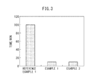
- FIG. 3 is a graph which shows the time which is required until obtaining 12 g of core-shell type metal nanoparticles of Examples 1 and 2 and Reference Example 1.
- FIG. 4 shows (a) a scan transmission type electron microscope (STEM) image of Te—Bi core-shell type metal nanoparticles which are produced according to Example 1 of the present invention and (b) a graph which shows the results of analysis by energy dispersive X-ray spectrometry (EDX).
- STEM scan transmission type electron microscope
- FIG. 5 shows (a) a scan transmission type electron microscope (STEM) image of Be—Te core-shell type metal nanoparticles produced according to Example 2 of the present invention and (b) a graph which shows the results of analysis by energy dispersive X-ray spectrometry (EDX).
- STEM scan transmission type electron microscope
- FIG. 6 is a graph which shows the concentration (ppm) of Na as an impurity element which is contained in the composite metal nanoparticles of Te and Bi and in their alloy particles of the comparative example.
- FIG. 7 is a transmission type electron microscope (TEM) image of Au—Cu core-shell type metal nanoparticles which are produced according to Reference Example 2.
- FIG. 8 is a transmission type electron microscope (TEM) image of Au—Co core-shell type metal nanoparticles which are produced according to Reference Example 3.
- each of the core-shell type metal nanoparticles has a core and at least a single layer shell which covers the core.
- the core can include at least a first metal and the shell can include at least a second metal.
- the method of the present invention for producing core-shell type metal nanoparticles is a method of production of core-shell type metal nanoparticles comprising (a) the step of introducing a solution of a salt of a first metal into a first flow path of a flow type reaction apparatus and applying plasma to the solution of the salt of the first metal in a first flow path to obtain a solution which contains metal nanoparticles of the first metal and (b) the step of introducing a solution of a salt of the second metal into a second flow path of a flow type reaction apparatus and making it merge with the solution containing metal nanoparticles of the first metal to obtain a mixed solution and applying plasma to the mixed solution to cover the metal nanoparticles of the first metal by the second metal.
- the solution plasma method in general is the method of generating plasma in a solution which contains metal ions so as to utilize the reducing action of plasma to reduce the metal ions and make the metal nanoparticles precipitate.
- the only reaction site in the solution plasma method is between the electrodes where the plasma is generated.
- the reaction site is small, so in general the solution plasma method is considered to be poor.
- the method of the present invention utilizes a flow type reaction apparatus and solution plasma method to continuously apply plasma to a starting solution to continuously produce core-shell type metal nanoparticles. Further, it may be considered to arrange the flow type reaction apparatuses of the present invention in parallel to enable a larger scale of operation.
- the method of the present invention is more excellent in productivity compared with the solution plasma method which used the batch system to produce core-shell type metal nanoparticles.
- the solution plasma method causes precipitation of a metal higher in oxidation reduction potential in accordance with the power of the plasma applied, that is, an easily reducing metal, with priority. For this reason, for example, if using a solution containing two or more types of metal ions and a high power plasma for causing precipitation of the metal with a lower oxidation reduction potential, that is, a not easily reducing metal, the easily reducing metal also precipitates. Therefore, if using the conventional batch type solution plasma method, making the not easily reducing metal the core and making the easily reducing metal the shell would usually be hard to believe.
- the inventors discovered that when sintering composite metal nanoparticles to obtain an alloy material, for example, a thermoelectric conversion material, sometimes the more easily vaporizing metal vaporizes away relatively more and the desired alloy composition cannot be obtained.
- an alloy material for example, a thermoelectric conversion material
- thermoelectric conversion material when sintering composite metal nanoparticles including Bi and Te to obtain a thermoelectric conversion material, sometimes the more easily vaporizing Te vaporizes away relatively more and the desired alloy composition, for example Bi 2 Te 3 , cannot be obtained.
- thermoelectric conversion material when sintering composite metal nanoparticles which include Bi and Te to obtain a thermoelectric conversion material, it may be considered to add a larger amount of Te anticipating the amount of loss of the more easily vaporizing Te, but, for example, Te is expensive, so a drop in yield should be avoided. Further, even if a drop in yield were allowed, the amount of vaporization of Te would not be constant and the desired alloy composition, for example, Bi 2 Te 3 , could not be easily obtained.
- the method of the present invention regardless of the ease of reduction of the metal, it is possible to make the easily reducing metal the core and make the not easily reducing metal the shell, so it is possible to suppress loss of the easily vaporizing metal at the time of sintering, the yield is good, and the desired alloy composition can be stably obtained.
- thermoelectric conversion material when sintering the composite metal nanoparticles containing Bi and Te to obtain a thermoelectric conversion material, it is possible to make the easily reducing Te the core and make the not easily reducing Bi the shell. Therefore, it is possible to cover the easily vaporizing Te by the not easily vaporizing Bi at the time of sintering so as to suppress the loss of the easily vaporizing Te at the time of sintering, so it is possible to obtain the desired alloy composition, for example, Bi 2 Te 3 , stably with a good yield.
- a lower melting point metal melts earlier than a higher melting point metal to first flow into fine shaped parts, for example, clearances between the die and cover, and the desired alloy composition and/or uniform alloy composition cannot be obtained.
- the inventors discovered that, for example, when heating while sealed or heating while sealed and under pressure to sinter nanoparticles containing for example Bi and Te and obtain any shape of thermoelectric conversion material, the lower melting point Bi melts earlier than the higher melting point Te, so the Bi first flows into fine shaped parts, for example, clearances between the die and cover, and the desired alloy composition and/or uniform alloy composition, for example, Bi 2 Te 3 , cannot be obtained.
- the method of the present invention it is possible to make the not easily reducing Bi the core and making the easily reducing Te the shell. Therefore, it is possible to cover the lower melting point Bi with the higher melting point Te and thereby cause the core Bi to melt before, then make the shell Te melt at the time of sintering, so it is possible to reduce the melt loss of Bi and possible to stably obtain a uniform alloy composition, for example, Bi 2 Te 3 .
- the method of the present invention for producing core-shell type metal nanoparticles introduces a solution of a salt of a first metal into a first flow path of the flow type reaction apparatus and applies plasma to the solution of the salt of the first metal in the first flow path to obtain a solution of metal nanoparticles of the first metal.
- the solution of the salt of the first metal includes a salt of the first metal and a solvent and is preferably substantially comprised of a salt of the first metal and a solvent.
- substantially comprised of a salt of the first metal and a solvent means that other than the salt of the first metal and solvent, no dispersant or other additive is deliberately included.
- any metal can be used.
- Al, Ge, Sn, Sb, Te, Pb, Bi, or other semimetals or non-transition metals (main group metals) and Ti, V, Cr, Mn, Fe, Co, Ni, Cu, Ag, Pt, Au, or other transition metals and combinations of the same may be mentioned.
- any metal salt can be used.
- the metal salt for example, chlorates, nitrates, phosphates, sulfates, hydrofluorides, or other inorganic acid salts, carbonates, borates, silicates, chromates, or other oxolates, stearates, laureates, ricinoleates, octylates, or other carboxylates, or ammine complexes, halogeno complexes, hydroxy complexes, or other metal complexes may be mentioned.
- the solvent is not particularly limited so long as it can dissolve the salt of the first metal.
- water or an organic solvent for example, ethanol, methanol, isopropanol, or other alcohols, heptane, hexane, nonane, and other alkanes, or benzene, toluene, xylene, or other aromatic hydrocarbons, etc. may be mentioned.
- the concentration of the salt of the first metal in the solution of a salt of the first metal can be freely set based on the power of the plasma or the particle size distribution of the desired metal nanoparticles etc.
- any method may be used. For example, pumping or transport by a cylinder etc. may be mentioned.
- the flow rate (ml/min) of the solution of the salt of the first metal may be freely set based on the cross-sectional area of the first flow path or the power of the plasma applied etc. so as to obtain the particle size, particle size distribution, productivity, etc. of the desired metal nanoparticles.
- the method for applying plasma to the solution of the salt of the first metal inside the first flow path for example, it is possible to apply voltage to at least one electrode pair which is provided at the first flow path to generate plasma between electrodes while running the first salt solution between the electrodes.
- the waveform of the voltage to be applied is not particularly limited.
- a DC voltage, AC voltage, pulse voltage, etc. may be mentioned.
- the lower limit of the voltage which is applied is not particularly limited so long as it is possible to generate plasma between the electrodes. It differs depending on the particle size etc. of the desired metal nanoparticles. For example, it may be made 0.5 kV or more, preferably 1.0 kV or more.
- the upper limit of the voltage which is applied can be freely set. For example, it may be made 100 kV or less, preferably 2.0 kV or less.
- the lower limit of the power which is applied can be freely set based on the oxidation reduction potential of the metal which is selected. It is not particularly limited so long as the selected metal can be made to precipitate.
- the “oxidation reduction potential” means the electrode potential (V) which is determined relative to standard hydrogen electrodes.
- the oxidation reduction potential of Bi 3+ is about 0.3172V, so the lower limit of the power which is applied, for example, can be made 100 W or more, preferably 140 W or more.
- the oxidation reduction potential of Te 4+ is about 0.5213V, so the lower limit of the power which is applied, for example, is made 30 W or more, preferably 50 W or more.
- the upper limit of the power which is applied can be freely set by the particle size etc. of the desired metal nanoparticles. For example, it is made 10 kW or less, preferably 500 W or less.
- the particle size of the metal nanoparticles of the first metal can be made any particle size corresponding to the application of the core-shell type metal nanoparticles.
- the lower limit of the particle size can be made, for example, 0.1 nm or more, preferably 10 nm or more, while the upper limit of the particle size can be made 500 nm or less, preferably 30 nm or less.
- the particle size can be found by observing a sample by a scan type electron microscope (SEM), transmission type electron microscope (TEM), etc., taking a photograph, directly measuring the circle equivalent particle size of the projected area based on the obtained image, and analyzing groups of particles comprised of several hundred particles or more so as to find the number average primary particle size.
- SEM scan type electron microscope
- TEM transmission type electron microscope
- the method of the present invention for producing core-shell type metal nanoparticles includes the process of introducing a solution of a salt of a second metal to a second flow path of the flow type reaction apparatus, making it merge with a solution containing metal nanoparticles of the first metal to obtain a mixed solution, and applying plasma to the mixed solution to cover the metal nanoparticles of the first metal by the second metal.
- the solution of the salt of the second metal includes a salt of a second metal and a solvent, preferably is substantially comprised of a salt of a second metal and a solvent.
- substantially comprised of a salt of the second metal and a solvent means that other than the salt of the second metal and solvent, no dispersant or other additive is deliberately included.
- the second metal, the salt of the second metal, the solvent, and the concentration of the salt of the second metal in the solution of a salt of the second metal can be made ones similar to the explanation of the first metal.
- the introduction of the solution of the salt of the second metal to the second flow path and the flow rate can be made ones similar to the explanation of the solution of the salt of the first metal.
- the first flow path and the second flow path can be merged in any way so long as mixing the solution containing nanoparticles of the first metal and the solution of the salt of the second metal so as to form a mixed solution.
- mixing it is also possible to use a mixing device for promoting mixing.
- the flow path through which the mixed solution flows after the first flow path and the second flow path are made to merge will for convenience bee referred to as the “third flow path”.
- the method of applying plasma to a mixed solution for example, it is possible to apply voltage to the at least one electrode pair which is provided in the third flow path so as to cause plasma to be generated between the electrodes while running a mixed solution between the electrodes.
- the voltage and power of the plasma at the process (b) can be made ones similar to the explanation in the process (a).
- the particle size of the core-shell type metal nanoparticles can be made any particle size in accordance with the application.
- the lower limit of the particle size can be made, for example, 0.1 nm or more, preferably 20 nm or more, while the upper limit of the particle size can be made 500 nm or less, preferably 30 nm or less.
- the flow type reaction apparatus of the present invention has a first flow path, a second flow path, and a third flow path comprised of the first flow path and the second flow path merged together. Further, the first flow path has at least one electrode pair which generates plasma, and the third flow path has at least one electrode pair which generates plasma.
- the “flow type reaction apparatus” generally means an apparatus which can continuously run a starting solution through the inside of a flow path, which can perform reactions and various operations such as mixing inside the flow path, and which can continuously produce a product.
- the size of the flow type reaction apparatus is not particularly limited.
- the upper limit of the equivalent diameter of the flow path for example, 10 mm or less, preferably 3 mm or less, may be mentioned.
- the upper limit of the equivalent diameter of the flow path at the part where plasma is applied is for example 10 mm or less, preferably 1 mm or less, it is possible to apply plasma more uniformly to the running solution.
- the lower limit of the equivalent diameter of the flow path for example, 1 ⁇ m or more, preferably 100 ⁇ m or more is mentioned.
- the flow type reaction apparatus is not particularly limited.
- a microreactor for example, one called a “microreactor” may be mentioned.
- the electrode pairs it is possible to use any electrodes so long as application of voltage enables generation of plasma.
- the material of the electrode pairs for example, tungsten, copper, chromium, graphite, etc. may be mentioned.
- the core-shell type metal nanoparticles of the present invention are core-shell type metal nanoparticles which are obtained by a method including (a) a step of introducing a solution of a salt of a first metal to a first flow path of a flow type reaction apparatus and applying plasma to the solution of the salt of the first metal in the first flow path to obtain a solution which contains metal nanoparticles of the first metal and (b) a step of introducing a solution of a salt of a second metal to a second flow path of the flow type reaction apparatus, making it merge with the solution which contains metal nanoparticles of the first metal to obtain a mixed solution, and applying plasma to the mixed solution to cover the metal nanoparticles of the first metal by the second metal.
- the core-shell type metal nanoparticles of the present invention it is possible to produce extremely high purity products, for example, catalysts or thermoelectric conversion materials etc., so it is possible to obtain products which have high characteristics, for example, high catalyst functions or high thermoelectric conversion characteristics.
- the “impurity elements which are contained in the core-shell type metal nanoparticles” indicate elements which are not deliberately included in the composition of the core-shell type metal nanoparticles. Therefore, the elements due to the additives which are deliberately included in the final core-shell type metal nanoparticles are not deemed impurity elements.
- the impurity elements are not particularly limited.
- alkali metals, alkali earth metals, transition metals, or other metals, boron, aluminum, silicon, or other base metals or semimetals, carbon, nitrogen, phosphorus, sulfur, or other nonmetals due to the reducing agent and/or dispersant may be mentioned.
- the alloy particles of the present invention are alloy particles which are obtained by alloying the core-shell type metal nanoparticles of the present invention.
- alloy particles of the present invention it is possible to produce extremely high purity products, for example, catalysts or thermoelectric conversion materials etc., so it is possible to obtain products which have high characteristics, for example, high catalyst functions or high thermoelectric conversion characteristics.
- the method of alloying can be performed by any method.
- hydrothermal synthesis or other heat treatment may be mentioned.
- the hydrothermal synthesis can be performed by any method. For example, it is possible to fill an autoclave or other sealed container with core-shell type nanoparticles and water and heat them while sealing the container.
- the temperature of the alloying can be freely set as long as alloying at least part of the core-shell type metal nanoparticles.
- the lower limit for example, 150° C. or more, preferably 250° C. or more
- the upper limit for example, 400° C. or less, preferably 300° C. or less
- thermoelectric conversion material of the present invention is a thermoelectric conversion material which is obtained by sintering the core-shell type metal nanoparticles of the present invention or the alloy particles of the present invention.
- thermoelectric conversion material of the present invention it is possible to greatly reduce the possibility of the thermoelectric conversion characteristic being damaged due to impurity elements which had been considered sufficiently removed in the past, so a high thermoelectric conversion performance can be obtained.
- the method of bonding may be any method.
- the temperature of the sintering can be freely set so long as a temperature which enables the particles to be bonded with each other and which allows for scattering of the component elements.
- the lower limit of the temperature of sintering can, for example, be made 300° C. or more, preferably 400° C. or more, while the upper limit can be made 550° C. or less, preferably 450° C. or less.
- the sintering can be performed in the air and can optionally be performed in nitrogen or argon or another inert gas.
- Te—Bi core-shell type metal nanoparticles having Te as cores and having Bi as shells were prepared. These were alloyed to prepare Bi 2 Te 3 alloy particles. Further, the Bi 2 Te 3 alloy particles were sintered to prepare a Bi 2 Te 3 thermoelectric conversion material.
- FIG. 1 is a schematic view which shows an illustrative embodiment of the method of the present invention for producing core-shell type metal nanoparticles and a flow type reaction apparatus of the present invention.
- the first metal salt solution ( 20 ) a solution of 100 ml of an ethanol solvent in which 0.214 g of TeCl 4 is contained was used.
- the second metal salt solution ( 30 ) a solution of 100 ml of an ethanol solvent in which 0.170 g of BiCl 3 is contained was used.
- the first metal salt solution ( 20 ) is introduced using the pump (P 1 ) to the first flow path ( 11 ) of the flow type reaction apparatus ( 10 ) at 10 ml/min.
- the second metal salt solution ( 30 ) was introduced using the pump (P 2 ) to the second flow path ( 12 ) of the flow type reaction apparatus ( 10 ) at 10 ml/min and made to merge with the solution containing the Te metal nanoparticles to obtain a mixed solution.
- the flow rate of the mixed solution at the third flow path ( 13 ) was 20 ml/min.
- Te—Bi core-shell type metal nanoparticles which were then washed by ethanol, washed by water, again washed by ethanol, and further dried to thereby prepare Te—Bi core-shell type metal nanoparticles in about 12 g.
- Te—Bi type metal nanoparticles were alloyed at 270° C. for 10 hours by hydrothermal synthesis to obtain an aqueous solution which contains Bi 2 Te 3 alloy particles.
- the obtained aqueous solution was filtered to take out Bi 2 Te 3 alloy particles which were then washed by ethanol, washed by water, again washed by ethanol, and further dried to thereby prepare Bi 2 Te 3 alloy particles.
- Example 2 as the solution of the salt of the first metal ( 20 ), a solution comprising 100 ml of ethanol solvent in which 0.170 g of BiCl 3 is included was used. As the salt solution ( 30 ) of the second metal, a solution comprised of 100 ml of ethanol solvent in which 0.214 g of TeCl 4 is contained was used.
- Example 2 except for making the power of the plasma in procedure (a) 140 W and making the power of the plasma in procedure (b) 50 W the same procedure was followed as in Example 1 to prepare Bi—Te core-shell type metal nanoparticles in an amount of about 12 g.
- a batch type reaction apparatus ( 50 ) was filled with the starting solution ( 51 ) which was stirred by a stirrer ( 53 ) while applying 1.5 kV of voltage to a tungsten electrode pair ( 52 ) by 50 W power to cause the generation of plasma between electrodes and thereby apply plasma to the starting solution ( 51 ). Due to this, the more easily reducing Te first started to precipitate.
- UV-vis visible ultraviolet spectrophotometer
- Te—Bi core-shell type metal nanoparticles which were then washed by ethanol, washed by water, again washed by ethanol, and further dried to thereby prepare Te—Bi core-shell type metal nanoparticles in an amount of about 12 g.
- a reducing agent constituted by NaBH 4 was used to prepare Bi and Te composite metal nanoparticles, these were alloyed to prepare Bi 2 Te 3 alloy particles, and, further, these were sintered to prepare a Bi 2 Te 3 thermoelectric conversion material.
- a solution comprising 100 ml of ethanol in which 0.170 g of BiCl 3 and 0.214 g of TeCl 4 were contained was used.
- a reducing agent solution comprised of 100 ml of ethanol in which 0.218 g of NaBH 4 was contained was used.
- the container was charged with the starting solution which was stirred while adding a reducing agent solution containing NaBH 4 to cause Bi and Te composite metal nanoparticles to precipitate.
- the obtained solution was filtered to take out Bi and Te composite metal nanoparticles which were then washed by ethanol, washed by water, again washed by ethanol, and furthermore dried to prepare Bi and Te composite metal nanoparticles.
- the obtained Bi and Te composite metal nanoparticles were alloyed by hydrothermal synthesis at 270° C. for 10 hours to obtain an aqueous solution which contains Bi 2 Te 3 alloy particles.
- the obtained aqueous solution was filtered to take out Bi 2 Te 3 alloy particles which were then washed by ethanol, washed by water, again washed by ethanol, and further dried to thereby prepare Bi 2 Te 3 alloy particles.
- the obtained Bi 2 Te 3 alloy particles were sintered in an Ar atmosphere at 400° C. to obtain a sintered body of a Bi 2 Te 3 thermoelectric conversion material.
- FIG. 4( a ) A STEM image of the Te—Bi core-shell type metal nanoparticles which were obtained in Example 1 is shown in FIG. 4( a ) , while the results of EDX analysis along the white line of FIG. 4( a ) are shown in FIG. 4( b ) .
- FIG. 5( a ) A STEM image of the Bi—Ti core-shell type metal nanoparticles which were obtained in Example 2 is shown in FIG. 5( a ) , while the results of EDX analysis along the white line of FIG. 5( a ) are shown in FIG. 5( b ) .
- either of Bi and Te can be made the core or can be made the shell.
- both Bi and Te end up precipitating so Bi cannot be made the core. Therefore, it will be understood that the method and apparatus of the present invention are high in degree of freedom of design of the core and shell.
- the left side of the graph of FIG. 6 from the broken line shows the concentration (ppm) of Na as an impurity element contained in the Te and Bi composite metal nanoparticles which are produced in the comparative example.
- the right side of the graph of FIG. 6 from the broken line shows the concentration (ppm) of Na as an impurity element contained in the alloy particles which are obtained by alloying the Te and Bi composite metal nanoparticles which are produced in the comparative example.
- the Te and Bi composite metal nanoparticles of the comparative example As shown in FIG. 6 , from the Te and Bi composite metal nanoparticles of the comparative example, over 300 to 4000 ppm of Na was detected as an impurity element. From these alloy particles, over 5 ppm to 200 ppm of Na was detected as an impurity element. As opposed to this, the core-shell type nanoparticles which were produced in Example 1 do not use any reducing agent, dispersant, or other additive, so no Na is detected as an impurity element.
- the batch type solution plasma method was used by the following procedure to prepare Au—Cu core-shell type nanoparticles which are useful as catalyst metal.
- a solution of 200 ml of ethanol solvent including 1.2 mmol of tetrachloroauric (III) acid (HAuCl 4 .4H 2 O), 4.8 mmol of copper acetate (II) (Cu(CH 3 COO) 2 .H 2 O), and 5 mmol of NaI was used.
- a method similar to Reference Example 1 was used to prepare Au—Cu core-shell type nanoparticles by an applied voltage of 1.5 kV while switching the power of the plasma from 50 W to 140 W.
- FIG. 7 shows a TEM image of the obtained metal nanoparticles. It is understood that Au—Cu core-shell type metal nanoparticles were formed.
- the batch type solution plasma method was used by the following procedure to prepare Au—Co core-shell type nanoparticles which are useful as catalyst metal.
- a solution of 200 ml of ethanol solvent including 1.2 mmol of tetrachloroauric (III) acid (HAuCl 4 .4H 2 O), 4.8 mmol of cobalt acetate (II) (Co(CH 3 COO) 2 .4H 2 O), and 5 mmol of NaI was used.
- a method similar to Reference Example 1 was used to prepare Au—Co core-shell type nanoparticles by an applied voltage of 1.5 kV while switching the power of the plasma from 50 W to 140 W.
- FIG. 8 shows a TEM image of the obtained metal nanoparticles. It is understood that Au—Co core-shell type metal nanoparticles were formed.
- Reference Example 1 and Example 1 both can produce Te—Bi core-shell type metal nanoparticles and from the description of Reference Example 2 by making a solvent comprised of ethanol containing tetrachloroauric (III) acid (HAuCl 4 .4H 2 O) the solution of the salt of the first metal and making a solution of ethanol containing copper acetate (II) (Cu(CH 3 COO) 2 .H 2 O) the solution of the salt of the second metal.
- a solvent comprised of ethanol containing tetrachloroauric (III) acid (HAuCl 4 .4H 2 O) the solution of the salt of the first metal and making a solution of ethanol containing copper acetate (II) (Cu(CH 3 COO) 2 .H 2 O) the solution of the salt of the second metal.
Landscapes
- Chemical & Material Sciences (AREA)
- Chemical Kinetics & Catalysis (AREA)
- Engineering & Computer Science (AREA)
- Organic Chemistry (AREA)
- Materials Engineering (AREA)
- Health & Medical Sciences (AREA)
- Toxicology (AREA)
- Physics & Mathematics (AREA)
- Inorganic Chemistry (AREA)
- General Chemical & Material Sciences (AREA)
- General Health & Medical Sciences (AREA)
- Optics & Photonics (AREA)
- Plasma & Fusion (AREA)
- Nanotechnology (AREA)
- Manufacture Of Metal Powder And Suspensions Thereof (AREA)
- Powder Metallurgy (AREA)
- Catalysts (AREA)
- Dispersion Chemistry (AREA)
Abstract
Description
- PLT 1: Japanese Patent Publication No. 2011-195420A
- PLT 2: Japanese Patent Publication No. 2008-013810 A
- PLT 3: Japanese Patent Publication No. 2013-108121 A
- PLT 4: Japanese Patent Publication No. 2008-246394 A
- PLT 5: Japanese Patent Publication No. 2005-294478 A
(b) a step of introducing a solution of a salt of a second metal to a second flow path of a flow type reaction apparatus, making it merge with the solution which contains metal nanoparticles of the first metal to obtain a mixed solution, and applying plasma to the mixed solution to cover the metal nanoparticles of the first metal by the second metal.
<2> The method according to <1> wherein an oxidation reduction potential of the first metal is lower than an oxidation reduction potential of the second metal.
<3> The method according to <1> wherein the first metal is Te and the second metal is Bi or wherein the first metal is Bi and the second metal is Te.
<4> The method according to any one of <1> to <3> wherein an equivalent diameter when converting a cross-sectional area of the flow path to a circle of the same area is 1 μm to 10 mm.
<5> A flow type reaction apparatus which has a first flow path, a second flow path, and a third flow path which is formed by the first flow path and the second flow path merged together, wherein the first flow path has at least one electrode pair which generates plasma and the third flow path has at least one electrode pair which generates plasma.
<6> The flow type reaction apparatus according to <5> wherein an equivalent diameter of the flow path at the part where the plasma is applied is 1 μm to 10 mm.
<7> Core-shell type metal nanoparticles obtained by a method including:
(a) a step of introducing a solution of a salt of a first metal to a first flow path of a flow type reaction apparatus and applying plasma to the solution of the salt of the first metal in the first flow path to obtain a solution which contains metal nanoparticles of the first metal and
(b) a step of introducing a solution of a salt of a second metal to a second flow path of a flow type reaction apparatus, making it merge with the solution which contains metal nanoparticles of the first metal to obtain a mixed solution, and applying plasma to the mixed solution to cover the metal nanoparticles of the first metal by the second metal.
<8> Alloy particles which are obtained by alloying the core-shell type metal nanoparticles according to <7>.
<9> A thermoelectric conversion material which is obtained by sintering core-shell type metal nanoparticles according to <7> or alloy particles according to <8>.
- 10 flow type reaction apparatus
- 11 first flow path
- 12 second flow path
- 13 third flow path
- 14 a, 14 b electrode pair
- 20 solution of salt of first metal
- 30 solution of salt of second metal
- 40 solution containing core-shell type metal nanoparticles
- 50 batch type reaction apparatus
- 51 starting solution
- 52 electrode pair
- 53 stirrer
Claims (2)
Applications Claiming Priority (2)
| Application Number | Priority Date | Filing Date | Title |
|---|---|---|---|
| JP2014-022237 | 2014-02-07 | ||
| JP2014022237A JP6034317B2 (en) | 2014-02-07 | 2014-02-07 | Method and apparatus for producing core-shell type metal nanoparticles |
Publications (2)
| Publication Number | Publication Date |
|---|---|
| US20150224483A1 US20150224483A1 (en) | 2015-08-13 |
| US10076745B2 true US10076745B2 (en) | 2018-09-18 |
Family
ID=52464232
Family Applications (1)
| Application Number | Title | Priority Date | Filing Date |
|---|---|---|---|
| US14/614,738 Active 2035-04-02 US10076745B2 (en) | 2014-02-07 | 2015-02-05 | Method and apparatus for producing core-shell type metal nanoparticles |
Country Status (6)
| Country | Link |
|---|---|
| US (1) | US10076745B2 (en) |
| EP (1) | EP2905095B1 (en) |
| JP (1) | JP6034317B2 (en) |
| KR (1) | KR101717834B1 (en) |
| CN (1) | CN104827048B (en) |
| TW (1) | TWI659672B (en) |
Cited By (1)
| Publication number | Priority date | Publication date | Assignee | Title |
|---|---|---|---|---|
| RU2846419C2 (en) * | 2023-12-31 | 2025-09-05 | Общество С Ограниченной Ответственностью "Новые Дисперсные Материалы" | Method of producing powder with core-shell structure |
Families Citing this family (9)
| Publication number | Priority date | Publication date | Assignee | Title |
|---|---|---|---|---|
| WO2018037419A1 (en) * | 2016-08-26 | 2018-03-01 | Ariel Scientific Innovations Ltd. | Tin-based catalysts, the preparation thereof, and fuel cells using the same |
| JP7089841B2 (en) * | 2016-09-01 | 2022-06-23 | 旭化成株式会社 | New core-shell nanoparticles and their manufacturing methods |
| CN109309155B (en) * | 2017-07-28 | 2022-04-19 | 丰田自动车株式会社 | High-manganese-silicon-based telluride thermoelectric composite material and preparation method thereof |
| CN107628591B (en) * | 2017-10-12 | 2019-07-09 | 北京科技大学 | A kind of preparation method of yolk-shell structure Co9Se8 nanoparticles |
| JP7137737B2 (en) * | 2018-09-26 | 2022-09-15 | 住友理工株式会社 | METHOD FOR MANUFACTURING METAL NANOPARTICLES |
| EP3633043A1 (en) * | 2018-10-02 | 2020-04-08 | Nanobacterie | Cellular production of pure iron oxide nanoparticles |
| KR102051321B1 (en) * | 2019-07-15 | 2019-12-03 | 파워팩 주식회사 | A method for preparing silver-copper mixture powder of core-shell structure using wet process |
| CN115815594B (en) * | 2022-12-17 | 2025-12-23 | 西安交通大学 | System and method for synthesizing silver-coated copper powder with core-shell structure |
| CN119747650A (en) * | 2024-12-23 | 2025-04-04 | 广东工业大学 | A method and device for preparing metallization paste for packaging substrate |
Citations (13)
| Publication number | Priority date | Publication date | Assignee | Title |
|---|---|---|---|---|
| US6358562B1 (en) | 1998-04-08 | 2002-03-19 | Forschungszentrum Karlsruhe Gmbh | Method for the production of coated particles |
| US20050129580A1 (en) * | 2003-02-26 | 2005-06-16 | Swinehart Philip R. | Microfluidic chemical reactor for the manufacture of chemically-produced nanoparticles |
| JP2005294478A (en) | 2004-03-31 | 2005-10-20 | Dainippon Printing Co Ltd | Thermoelectric conversion material |
| US20060060998A1 (en) * | 2004-09-20 | 2006-03-23 | The Regents Of The University Of California | Method for synthesis of colloidal nanoparticles |
| JP2008013810A (en) | 2006-07-05 | 2008-01-24 | Univ Of Tokyo | Metal nanoparticle generation method and metal nanoparticle generation apparatus |
| JP2008246394A (en) | 2007-03-30 | 2008-10-16 | 3R Corp | Nanoparticle production method and nanoparticle production apparatus |
| US20090317557A1 (en) | 2008-06-20 | 2009-12-24 | Toyota Motor Engineering & Manufacturing North America, Inc. | Process To Make Core-Shell Structured Nanoparticles |
| US20100105548A1 (en) | 2008-10-24 | 2010-04-29 | Gm Global Technology Operations, Inc. | Method for generating a shell of noble metal overlaid on a core of non-noble metal, and catalysts made thereby |
| JP2011195420A (en) | 2010-03-23 | 2011-10-06 | National Institute Of Advanced Industrial Science & Technology | Method for producing metal oxide fine particle |
| WO2012083442A1 (en) * | 2010-12-20 | 2012-06-28 | UNIVERSITé LAVAL | Radioactive and/or magnetic metal nanoparticles and process and apparatus for synthesizing same |
| WO2013039117A1 (en) | 2011-09-12 | 2013-03-21 | 独立行政法人産業技術総合研究所 | Continuous synthesis method for metal core and oxide shell core-shell structure nanoparticles, continuous synthesis apparatus for same, and core-shell structure nanoparticles |
| CN103008684A (en) | 2013-01-21 | 2013-04-03 | 北京大学 | Method for preparing metal nanoparticles by means of atmospheric pressure cold plasmas |
| JP2013108121A (en) | 2011-11-18 | 2013-06-06 | Noritake Co Ltd | Method for producing metal nanoparticle |
Family Cites Families (5)
| Publication number | Priority date | Publication date | Assignee | Title |
|---|---|---|---|---|
| US20090314324A1 (en) * | 2005-12-07 | 2009-12-24 | Junya Murai | Thermoelectric conversion material and method of producing the same |
| JP4900061B2 (en) * | 2007-06-06 | 2012-03-21 | トヨタ自動車株式会社 | Thermoelectric conversion element and manufacturing method thereof |
| KR20110028632A (en) * | 2008-06-23 | 2011-03-21 | 이섬 리서치 디벨러프먼트 컴파니 오브 더 히브루 유니버시티 오브 예루살렘 엘티디. | Core-Shell Metal Nanoparticles, Methods for Making the Same, and Ink Compositions Containing the Same |
| GB201213624D0 (en) * | 2012-07-27 | 2012-09-12 | Univ Ulster The | Method and system for production of conjugated nanoparticles |
| JP6001578B2 (en) * | 2014-01-31 | 2016-10-05 | トヨタ自動車株式会社 | Method for producing core / shell type nanoparticles and method for producing sintered body using the method |
-
2014
- 2014-02-07 JP JP2014022237A patent/JP6034317B2/en not_active Expired - Fee Related
-
2015
- 2015-02-04 KR KR1020150017275A patent/KR101717834B1/en not_active Expired - Fee Related
- 2015-02-05 US US14/614,738 patent/US10076745B2/en active Active
- 2015-02-06 EP EP15154141.4A patent/EP2905095B1/en not_active Not-in-force
- 2015-02-06 CN CN201510063447.8A patent/CN104827048B/en not_active Expired - Fee Related
- 2015-02-06 TW TW104104064A patent/TWI659672B/en not_active IP Right Cessation
Patent Citations (17)
| Publication number | Priority date | Publication date | Assignee | Title |
|---|---|---|---|---|
| US6358562B1 (en) | 1998-04-08 | 2002-03-19 | Forschungszentrum Karlsruhe Gmbh | Method for the production of coated particles |
| US20050129580A1 (en) * | 2003-02-26 | 2005-06-16 | Swinehart Philip R. | Microfluidic chemical reactor for the manufacture of chemically-produced nanoparticles |
| JP2005294478A (en) | 2004-03-31 | 2005-10-20 | Dainippon Printing Co Ltd | Thermoelectric conversion material |
| US20050268956A1 (en) | 2004-03-31 | 2005-12-08 | Seiji Take | Thermoelectric conversion materials |
| US7259320B2 (en) * | 2004-03-31 | 2007-08-21 | Dai Nippon Printing Co., Ltd. | Thermoelectric conversion materials |
| US20060060998A1 (en) * | 2004-09-20 | 2006-03-23 | The Regents Of The University Of California | Method for synthesis of colloidal nanoparticles |
| JP2008013810A (en) | 2006-07-05 | 2008-01-24 | Univ Of Tokyo | Metal nanoparticle generation method and metal nanoparticle generation apparatus |
| JP2008246394A (en) | 2007-03-30 | 2008-10-16 | 3R Corp | Nanoparticle production method and nanoparticle production apparatus |
| US20090317557A1 (en) | 2008-06-20 | 2009-12-24 | Toyota Motor Engineering & Manufacturing North America, Inc. | Process To Make Core-Shell Structured Nanoparticles |
| US20100105548A1 (en) | 2008-10-24 | 2010-04-29 | Gm Global Technology Operations, Inc. | Method for generating a shell of noble metal overlaid on a core of non-noble metal, and catalysts made thereby |
| DE102009050120A1 (en) | 2008-10-24 | 2010-05-12 | GM Global Technology Operations, Inc., Detroit | A method of producing a noble metal shell on a non-noble metal core and catalysts made therefrom |
| JP2011195420A (en) | 2010-03-23 | 2011-10-06 | National Institute Of Advanced Industrial Science & Technology | Method for producing metal oxide fine particle |
| WO2012083442A1 (en) * | 2010-12-20 | 2012-06-28 | UNIVERSITé LAVAL | Radioactive and/or magnetic metal nanoparticles and process and apparatus for synthesizing same |
| US20140227176A1 (en) * | 2010-12-20 | 2014-08-14 | Universite Laval | Radioactive and/or Magnetic Metal Nanoparticles and Process and Apparatus for Synthesizing Same |
| WO2013039117A1 (en) | 2011-09-12 | 2013-03-21 | 独立行政法人産業技術総合研究所 | Continuous synthesis method for metal core and oxide shell core-shell structure nanoparticles, continuous synthesis apparatus for same, and core-shell structure nanoparticles |
| JP2013108121A (en) | 2011-11-18 | 2013-06-06 | Noritake Co Ltd | Method for producing metal nanoparticle |
| CN103008684A (en) | 2013-01-21 | 2013-04-03 | 北京大学 | Method for preparing metal nanoparticles by means of atmospheric pressure cold plasmas |
Non-Patent Citations (6)
| Title |
|---|
| "Reduction of Lattice Thermal Conductivity in Single Bi-Te Core/Shell Nanowires with Rough Interface", Joohoon Kang , Jong Wook Roh , Wooyoung Shim , Jinhee Ham , Jin-Seo Noh, and Wooyoung Lee, Adv. Mater. 2011, 23, 3414-3419. * |
| "Synthesis and characteristics of Ag/Pt bimetallic nanocomposites by arc-discharge solution plasma processing", Panuphong Pootawang, Nagahiro Saito, Osamu Takai and Sang-Yul Lee, Nanotechnology 23 (2012) 395602 (8pp). * |
| "Reduction of Lattice Thermal Conductivity in Single Bi—Te Core/Shell Nanowires with Rough Interface", Joohoon Kang , Jong Wook Roh , Wooyoung Shim , Jinhee Ham , Jin-Seo Noh, and Wooyoung Lee, Adv. Mater. 2011, 23, 3414-3419. * |
| Junko Hieda, et al., "Solution Plasma Surface Modification for Nanocarbon-Composite Materials", The Japan Institute of Metals, 2009, pp. 938-942, vol. 73, No. 12. |
| Kim et al., "Bismuth-telluride Thermoelectric Nanoparticles Synthesized by Using a Polyol Process", Journal of the Korean Physical Society, Oct. 2010, vol. 57, No. 4, pp. 1037-1040. |
| Panuphong Pootawang, et al., "Ag nanoparticle incorporation in mesoporous silica synthesized by solution plasma and their catalysis for oleic acid hydrogenation", Materials Letters, Jan. 2011, pp. 1037-1040, vol. 65. |
Cited By (2)
| Publication number | Priority date | Publication date | Assignee | Title |
|---|---|---|---|---|
| RU2846419C2 (en) * | 2023-12-31 | 2025-09-05 | Общество С Ограниченной Ответственностью "Новые Дисперсные Материалы" | Method of producing powder with core-shell structure |
| RU2846622C2 (en) * | 2023-12-31 | 2025-09-10 | Общество С Ограниченной Ответственностью "Новые Дисперсные Материалы" | Apparatus for producing powder with core-shell structure |
Also Published As
| Publication number | Publication date |
|---|---|
| EP2905095A1 (en) | 2015-08-12 |
| TWI659672B (en) | 2019-05-11 |
| EP2905095B1 (en) | 2017-01-25 |
| KR20150093597A (en) | 2015-08-18 |
| CN104827048A (en) | 2015-08-12 |
| US20150224483A1 (en) | 2015-08-13 |
| KR101717834B1 (en) | 2017-03-17 |
| CN104827048B (en) | 2018-08-17 |
| JP2015147986A (en) | 2015-08-20 |
| TW201542038A (en) | 2015-11-01 |
| JP6034317B2 (en) | 2016-11-30 |
Similar Documents
| Publication | Publication Date | Title |
|---|---|---|
| US10076745B2 (en) | Method and apparatus for producing core-shell type metal nanoparticles | |
| Sun et al. | Synthesis of metallic high-entropy alloy nanoparticles | |
| Amendola et al. | Room‐temperature laser synthesis in liquid of oxide, metal‐oxide core‐shells, and doped oxide nanoparticles | |
| Al Zoubi et al. | Experimental and theoretical investigation of high-entropy-alloy/support as a catalyst for reduction reactions | |
| Wu et al. | High‐entropy materials in electrocatalysis: understanding, design, and development | |
| Yu et al. | Far-from-equilibrium processing opens kinetic paths for engineering novel materials by breaking thermodynamic limits | |
| Zhang et al. | Formation Mechanism of Laser‐Synthesized Iron–Manganese Alloy Nanoparticles, Manganese Oxide Nanosheets and Nanofibers | |
| US12037662B2 (en) | General synthetic strategy for fabrication of multi-metallic nanostructures | |
| Wang et al. | Recent progress in high‐entropy alloy electrocatalysts for hydrogen evolution reaction | |
| Carenco et al. | Magnetic core− shell nanoparticles from nanoscale-induced phase segregation | |
| Mintcheva et al. | Nanomaterials produced by laser beam ablating Sn-Zn alloy in water | |
| Kalidindi et al. | Synthesis of Cu@ ZnO core− shell nanocomposite through digestive ripening of Cu and Zn nanoparticles | |
| US20160318099A1 (en) | Method of manufacturing metal composite powder by wire explosion in liquid and multi carbon layer coated metal composite powder | |
| JP5369576B2 (en) | Metal nanoparticle, method for producing the same, and metal nanoparticle production apparatus | |
| Rawat et al. | Laser generation of AlCrCuFeNi high-entropy alloy nanocolloids | |
| Carenco et al. | Towards nanoscaled gold phosphides: surface passivation and growth of composite nanostructures | |
| CN103476524B (en) | Manufacture the method for the metal nanoparticle with nucleocapsid structure with oxidative stability | |
| Fujita | High-entropy alloy catalysts toward multi-functionality: Synthesis, application, and material discovery | |
| Ali et al. | Probing the Dynamics Process of High‐Entropy Alloy Catalysts: Fundamentals, Synthesis, and In Situ TEM Insights | |
| Watanabe et al. | Fabrication of FeCoNi medium-entropy alloy nanoparticles by high-repetition-rate UV picosecond laser ablation in water | |
| Betancourt et al. | Synthesis and characterization of MoSe 2 nanoscrolls via pulsed laser ablation in deep eutectic solvents | |
| Kobayashi et al. | Core–Shell Multicomponent Alloys with High Specific Surface Areas Prepared by Molten Salt Synthesis for Catalytic Hydrogenation of p-Nitrophenol by NaBH4 | |
| Kang et al. | Observing the evolution of metal oxides in liquids | |
| Křenek et al. | A novel route of colloidal chemistry: room temperature reactive interactions between titanium monoxide and silicon monoxide sols produced by laser ablation in liquid resulting in the formation of titanium disilicide | |
| WO2024225447A1 (en) | Production method for recycled aluminum metal lump |
Legal Events
| Date | Code | Title | Description |
|---|---|---|---|
| AS | Assignment |
Owner name: TOYOTA JIDOSHA KABUSHIKI KAISHA, JAPAN Free format text: ASSIGNMENT OF ASSIGNORS INTEREST;ASSIGNORS:WATANABE, MASAO;ISHIKIRIYAMA, MAMORU;KINOSHITA, YOUHEI;AND OTHERS;REEL/FRAME:034897/0644 Effective date: 20150126 Owner name: NATIONAL UNIVERSITY CORPORATION NAGOYA UNIVERSITY, Free format text: ASSIGNMENT OF ASSIGNORS INTEREST;ASSIGNORS:WATANABE, MASAO;ISHIKIRIYAMA, MAMORU;KINOSHITA, YOUHEI;AND OTHERS;REEL/FRAME:034897/0644 Effective date: 20150126 |
|
| STCF | Information on status: patent grant |
Free format text: PATENTED CASE |
|
| MAFP | Maintenance fee payment |
Free format text: PAYMENT OF MAINTENANCE FEE, 4TH YEAR, LARGE ENTITY (ORIGINAL EVENT CODE: M1551); ENTITY STATUS OF PATENT OWNER: LARGE ENTITY Year of fee payment: 4 |