US10073473B2 - Indoor digital centralized controller system, air conditioning system comprising the same, and heating/cooling device comprising the same - Google Patents
Indoor digital centralized controller system, air conditioning system comprising the same, and heating/cooling device comprising the same Download PDFInfo
- Publication number
- US10073473B2 US10073473B2 US15/619,564 US201715619564A US10073473B2 US 10073473 B2 US10073473 B2 US 10073473B2 US 201715619564 A US201715619564 A US 201715619564A US 10073473 B2 US10073473 B2 US 10073473B2
- Authority
- US
- United States
- Prior art keywords
- motor
- control
- indoor
- mcu
- unit
- Prior art date
- Legal status (The legal status is an assumption and is not a legal conclusion. Google has not performed a legal analysis and makes no representation as to the accuracy of the status listed.)
- Active
Links
Images


Classifications
-
- G—PHYSICS
- G05—CONTROLLING; REGULATING
- G05D—SYSTEMS FOR CONTROLLING OR REGULATING NON-ELECTRIC VARIABLES
- G05D23/00—Control of temperature
- G05D23/19—Control of temperature characterised by the use of electric means
- G05D23/1917—Control of temperature characterised by the use of electric means using digital means
-
- F—MECHANICAL ENGINEERING; LIGHTING; HEATING; WEAPONS; BLASTING
- F24—HEATING; RANGES; VENTILATING
- F24F—AIR-CONDITIONING; AIR-HUMIDIFICATION; VENTILATION; USE OF AIR CURRENTS FOR SCREENING
- F24F11/00—Control or safety arrangements
-
- F—MECHANICAL ENGINEERING; LIGHTING; HEATING; WEAPONS; BLASTING
- F24—HEATING; RANGES; VENTILATING
- F24F—AIR-CONDITIONING; AIR-HUMIDIFICATION; VENTILATION; USE OF AIR CURRENTS FOR SCREENING
- F24F11/00—Control or safety arrangements
- F24F11/30—Control or safety arrangements for purposes related to the operation of the system, e.g. for safety or monitoring
-
- F—MECHANICAL ENGINEERING; LIGHTING; HEATING; WEAPONS; BLASTING
- F24—HEATING; RANGES; VENTILATING
- F24F—AIR-CONDITIONING; AIR-HUMIDIFICATION; VENTILATION; USE OF AIR CURRENTS FOR SCREENING
- F24F11/00—Control or safety arrangements
- F24F11/62—Control or safety arrangements characterised by the type of control or by internal processing, e.g. using fuzzy logic, adaptive control or estimation of values
-
- F—MECHANICAL ENGINEERING; LIGHTING; HEATING; WEAPONS; BLASTING
- F24—HEATING; RANGES; VENTILATING
- F24F—AIR-CONDITIONING; AIR-HUMIDIFICATION; VENTILATION; USE OF AIR CURRENTS FOR SCREENING
- F24F11/00—Control or safety arrangements
- F24F11/70—Control systems characterised by their outputs; Constructional details thereof
- F24F11/80—Control systems characterised by their outputs; Constructional details thereof for controlling the temperature of the supplied air
- F24F11/86—Control systems characterised by their outputs; Constructional details thereof for controlling the temperature of the supplied air by controlling compressors within refrigeration or heat pump circuits
-
- F—MECHANICAL ENGINEERING; LIGHTING; HEATING; WEAPONS; BLASTING
- F24—HEATING; RANGES; VENTILATING
- F24F—AIR-CONDITIONING; AIR-HUMIDIFICATION; VENTILATION; USE OF AIR CURRENTS FOR SCREENING
- F24F11/00—Control or safety arrangements
- F24F11/70—Control systems characterised by their outputs; Constructional details thereof
- F24F11/80—Control systems characterised by their outputs; Constructional details thereof for controlling the temperature of the supplied air
- F24F11/87—Control systems characterised by their outputs; Constructional details thereof for controlling the temperature of the supplied air by controlling absorption or discharge of heat in outdoor units
- F24F11/871—Control systems characterised by their outputs; Constructional details thereof for controlling the temperature of the supplied air by controlling absorption or discharge of heat in outdoor units by controlling outdoor fans
-
- F—MECHANICAL ENGINEERING; LIGHTING; HEATING; WEAPONS; BLASTING
- F24—HEATING; RANGES; VENTILATING
- F24F—AIR-CONDITIONING; AIR-HUMIDIFICATION; VENTILATION; USE OF AIR CURRENTS FOR SCREENING
- F24F11/00—Control or safety arrangements
- F24F11/88—Electrical aspects, e.g. circuits
-
- G—PHYSICS
- G05—CONTROLLING; REGULATING
- G05D—SYSTEMS FOR CONTROLLING OR REGULATING NON-ELECTRIC VARIABLES
- G05D23/00—Control of temperature
- G05D23/19—Control of temperature characterised by the use of electric means
- G05D23/1919—Control of temperature characterised by the use of electric means characterised by the type of controller
-
- F—MECHANICAL ENGINEERING; LIGHTING; HEATING; WEAPONS; BLASTING
- F24—HEATING; RANGES; VENTILATING
- F24F—AIR-CONDITIONING; AIR-HUMIDIFICATION; VENTILATION; USE OF AIR CURRENTS FOR SCREENING
- F24F11/00—Control or safety arrangements
- F24F11/30—Control or safety arrangements for purposes related to the operation of the system, e.g. for safety or monitoring
- F24F11/41—Defrosting; Preventing freezing
-
- F—MECHANICAL ENGINEERING; LIGHTING; HEATING; WEAPONS; BLASTING
- F24—HEATING; RANGES; VENTILATING
- F24F—AIR-CONDITIONING; AIR-HUMIDIFICATION; VENTILATION; USE OF AIR CURRENTS FOR SCREENING
- F24F11/00—Control or safety arrangements
- F24F11/50—Control or safety arrangements characterised by user interfaces or communication
- F24F11/54—Control or safety arrangements characterised by user interfaces or communication using one central controller connected to several sub-controllers
-
- F—MECHANICAL ENGINEERING; LIGHTING; HEATING; WEAPONS; BLASTING
- F24—HEATING; RANGES; VENTILATING
- F24F—AIR-CONDITIONING; AIR-HUMIDIFICATION; VENTILATION; USE OF AIR CURRENTS FOR SCREENING
- F24F11/00—Control or safety arrangements
- F24F11/62—Control or safety arrangements characterised by the type of control or by internal processing, e.g. using fuzzy logic, adaptive control or estimation of values
- F24F11/63—Electronic processing
-
- F—MECHANICAL ENGINEERING; LIGHTING; HEATING; WEAPONS; BLASTING
- F24—HEATING; RANGES; VENTILATING
- F24F—AIR-CONDITIONING; AIR-HUMIDIFICATION; VENTILATION; USE OF AIR CURRENTS FOR SCREENING
- F24F2110/00—Control inputs relating to air properties
- F24F2110/10—Temperature
-
- F—MECHANICAL ENGINEERING; LIGHTING; HEATING; WEAPONS; BLASTING
- F24—HEATING; RANGES; VENTILATING
- F24F—AIR-CONDITIONING; AIR-HUMIDIFICATION; VENTILATION; USE OF AIR CURRENTS FOR SCREENING
- F24F2110/00—Control inputs relating to air properties
- F24F2110/10—Temperature
- F24F2110/12—Temperature of the outside air
-
- F—MECHANICAL ENGINEERING; LIGHTING; HEATING; WEAPONS; BLASTING
- F24—HEATING; RANGES; VENTILATING
- F24F—AIR-CONDITIONING; AIR-HUMIDIFICATION; VENTILATION; USE OF AIR CURRENTS FOR SCREENING
- F24F2110/00—Control inputs relating to air properties
- F24F2110/20—Humidity
Definitions
- the invention relates to an indoor digital centralized controller system, air conditioning systems comprising the same, and a heating/cooling device comprising the same.
- ECM electronically commutated motor
- an indoor digital centralized controller system which controls multiple motors without using a motor controller.
- the indoor digital centralized controller system overlapped circuits are deleted, thus simplifying the circuit structure, lowering production cost, and reducing waste of resources.
- the indoor digital centralized controller system is well-matched with the application system, and is convenient for use.
- an indoor digital centralized controller system being connected to a controller of an application system.
- the indoor digital centralized controller system is configured to accept orders from the controller of the application system and control at least one motor to work.
- the indoor digital centralized controller system comprises a power supply, a master control unit (MCU), a plurality of motor control modules, a programming port module, and an input interface.
- the power supply is configured to supply power for circuits.
- the MCU is connected to and communicates with the controller of the application system via the input interface.
- An outer computer is capable of rewriting control programs of the MCU via the programming port module.
- the MCU is connected to a motor via a motor control module.
- the motor comprises a stator assembly, a rotor assembly, and a shell assembly.
- the stator assembly and the rotor assembly are coupled magnetically.
- the stator assembly comprises a stator core and a coil winding wound around the stator core.
- the coil winding is configured to acquire alternating current from the motor control module and generate rotating magnetic field to drive a rotor to rotate.
- the motor control module is a control module of AC motor or a control module of brushless DC motor.
- the control module of AC motor comprises a relay and a drive circuit.
- the control module of brushless DC motor comprises a detecting unit of rotor position, a microprocessor, and an inverter unit.
- the detecting unit of rotor position is configured to transmit rotor position data of a permanent magnet motor to the microprocessor.
- the microprocessor is configured to control the inverter unit to output alternating current to the coil winding on the stator core.
- the microprocessor is connected to and communicates with the MCU.
- the motor control module is a control module of AC motor or a control module of brushless DC motor.
- the control module of AC motor comprises a relay and a drive circuit.
- the control module of brushless DC motor comprises a detecting unit of phase current, a microprocessor, and an inverter unit.
- the detecting unit of phase current is configured to transmit current data of a permanent magnet motor to the microprocessor.
- the microprocessor is configured to control the inverter unit to output alternating current to the coil winding on the stator core.
- the microprocessor is connected to and communicates with the MCU.
- the motor control module is a control module of AC motor or a control module of brushless DC motor.
- the control module of AC motor comprises a relay and a drive circuit.
- the control module of brushless DC motor comprises a detecting unit of rotor position and an inverter unit.
- the detecting unit of rotor position is configured to transmit rotor position data in a permanent magnet motor to the MCU.
- the MCU is configured to control the inverter unit to output alternating current to the coil winding on the stator core.
- the motor control module is a control module of AC motor or a control module of brushless DC motor.
- the Control module of AC motor comprises a relay and a drive circuit.
- the control module of brushless DC motor comprises a detecting unit of phase current and an inverter unit.
- the detecting unit of phase current is configured to transmit current data of a permanent magnet motor to the MCU.
- the MCU is configured to control the inverter unit to output alternating current to the coil winding on the stator core.
- the motor control module comprises four control modules of brushless DC motor to control four permanent magnet motors.
- the motor control module comprises two control modules of brushless DC motor and two control modules of AC motor.
- the two control modules of brushless DC motor are configured to control two brushless DC motors
- the two control modules of AC motor are configured to control two AC motors.
- the motor control module comprises three control modules of brushless DC motor and a control module of AC motor.
- the three control modules of brushless DC motor are configured to control three brushless DC motors, and the control module of AC motor is configured to control one AC motor.
- the input interface is a serial communication interface, a relay signal interface, an analog signal interface, or a pulse width modulation (PWM) signal interface.
- the relay signal interface is connected to line voltage signals comprising 120 Vac, between 208-230 Vac, 277 Vac, 460 Vac, and 24 Vac.
- the motor controlled by the indoor DCCS is a common three-phase alternating current motor, a permanent split-capacitor (PSC) alternating current motor, or an Electronically Commutated Motor (ECM) not having a motor controller.
- PSC permanent split-capacitor
- ECM Electronically Commutated Motor
- It is a second objective of the invention to provide an air conditioning system comprising single indoor unit and single outdoor unit, comprising an indoor digital centralized controller system and a motor.
- the motor is used as a substitution for a blower motor in an original air conditioner.
- the air conditioning system is convenient and flexible in use.
- an air conditioning system comprising single indoor unit and single outdoor unit, comprising an outdoor unit, a control system of outdoor unit, and an indoor unit.
- the outdoor unit comprises a compressor and a cooling fan.
- the compressor and the cooling fan are controlled by the control system of outdoor unit.
- the indoor unit comprises an indoor digital centralized controller system.
- the indoor digital centralized controller system comprises a power supply, a master control unit (MCU), a motor control module, a programming port module, a first input interface, a second input interface, two relays, and two drive circuits.
- the power supply is configured to supply power for circuits.
- the MCU is connected to and communicates with a controller of indoor application system via the first input interface and the second input interface.
- An outer computer is capable of rewriting control programs of the MCU via the programming port module.
- the MCU is connected to a motor via the motor control module to drive a blower.
- the motor is a brushless DC motor.
- the motor comprises a stator assembly, a permanent magnetic rotor assembly, and a shell assembly.
- the stator assembly and the permanent magnetic rotor assembly are coupled magnetically.
- the stator assembly comprises a stator core and a coil winding wound around the stator core.
- the coil winding is configured to acquire alternating current from the motor control module and generate rotating magnetic field to drive a rotor to rotate.
- the control system of outdoor unit is connected to and communicates with the MCU via the first input interface.
- a thermostat is connected to and communicates with the MCU via the second input interface.
- the MCU controls an electrical heater via the two relays and the two drive circuits.
- the indoor digital centralized controller system controls a plurality of motors without motor controllers.
- overlapped circuits are deleted, thus simplifying the circuit structure, saving production cost, and reducing waste of resources.
- the indoor digital centralized controller system is well-matched with the application system, thus is convenient for use.
- an air conditioning system comprising dual indoor units and dual outdoor units, comprising a first outdoor unit, a first control system of the first outdoor unit, a second outdoor unit, a second control system of the second outdoor unit, a first indoor unit, a third control system of the first indoor unit, a second indoor unit, and a fourth control system of the first indoor unit.
- the first outdoor unit comprises a first compressor and a first cooling fan. The first compressor and the first cooling fan are controlled by the first control system.
- the second outdoor unit comprises a second compressor and a second cooling fan. The second compressor and the second cooling fan are controlled by the second control system.
- the first control system is connected to and communicates with the third control system.
- the second control system is connected to and communicates with the fourth control system.
- a thermostat is connected to the third control system and the fourth control system.
- the first indoor unit comprises a first blower and a first induced draft fan.
- the second indoor unit comprises a second blower and a second induced draft fan.
- the first indoor unit and the second indoor unit comprise an indoor digital centralized controller system.
- the indoor digital centralized controller system comprises a power supply, a master control unit (MCU), four motor control modules, a programming port module, a first input interface, a second input interface, two relays, and two drive circuits.
- the power supply is configured to supply power for circuits.
- the MCU is connected to and communicates with the third control system via the first input interface.
- the MCU is connected to and communicates with the fourth control system via a second input interface.
- An outer computer is capable of rewriting control programs of the MCU via the programming port module.
- the MCU is connected to four motors via the four motor control modules.
- the four motors are respectively disposed on the first blower, the first induced draft fan, the second blower and the second induced draft fan.
- the motors each comprise a stator assembly, a rotor assembly, and a shell assembly.
- the stator assembly and the rotor assembly are coupled magnetically.
- the stator assembly comprises a stator core and a coil winding wound around the stator core. The coil winding is configured to acquire alternating current from the motor control modules and generate rotating magnetic field to drive a rotor to rotate.
- An air conditioning system comprising dual indoor units and dual outdoor units, comprising a first outdoor unit, a first control system of the first outdoor unit, a second outdoor unit, a second control system of the second outdoor unit, a first indoor unit, a third control system of the first indoor unit, a second indoor unit, and a fourth control system of the first indoor unit.
- the first outdoor unit comprises a first compressor and a first cooling fan. The first compressor and the first cooling fan are controlled by the first control system.
- the second outdoor unit comprises a second compressor and a second cooling fan. The second compressor and the second cooling fan are controlled by the second control system.
- the first control system is connected to and communicates with the third control system.
- the second control system is connected to and communicates with the fourth control system.
- a thermostat is connected to the third control system and the fourth control system.
- the first indoor unit comprises a first blower and a first induced draft fan.
- the second indoor unit comprises a second blower and a second induced draft fan.
- the first indoor unit and the second indoor unit comprise two indoor digital centralized controller systems.
- the indoor digital centralized controller systems each comprise a power supply, a master control unit (MCU), two motor control modules, a programming port module, a first input interface, and a second input interface.
- the power supply is configured to supply power for circuits.
- the MCU of a first indoor digital centralized controller system (DCCS) is connected to and communicates with the third control system via the first input interface of the first indoor DCCS.
- DCCS first indoor digital centralized controller system
- the MCU of a second indoor DCCS is connected to and communicates with the fourth control system via the first input interface of the second indoor DCCS.
- the two indoor digital centralized controller systems are connected via two second input interfaces.
- An outer computer is capable of rewriting control programs of the MCU via the programming port module.
- the MCU of a first indoor DCCS is connected to two motors via the two motor control modules of the first indoor DCCS, and the MCU of the second indoor DCCS is connected to two other motors via the two motor control modules of the second indoor DCCS.
- Four motors are respectively disposed on the first blower, the first induced draft fan, the second blower and the second induced draft fan.
- the motors each comprise a stator assembly, a rotor assembly, and a shell assembly.
- the stator assembly and the rotor assembly are coupled magnetically.
- the stator assembly comprises a stator core and a coil winding wound around the stator core.
- the coil winding is configured to acquire alternating current from the motor control modules and generate rotating magnetic field to drive a rotor to rotate.
- the indoor digital centralized controller system controls two motors without motor controllers.
- overlapped circuits are deleted, thus simplifying the circuit structure, saving production cost, and reducing waste of resources.
- the indoor digital centralized controller system is well-matched with the application system, thus is convenient for use.
- a heating/cooling device comprising a pulse width modulation (PWM) master controller, a thermostat, and an indoor digital centralized controller system.
- the indoor digital centralized controller system comprises a power supply, a master control unit (MCU), two motor control modules, a programming port module, and a PWM signal input interface.
- the power supply is configured to supply power for circuits.
- the MCU is connected to and communicates with the PWM master controller via the PWM signal input interface.
- An outer computer is capable of rewriting control programs of the MCU via the programming port module.
- the MCU sends feedback signals to the PWM master controller.
- the MCU is connected to a motor of a first blower and a motor of a second blower via the two motor control modules.
- the motors are brushless DC motors.
- the motors each comprise a stator assembly, a rotor assembly, and a shell assembly.
- the stator assembly and the rotor assembly are coupled magnetically.
- the stator assembly comprises a stator core and a coil winding wound around the stator core. The coil winding is configured to acquire alternating current from the motor control modules and generate rotating magnetic field to drive a rotor to rotate.
- the heating/cooling device is a fan coil unit using a compressor, resistance wires, fuel gas, heated or cooled water for cooling or heating.
- the indoor digital centralized controller system controls a plurality of motors without motor controllers.
- the indoor digital centralized controller system can control a plurality of AC motors and brushless DC motors, thus is convenient and flexible in use, and can be used as a substitution for motor controllers in the prior art.
- the heat dissipation of the indoor digital centralized controller system is fast.
- the air conditioning system comprising single indoor unit and single outdoor unit uses an indoor digital centralized controller system and a motor as a substitution for the blower motor in the original air conditioner.
- the air conditioning system is convenient and flexible in use. Construction of the original system is easy.
- the air conditioning system comprising dual indoor unit and dual outdoor unit uses the indoor digital centralized controller system to control four motors without motor controllers.
- the indoor digital centralized controller system By using the indoor digital centralized controller system, overlapped circuits are deleted, thus simplifying the circuit structure, saving production cost, and reducing waste of resources. Meanwhile, the indoor digital centralized controller system is well-matched with the application system, thus is convenient for use.
- Two indoor digital centralized controller systems are used respectively to control two motors without using motor controllers.
- Two indoor digital centralized controller systems in the air conditioning system comprising dual indoor unit and dual outdoor unit communicate with each other.
- the indoor digital centralized controller system overlapped circuits are deleted, thus simplifying the circuit structure, saving production cost, and reducing waste of resources. Meanwhile, the indoor digital centralized controller system is well-matched with the application system, thus is convenient for use.
- the heating/cooling device comprises the indoor digital centralized controller system.
- the indoor digital centralized controller system controls two motors of the blowers without using motor controller.
- overlapped circuits are deleted, thus simplifying the circuit structure, saving production cost, and reducing waste of resources.
- the indoor digital centralized controller system is well-matched with the application system, thus is convenient for use.
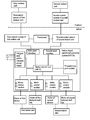
- FIG. 1 is a block diagram of motors and motor controllers in an electrical equipment in the prior art
- FIG. 2 is a block diagram of an indoor digital centralized controller system in accordance with one embodiment of the invention.
- FIG. 3 is a connection diagram of an indoor digital centralized controller system in accordance with one embodiment of the invention.
- FIG. 4 is a schematic diagram of a brushless DC motor in accordance with one embodiment of the invention.
- FIG. 5 is a cross-sectional view of FIG. 4 ;
- FIG. 6 is a first electrical connection diagram of a motor control module in accordance with one embodiment of the invention.
- FIG. 7 is a second electrical connection diagram of a motor control module in accordance with one embodiment of the invention.
- FIG. 8 is a third electrical connection diagram of a motor control module in accordance with one embodiment of the invention.
- FIG. 9 is a fourth electrical connection diagram of a motor control module in accordance with one embodiment of the invention.
- FIG. 10 is a fifth electrical connection diagram of a motor control module in accordance with one embodiment of the invention.
- FIG. 11 is a wiring diagram of an indoor digital centralized controller system used in an air conditioning system comprising single indoor unit and single outdoor unit in accordance with one embodiment of the invention
- FIG. 12 is a first block diagram of an indoor digital centralized controller system used in an air conditioning system comprising dual indoor units and dual outdoor units in accordance with one embodiment of the invention
- FIG. 13 is a developed view of FIG. 12 ;
- FIG. 14 is a second block diagram of an indoor digital centralized controller system used in an air conditioning system comprising dual indoor units and dual outdoor units in accordance with one embodiment of the invention.
- FIG. 15 is a block diagram of an indoor digital centralized controller system used in a heating/cooling device in accordance with one embodiment of the invention.
- an indoor digital centralized controller system is connected to a controller of an application system.
- the indoor digital centralized controller system is configured to accept orders from the controller of the application system and control at least one motor to work.
- the indoor digital centralized controller system comprises a power supply, a master control unit (MCU), a plurality of motor control modules, a programming port module, and an input interface.
- the power supply is configured to supply power for circuits.
- the MCU is connected to and communicates with the controller of the application system via the input interface.
- An outer computer is capable of rewriting control programs of the MCU via the programming port module.
- the MCU is connected to a motor via a motor control module.
- the motor comprises a stator assembly, a rotor assembly, and a shell assembly.
- the stator assembly and the rotor assembly are coupled magnetically.
- the stator assembly comprises a stator core and a coil winding wound around the stator core.
- the coil winding is configured to acquire alternating current from the motor control module and generate rotating magnetic field to drive a rotor to rotate.
- the motor controlled by the indoor digital centralized controller system is an AC motor or a brushless DC motor.
- the brushless DC motor is not controlled by the motor controller.
- the brushless DC motor 100 comprises a shell assembly 101 , a stator assembly 102 , a rotor assembly 103 , and a detecting unit 104 of rotor position.
- the detecting unit 104 of rotor position is optional.
- the motor controlled by the indoor DCCS is a common three-phase alternating current motor, a permanent split-capacitor (PSC) alternating current motor, or an Electronically Commutated Motor (ECM) not having a motor controller.
- PSC permanent split-capacitor
- ECM Electronically Commutated Motor
- the motor control module is a control module of AC motor or a control module of brushless DC motor.
- the control module of AC motor comprises a relay and a drive circuit.
- the control module of brushless DC motor comprises a detecting unit 104 of rotor position, a microprocessor, and an inverter unit.
- the detecting unit 104 of rotor position is configured to transmit rotor position data of a permanent magnet motor to the microprocessor.
- the microprocessor is configured to control the inverter unit to output alternating current to the coil winding on the stator core.
- the microprocessor is connected to and communicates with the MCU.
- the motor control module is a control module of AC motor or a control module of brushless DC motor.
- the control module of AC motor comprises a relay and a drive circuit.
- the control module of brushless DC motor comprises a detecting unit of phase current, a microprocessor, and an inverter unit.
- the detecting unit of phase current is configured to transmit current data of a permanent magnet motor to the microprocessor.
- the microprocessor is configured to control the inverter unit to output alternating current to the coil winding on the stator core.
- the microprocessor is connected to and communicates with the MCU.
- the motor control module is a control module of AC motor or a control module of brushless DC motor.
- the control module of AC motor comprises a relay and a drive circuit.
- the control module of brushless DC motor comprises a detecting unit of rotor position and an inverter unit.
- the detecting unit of rotor position is configured to transmit rotor position data in a permanent magnet motor to the MCU.
- the MCU is configured to control the inverter unit to output alternating current to the coil winding on the stator core.
- the motor control module is a control module of AC motor or a control module of brushless DC motor.
- the control module of AC motor comprises a relay and a drive circuit.
- the control module of brushless DC motor comprises a detecting unit of phase current and an inverter unit.
- the detecting unit of phase current is configured to transmit current data of a permanent magnet motor to the MCU.
- the MCU is configured to control the inverter unit to output alternating current to the coil winding on the stator core.
- the control module of AC motor comprises a relay and a drive circuit.
- the motor control module comprises four control modules of brushless DC motor to control four brushless DC motors.
- the motor control module comprises two control modules of brushless DC motor and two control modules of AC motor.
- the two control modules of brushless DC motor are configured to control two permanent magnetic motors, and the two control modules of AC motor are configured to control two AC motors.
- the motor control module comprises three control modules of brushless DC motor and a control module of AC motor.
- the three control modules of brushless DC motor are configured to control three brushless DC motors, and the control module of AC motor is configured to control one AC motor.
- the digital centralized controller system is an indoor unit, for example, an air handling unit, a gas furnace, a fan coil unit, or a variable air volume (VAV) terminal unit.
- the digital centralized controller system is invented to control the digital motor core.
- the digital motor core as shown in FIGS. 4-6 , comprises a stator assembly 102 , a rotor assembly 103 , and a Hall sensor assembly (equals to the detecting unit 104 of rotor position). All of the motors are centralized in the DCCS, and the purpose of using the DCCS is to manipulate certain type of thermostat and main system controller, such as the existing integrated furnace controller, or a compatible third-party outdoor control unit.
- the DCCS is used as a substitution for relay board, system controller, or blower system in a residential air-conditioning processing or fan system, not as a substitution for the integrated furnace controller.
- the DCCS is intended to be applied to the following products: Type I: a digital controlled fan motor of 1 hp, as in the application of residential air-conditioning system, at a voltage between 208 and 240 Vac; Type II: a digital controlled fan motor, combined with a digital induced draft fan, between 1 ⁇ 3 hp and 1 hp, as in the application of residential furnace, at a voltage of 115 Vac; Type III: two digital motors of 1 hp, as in a commercial fan coil unit, at a voltage between 115 and 277 Vac; Type IV: two digital blower motors, combined with two induced draft fan.
- the power supply is an adaptive input power supply, and has a wide range of input voltage: 115 V, 205-230 V, 277 V, 460 V, etc.
- Interface part of the motor only three-phase (U, V, W) line voltage input is feasible; when a Hall detection element exists, the motors comprises signal wire to feed Hall signals and low-voltage power wire.
- an air conditioning system comprising single indoor unit and single outdoor unit, comprising an outdoor unit, a control system of outdoor unit, and an indoor unit.
- the outdoor unit comprises a compressor and a cooling fan.
- the compressor and the cooling fan are controlled by the control system of outdoor unit.
- the indoor unit comprises an indoor digital centralized controller system.
- the indoor digital centralized controller system comprises a power supply, a master control unit (MCU), a motor control module, a programming port module, a first input interface, a second input interface, two relays, and two drive circuits.
- the power supply is configured to supply power for circuits.
- the MCU is connected to and communicates with a controller of indoor application system via the first input interface and the second input interface.
- An outer computer is capable of rewriting control programs of the MCU via the programming port module.
- the MCU is connected to a motor via the motor control module to drive a blower.
- the motor is a brushless DC motor.
- the motor comprises a stator assembly, a permanent magnetic rotor assembly, and a shell assembly.
- the stator assembly and the permanent magnetic rotor assembly are coupled magnetically.
- the stator assembly comprises a stator core and a coil winding wound around the stator core.
- the coil winding is configured to acquire alternating current from the motor control module and generate rotating magnetic field to drive a rotor to rotate.
- the control system of outdoor unit is connected to and communicates with the MCU via the first input interface.
- a thermostat is connected to and communicates with the MCU via the second input interface.
- the MCU controls an electrical heater via the two relays and the two drive circuits.
- the motor 100 is a brushless DC motor not having a motor controller.
- the two relays and the two drive circuits are a first relay, a first drive circuit, a second relay, and a second drive circuit.
- the motor 100 is configured to drive the blower in the indoor unit.
- an air conditioning system comprising dual indoor units and dual outdoor units, comprises a first outdoor unit, a first control system of the first outdoor unit, a second outdoor unit, a second control system of the second outdoor unit, a first indoor unit, a third control system of the first indoor unit, a second indoor unit, and a fourth control system of the first indoor unit.
- the first outdoor unit comprises a first compressor and a first cooling fan. The first compressor and the first cooling fan are controlled by the first control system.
- the second outdoor unit comprises a second compressor and a second cooling fan. The second compressor and the second cooling fan are controlled by the second control system.
- the first control system is connected to and communicates with the third control system.
- the second control system is connected to and communicates with the fourth control system.
- a thermostat is connected to the third control system and the fourth control system.
- the first indoor unit comprises a first blower and a first induced draft fan.
- the second indoor unit comprises a second blower and a second induced draft fan.
- the first indoor unit and the second indoor unit comprise an indoor digital centralized controller system.
- the indoor digital centralized controller system comprises a power supply, a master control unit (MCU), four motor control modules, a programming port module, a first input interface, a second input interface, two relays, and two drive circuits.
- the power supply is configured to supply power for circuits.
- the MCU is connected to and communicates with the third control system via the first input interface.
- the MCU is connected to and communicates with the fourth control system via a second input interface.
- An outer computer is capable of rewriting control programs of the MCU via the programming port module.
- the MCU is connected to four motors via the four motor control modules.
- the four motors are respectively disposed on the first blower, the first induced draft fan, the second blower and the second induced draft fan.
- the motors each comprise a stator assembly, a rotor assembly, and a shell assembly.
- the stator assembly and the rotor assembly are coupled magnetically.
- the stator assembly comprises a stator core and a coil winding wound around the stator core. The coil winding is configured to acquire alternating current from the motor control modules and generate rotating magnetic field to drive a rotor to rotate.
- the first blower, the first induced draft fan, the second blower, and the second induced draft fan use brushless DC motors not having motor controllers. Or the first blower and the second blower use brushless DC motor not having motor controllers, and the first induced draft fan and the second induced draft fan use AC motors.
- the thermostat of the air conditioning system controls two indoor units/outdoor units.
- the key point of the control logic is “the two indoor units/outdoor units having identical air volume are simultaneously actuated and halted; error occurs in one, and the other is stopped and reports error”.
- the first outdoor unit comprises a first compressor and a first cooling fan. The first compressor and the first cooling fan are controlled by the first control system.
- the second outdoor unit comprises a second compressor and a second cooling fan. The second compressor and the second cooling fan are controlled by the second control system.
- the first control system is connected to and communicates with the third control system.
- the second control system is connected to and communicates with the fourth control system.
- a thermostat is connected to the third control system and the fourth control system.
- the first indoor unit comprises a first blower and a first induced draft fan.
- the second indoor unit comprises a second blower and a second induced draft fan.
- the first indoor unit and the second indoor unit comprise two indoor digital centralized controller systems.
- the indoor digital centralized controller systems each comprise a power supply, a master control unit (MCU), two motor control modules, a programming port module, a first input interface, and a second input interface.
- the power supply is configured to supply power for circuits.
- the MCU of a first indoor digital centralized controller system (DCCS) is connected to and communicates with the third control system via the first input interface of the first indoor DCCS.
- DCCS first indoor digital centralized controller system
- the MCU of a second indoor DCCS is connected to and communicates with the fourth control system via the first input interface of the second indoor DCCS.
- the two indoor digital centralized controller systems are connected via two second input interfaces.
- An outer computer is capable of rewriting control programs of the MCU via the programming port module.
- the MCU of a first indoor DCCS is connected to two motors via the two motor control modules of the first indoor DCCS, and the MCU of the second indoor DCCS is connected to two other motors via the two motor control modules of the second indoor DCCS.
- Four motors are respectively disposed on the first blower, the first induced draft fan, the second blower and the second induced draft fan.
- the motors each comprise a stator assembly, a rotor assembly, and a shell assembly.
- the stator assembly and the rotor assembly are coupled magnetically.
- the stator assembly comprises a stator core and a coil winding wound around the stator core.
- the coil winding is configured to acquire alternating current from the motor control modules and generate rotating magnetic field to drive a rotor to rotate.
- the first blower, the first induced draft fan, the second blower, and the second induced draft fan use brushless DC motors not having motor controllers. Or the first blower and the second blower use brushless DC motor not having motor controllers, and the first induced draft fan and the second induced draft fan use AC motors.
- a heating/cooling device comprises a pulse width modulation (PWM) master controller, a thermostat, and an indoor digital centralized controller system.
- the indoor digital centralized controller system comprises a power supply, a master control unit (MCU), two motor control modules, a programming port module, and a PWM signal input interface.
- the power supply is configured to supply power for circuits.
- the MCU is connected to and communicates with the PWM master controller via the PWM signal input interface.
- An outer computer is capable of rewriting control programs of the MCU via the programming port module.
- the MCU sends feedback signals to the PWM master controller.
- the MCU is connected to a motor of a first blower and a motor of a second blower via the two motor control modules.
- the motors are brushless DC motors.
- the motors each comprise a stator assembly, a rotor assembly, and a shell assembly.
- the stator assembly and the rotor assembly are coupled magnetically.
- the stator assembly comprises a stator core and a coil winding wound around the stator core.
- the coil winding is configured to acquire alternating current from the motor control modules and generate rotating magnetic field to drive a rotor to rotate.
- the cooling or heating device is a compressor, resistance wires, gas furnace, a water heater/cooler.
Landscapes
- Engineering & Computer Science (AREA)
- Chemical & Material Sciences (AREA)
- Combustion & Propulsion (AREA)
- Mechanical Engineering (AREA)
- General Engineering & Computer Science (AREA)
- Physics & Mathematics (AREA)
- Signal Processing (AREA)
- Fuzzy Systems (AREA)
- Mathematical Physics (AREA)
- Thermal Sciences (AREA)
- General Physics & Mathematics (AREA)
- Automation & Control Theory (AREA)
- Human Computer Interaction (AREA)
- Control Of Multiple Motors (AREA)
- Control Of Motors That Do Not Use Commutators (AREA)
Applications Claiming Priority (4)
| Application Number | Priority Date | Filing Date | Title |
|---|---|---|---|
| CN201410767224.5 | 2014-12-11 | ||
| CN201410767224 | 2014-12-11 | ||
| CN201410767224.5A CN105737325B (zh) | 2014-12-11 | 2014-12-11 | 一种单机空调系统及双机空调系统 |
| PCT/CN2015/071485 WO2016090734A1 (zh) | 2014-12-11 | 2015-01-23 | 室内数字集中控制系统及其应用的空调、取暖或制冷设备 |
Related Parent Applications (1)
| Application Number | Title | Priority Date | Filing Date |
|---|---|---|---|
| PCT/CN2015/071485 Continuation-In-Part WO2016090734A1 (zh) | 2014-12-11 | 2015-01-23 | 室内数字集中控制系统及其应用的空调、取暖或制冷设备 |
Publications (2)
| Publication Number | Publication Date |
|---|---|
| US20170276390A1 US20170276390A1 (en) | 2017-09-28 |
| US10073473B2 true US10073473B2 (en) | 2018-09-11 |
Family
ID=56106525
Family Applications (1)
| Application Number | Title | Priority Date | Filing Date |
|---|---|---|---|
| US15/619,564 Active US10073473B2 (en) | 2014-12-11 | 2017-06-12 | Indoor digital centralized controller system, air conditioning system comprising the same, and heating/cooling device comprising the same |
Country Status (3)
| Country | Link |
|---|---|
| US (1) | US10073473B2 (zh) |
| CN (1) | CN105737325B (zh) |
| WO (1) | WO2016090734A1 (zh) |
Families Citing this family (3)
| Publication number | Priority date | Publication date | Assignee | Title |
|---|---|---|---|---|
| CN114070172A (zh) * | 2020-08-07 | 2022-02-18 | 中山大洋电机股份有限公司 | 一种带有冗余控制的电机控制单元及其组合方法 |
| DE112021004339T5 (de) * | 2020-08-18 | 2023-06-07 | Regal Beloit America, Inc. | Elektrischer Motor und Verwendungsverfahren |
| CN114151936A (zh) * | 2020-09-07 | 2022-03-08 | 中山大洋电机股份有限公司 | 一种hvac系统控制单元及hvac系统 |
Citations (19)
| Publication number | Priority date | Publication date | Assignee | Title |
|---|---|---|---|---|
| US4205381A (en) * | 1977-08-31 | 1980-05-27 | United Technologies Corporation | Energy conservative control of heating, ventilating, and air conditioning (HVAC) systems |
| US4212078A (en) * | 1977-12-27 | 1980-07-08 | United Technologies Corporation | Computer controlled facility management system (FMS) |
| US4253153A (en) * | 1979-06-28 | 1981-02-24 | United Technologies Corporation | Energy conservative control of terminal reheat heating, ventilating, and air conditioning (HVAC) systems |
| US5775116A (en) * | 1996-04-09 | 1998-07-07 | Sanyo Electric Co., Ltd. | Defrosting control method for air conditioner |
| US6305187B1 (en) * | 2000-02-14 | 2001-10-23 | Hiroaki Tsuboe | Air-conditioner, outdoor unit and refrigeration unit |
| US6755034B2 (en) * | 2002-05-27 | 2004-06-29 | Lg Electronics Inc. | Apparatus for preventing overload of air conditioner and method thereof |
| US6843066B2 (en) * | 2002-12-10 | 2005-01-18 | Lg Electronics Inc. | Air conditioning system and method for controlling the same |
| US6993421B2 (en) * | 1999-07-30 | 2006-01-31 | Oshkosh Truck Corporation | Equipment service vehicle with network-assisted vehicle service and repair |
| US7089088B2 (en) * | 2003-01-24 | 2006-08-08 | Tecumseh Products Company | Integrated HVACR control and protection system |
| US20070012052A1 (en) * | 2005-02-23 | 2007-01-18 | Emerson Electric Co. | Interactive control system for an HVAC system |
| US7184866B2 (en) * | 1999-07-30 | 2007-02-27 | Oshkosh Truck Corporation | Equipment service vehicle with remote monitoring |
| US7277782B2 (en) * | 2001-01-31 | 2007-10-02 | Oshkosh Truck Corporation | Control system and method for electric vehicle |
| US7299648B2 (en) * | 2003-07-31 | 2007-11-27 | Patentbank Co., Ltd. | Refrigeration system of air conditioning apparatuses with bypass line between inlet and outlet of compressor |
| US7437882B2 (en) * | 2000-02-14 | 2008-10-21 | Hitachi Air Conditioning Systems Co., Ltd. | Apparatus for driving a compressor and a refrigerating air conditioner |
| US20100186441A1 (en) * | 2006-11-29 | 2010-07-29 | Lg Electronics Inc. | Multi-air conditioner |
| US20130110376A1 (en) * | 2011-11-01 | 2013-05-02 | Ford Global Technologies, Llc | Method and system for engine control |
| US20130110374A1 (en) * | 2011-11-01 | 2013-05-02 | Ford Global Technologies, Llc | Method and system for engine control |
| US9601919B2 (en) * | 2011-10-31 | 2017-03-21 | Trane International Inc. | Time delay with control voltage sensing |
| US9835360B2 (en) * | 2009-09-30 | 2017-12-05 | Thermo Fisher Scientific (Asheville) Llc | Refrigeration system having a variable speed compressor |
Family Cites Families (10)
| Publication number | Priority date | Publication date | Assignee | Title |
|---|---|---|---|---|
| JP2874107B2 (ja) * | 1993-05-14 | 1999-03-24 | 株式会社クボタ | タック紙用印字発券方法 |
| CN1247410A (zh) * | 1999-03-30 | 2000-03-15 | 汪大明 | 电机集中控制系统装置 |
| JP4217738B2 (ja) * | 2006-12-25 | 2009-02-04 | 日立アプライアンス株式会社 | 空気調和機 |
| CN102064751B (zh) * | 2009-11-17 | 2013-03-27 | 深圳市博巨兴实业发展有限公司 | 双变频控制系统 |
| CN102230658B (zh) * | 2010-02-01 | 2013-09-11 | 中山大洋电机制造有限公司 | 一种空调风机电机控制器及其控制方法 |
| CN201844510U (zh) * | 2010-11-08 | 2011-05-25 | 郑州市锦飞汽车电气系统有限公司 | 汽车空调控制器 |
| CN202066160U (zh) * | 2011-04-26 | 2011-12-07 | 浙江为民能源科技有限公司 | 中央空调集控系统中空调箱电机变频控制装置 |
| CN202121547U (zh) * | 2011-07-22 | 2012-01-18 | 江门天诚溶剂制品有限公司 | 一种利用dcs集中控制电机的控制系统 |
| CN102748834B (zh) * | 2012-07-21 | 2014-08-13 | 中山大洋电机股份有限公司 | 一种家用中央空调的hvac控制系统 |
| CN102748835B (zh) * | 2012-07-21 | 2014-06-18 | 中山大洋电机股份有限公司 | 一种家用中央空调分体机的控制系统 |
-
2014
- 2014-12-11 CN CN201410767224.5A patent/CN105737325B/zh active Active
-
2015
- 2015-01-23 WO PCT/CN2015/071485 patent/WO2016090734A1/zh not_active Ceased
-
2017
- 2017-06-12 US US15/619,564 patent/US10073473B2/en active Active
Patent Citations (26)
| Publication number | Priority date | Publication date | Assignee | Title |
|---|---|---|---|---|
| US4205381A (en) * | 1977-08-31 | 1980-05-27 | United Technologies Corporation | Energy conservative control of heating, ventilating, and air conditioning (HVAC) systems |
| US4212078A (en) * | 1977-12-27 | 1980-07-08 | United Technologies Corporation | Computer controlled facility management system (FMS) |
| US4253153A (en) * | 1979-06-28 | 1981-02-24 | United Technologies Corporation | Energy conservative control of terminal reheat heating, ventilating, and air conditioning (HVAC) systems |
| US5775116A (en) * | 1996-04-09 | 1998-07-07 | Sanyo Electric Co., Ltd. | Defrosting control method for air conditioner |
| US6993421B2 (en) * | 1999-07-30 | 2006-01-31 | Oshkosh Truck Corporation | Equipment service vehicle with network-assisted vehicle service and repair |
| US7184866B2 (en) * | 1999-07-30 | 2007-02-27 | Oshkosh Truck Corporation | Equipment service vehicle with remote monitoring |
| US6305187B1 (en) * | 2000-02-14 | 2001-10-23 | Hiroaki Tsuboe | Air-conditioner, outdoor unit and refrigeration unit |
| US6505480B2 (en) * | 2000-02-14 | 2003-01-14 | Hitachi Ltd. | Air-conditioner, outdoor unit and refrigeration unit |
| US7437882B2 (en) * | 2000-02-14 | 2008-10-21 | Hitachi Air Conditioning Systems Co., Ltd. | Apparatus for driving a compressor and a refrigerating air conditioner |
| US6772607B2 (en) * | 2000-02-14 | 2004-08-10 | Hitachi, Ltd. | Refrigerating device |
| US20100301668A1 (en) * | 2001-01-31 | 2010-12-02 | Oshkosh Corporation | Control system and method for electric vehicle |
| US7711460B2 (en) * | 2001-01-31 | 2010-05-04 | Oshkosh Corporation | Control system and method for electric vehicle |
| US7689332B2 (en) * | 2001-01-31 | 2010-03-30 | Oshkosh Corporation | Control system and method for electric vehicle |
| US7277782B2 (en) * | 2001-01-31 | 2007-10-02 | Oshkosh Truck Corporation | Control system and method for electric vehicle |
| US6755034B2 (en) * | 2002-05-27 | 2004-06-29 | Lg Electronics Inc. | Apparatus for preventing overload of air conditioner and method thereof |
| US6843066B2 (en) * | 2002-12-10 | 2005-01-18 | Lg Electronics Inc. | Air conditioning system and method for controlling the same |
| US7089088B2 (en) * | 2003-01-24 | 2006-08-08 | Tecumseh Products Company | Integrated HVACR control and protection system |
| US7299648B2 (en) * | 2003-07-31 | 2007-11-27 | Patentbank Co., Ltd. | Refrigeration system of air conditioning apparatuses with bypass line between inlet and outlet of compressor |
| US20070012052A1 (en) * | 2005-02-23 | 2007-01-18 | Emerson Electric Co. | Interactive control system for an HVAC system |
| US8550368B2 (en) * | 2005-02-23 | 2013-10-08 | Emerson Electric Co. | Interactive control system for an HVAC system |
| US20100186441A1 (en) * | 2006-11-29 | 2010-07-29 | Lg Electronics Inc. | Multi-air conditioner |
| US8245523B2 (en) * | 2006-11-29 | 2012-08-21 | Lg Electronics Inc. | Multi-air conditioner |
| US9835360B2 (en) * | 2009-09-30 | 2017-12-05 | Thermo Fisher Scientific (Asheville) Llc | Refrigeration system having a variable speed compressor |
| US9601919B2 (en) * | 2011-10-31 | 2017-03-21 | Trane International Inc. | Time delay with control voltage sensing |
| US20130110376A1 (en) * | 2011-11-01 | 2013-05-02 | Ford Global Technologies, Llc | Method and system for engine control |
| US20130110374A1 (en) * | 2011-11-01 | 2013-05-02 | Ford Global Technologies, Llc | Method and system for engine control |
Also Published As
| Publication number | Publication date |
|---|---|
| US20170276390A1 (en) | 2017-09-28 |
| CN105737325A (zh) | 2016-07-06 |
| CN105737325B (zh) | 2018-10-26 |
| WO2016090734A1 (zh) | 2016-06-16 |
Similar Documents
| Publication | Publication Date | Title |
|---|---|---|
| US10027206B2 (en) | Blower motor for HVAC systems | |
| US7990092B2 (en) | Blower motor for HVAC systems | |
| US8294393B2 (en) | Blower motor for HVAC systems | |
| US20110260671A1 (en) | Apparatus for selecting speed of electrically commutated motor for use in hvac system | |
| US8362737B2 (en) | Blower motor for HVAC systems | |
| US8362736B2 (en) | Blower motor for HVAC systems | |
| US8049459B2 (en) | Blower motor for HVAC systems | |
| CN104467558A (zh) | 一种替换psc电机的ecm电机参数设定方法 | |
| CN106154871B (zh) | 一种电器设备的通风管道堵塞程度实时显示控制方法 | |
| US10073473B2 (en) | Indoor digital centralized controller system, air conditioning system comprising the same, and heating/cooling device comprising the same | |
| US9071183B2 (en) | Methods and systems for providing combined blower motor and draft inducer motor control | |
| US8013551B2 (en) | Blower motor for HVAC systems | |
| US9093934B2 (en) | Methods and systems for controlling a motor | |
| US10234165B2 (en) | HVAC control system for household central air conditioning | |
| US9859825B2 (en) | Centralized motor controller | |
| CN104579109B (zh) | 一种电子换相电机的控制方法 | |
| CN105588277A (zh) | 空调系统及其控制方法 | |
| US12334780B2 (en) | Electronically commutated motor zero-watt standby power consumption | |
| TWI555324B (zh) | DC brushless motor control system for AC power supply | |
| JPH06307659A (ja) | 空気調和機 | |
| CN106533321B (zh) | 电机控制电路及使用方法 | |
| JPH07293979A (ja) | 空気調和機 | |
| JPH10126862A (ja) | 電流検出によるシステム制御装置 |
Legal Events
| Date | Code | Title | Description |
|---|---|---|---|
| AS | Assignment |
Owner name: ZHONGSHAN BROAD-OCEAN MOTOR CO., LTD., CHINA Free format text: ASSIGNMENT OF ASSIGNORS INTEREST;ASSIGNORS:HU, GE;ZHANG, ZHENG;ZHAO, YONG;REEL/FRAME:042671/0108 Effective date: 20170307 |
|
| STCF | Information on status: patent grant |
Free format text: PATENTED CASE |
|
| MAFP | Maintenance fee payment |
Free format text: PAYMENT OF MAINTENANCE FEE, 4TH YEAR, LARGE ENTITY (ORIGINAL EVENT CODE: M1551); ENTITY STATUS OF PATENT OWNER: LARGE ENTITY Year of fee payment: 4 |
|
| MAFP | Maintenance fee payment |
Free format text: PAYMENT OF MAINTENANCE FEE, 8TH YEAR, LARGE ENTITY (ORIGINAL EVENT CODE: M1552); ENTITY STATUS OF PATENT OWNER: LARGE ENTITY Year of fee payment: 8 |