US10072580B2 - Method and system for the emergency start-up of an energy generator set - Google Patents
Method and system for the emergency start-up of an energy generator set Download PDFInfo
- Publication number
- US10072580B2 US10072580B2 US14/396,235 US201314396235A US10072580B2 US 10072580 B2 US10072580 B2 US 10072580B2 US 201314396235 A US201314396235 A US 201314396235A US 10072580 B2 US10072580 B2 US 10072580B2
- Authority
- US
- United States
- Prior art keywords
- positive displacement
- displacement motor
- generator set
- energy generator
- shaft
- Prior art date
- Legal status (The legal status is an assumption and is not a legal conclusion. Google has not performed a legal analysis and makes no representation as to the accuracy of the status listed.)
- Active, expires
Links
- 238000000034 method Methods 0.000 title claims description 10
- 238000006073 displacement reaction Methods 0.000 claims abstract description 65
- 230000008878 coupling Effects 0.000 claims abstract description 30
- 238000010168 coupling process Methods 0.000 claims abstract description 30
- 238000005859 coupling reaction Methods 0.000 claims abstract description 30
- 230000005540 biological transmission Effects 0.000 claims abstract description 7
- 239000003999 initiator Substances 0.000 claims abstract description 6
- 239000007789 gas Substances 0.000 claims description 79
- 238000002485 combustion reaction Methods 0.000 claims description 13
- 238000013519 translation Methods 0.000 claims description 6
- 230000001960 triggered effect Effects 0.000 claims description 4
- 230000006835 compression Effects 0.000 claims description 3
- 238000007906 compression Methods 0.000 claims description 3
- 238000012360 testing method Methods 0.000 claims description 3
- 239000007858 starting material Substances 0.000 abstract description 13
- 230000007246 mechanism Effects 0.000 abstract description 3
- 230000004043 responsiveness Effects 0.000 abstract description 2
- 239000002184 metal Substances 0.000 description 5
- 229910052751 metal Inorganic materials 0.000 description 5
- 239000003380 propellant Substances 0.000 description 5
- 239000000567 combustion gas Substances 0.000 description 4
- 239000012530 fluid Substances 0.000 description 4
- 238000009529 body temperature measurement Methods 0.000 description 2
- 238000009833 condensation Methods 0.000 description 2
- 230000005494 condensation Effects 0.000 description 2
- 238000005516 engineering process Methods 0.000 description 2
- 238000010438 heat treatment Methods 0.000 description 2
- 230000000737 periodic effect Effects 0.000 description 2
- 230000035484 reaction time Effects 0.000 description 2
- WJYVXARRCUTRBW-HNNXBMFYSA-N (3s)-3-[[6-[[[3-(acetylsulfamoyl)phenyl]sulfonylamino]methyl]pyridine-3-carbonyl]amino]-4-oxobutanoic acid Chemical compound CC(=O)NS(=O)(=O)C1=CC=CC(S(=O)(=O)NCC=2N=CC(=CC=2)C(=O)N[C@@H](CC(O)=O)C=O)=C1 WJYVXARRCUTRBW-HNNXBMFYSA-N 0.000 description 1
- 230000004913 activation Effects 0.000 description 1
- 238000006243 chemical reaction Methods 0.000 description 1
- 230000000295 complement effect Effects 0.000 description 1
- 239000004020 conductor Substances 0.000 description 1
- 238000005553 drilling Methods 0.000 description 1
- 238000004870 electrical engineering Methods 0.000 description 1
- 230000004907 flux Effects 0.000 description 1
- 230000020169 heat generation Effects 0.000 description 1
- 238000007654 immersion Methods 0.000 description 1
- 238000002347 injection Methods 0.000 description 1
- 239000007924 injection Substances 0.000 description 1
- 238000007689 inspection Methods 0.000 description 1
- 238000004519 manufacturing process Methods 0.000 description 1
- 238000002844 melting Methods 0.000 description 1
- 230000008018 melting Effects 0.000 description 1
- 238000012806 monitoring device Methods 0.000 description 1
- 230000007420 reactivation Effects 0.000 description 1
- 239000000523 sample Substances 0.000 description 1
- 238000007789 sealing Methods 0.000 description 1
- 125000006850 spacer group Chemical group 0.000 description 1
Images


Classifications
-
- F—MECHANICAL ENGINEERING; LIGHTING; HEATING; WEAPONS; BLASTING
- F02—COMBUSTION ENGINES; HOT-GAS OR COMBUSTION-PRODUCT ENGINE PLANTS
- F02C—GAS-TURBINE PLANTS; AIR INTAKES FOR JET-PROPULSION PLANTS; CONTROLLING FUEL SUPPLY IN AIR-BREATHING JET-PROPULSION PLANTS
- F02C7/00—Features, components parts, details or accessories, not provided for in, or of interest apart form groups F02C1/00 - F02C6/00; Air intakes for jet-propulsion plants
- F02C7/26—Starting; Ignition
- F02C7/268—Starting drives for the rotor, acting directly on the rotor of the gas turbine to be started
- F02C7/27—Fluid drives
- F02C7/272—Fluid drives generated by cartridges
-
- F—MECHANICAL ENGINEERING; LIGHTING; HEATING; WEAPONS; BLASTING
- F02—COMBUSTION ENGINES; HOT-GAS OR COMBUSTION-PRODUCT ENGINE PLANTS
- F02C—GAS-TURBINE PLANTS; AIR INTAKES FOR JET-PROPULSION PLANTS; CONTROLLING FUEL SUPPLY IN AIR-BREATHING JET-PROPULSION PLANTS
- F02C7/00—Features, components parts, details or accessories, not provided for in, or of interest apart form groups F02C1/00 - F02C6/00; Air intakes for jet-propulsion plants
- F02C7/26—Starting; Ignition
- F02C7/268—Starting drives for the rotor, acting directly on the rotor of the gas turbine to be started
- F02C7/275—Mechanical drives
-
- F—MECHANICAL ENGINEERING; LIGHTING; HEATING; WEAPONS; BLASTING
- F02—COMBUSTION ENGINES; HOT-GAS OR COMBUSTION-PRODUCT ENGINE PLANTS
- F02N—STARTING OF COMBUSTION ENGINES; STARTING AIDS FOR SUCH ENGINES, NOT OTHERWISE PROVIDED FOR
- F02N13/00—Starting of engines, or driving of starting apparatus by use of explosives, e.g. stored in cartridges
-
- F—MECHANICAL ENGINEERING; LIGHTING; HEATING; WEAPONS; BLASTING
- F02—COMBUSTION ENGINES; HOT-GAS OR COMBUSTION-PRODUCT ENGINE PLANTS
- F02N—STARTING OF COMBUSTION ENGINES; STARTING AIDS FOR SUCH ENGINES, NOT OTHERWISE PROVIDED FOR
- F02N15/00—Other power-operated starting apparatus; Component parts, details, or accessories, not provided for in, or of interest apart from groups F02N5/00 - F02N13/00
- F02N15/10—Safety devices not otherwise provided for
-
- Y—GENERAL TAGGING OF NEW TECHNOLOGICAL DEVELOPMENTS; GENERAL TAGGING OF CROSS-SECTIONAL TECHNOLOGIES SPANNING OVER SEVERAL SECTIONS OF THE IPC; TECHNICAL SUBJECTS COVERED BY FORMER USPC CROSS-REFERENCE ART COLLECTIONS [XRACs] AND DIGESTS
- Y02—TECHNOLOGIES OR APPLICATIONS FOR MITIGATION OR ADAPTATION AGAINST CLIMATE CHANGE
- Y02T—CLIMATE CHANGE MITIGATION TECHNOLOGIES RELATED TO TRANSPORTATION
- Y02T50/00—Aeronautics or air transport
- Y02T50/60—Efficient propulsion technologies, e.g. for aircraft
-
- Y02T50/671—
Definitions
- the invention relates to a method and to a system for the emergency start-up of an energy generator set in critical situations where the dedicated traction system has stopped or is inadequate to meet requirements.
- a gas turbine can currently be restarted using three types of starter with different physical features
- Pneumatic and hydraulic starters have drawbacks connected to their mass and size. Moreover, they require periodic inspections of their casings and replacement of the pressurised reservoirs.
- the emergency situations that might arise in the applications mentioned above require reaction times of approximately a few seconds, particularly two to three seconds, or even less than a second, to allow a sufficient safety margin for emergency starting or restarting.
- the invention seeks to provide emergency starters that allow responsiveness of this order of magnitude, namely within a few seconds, without having the disadvantages associated with the mass and size of the back-up hydraulic or pneumatic starters mentioned above.
- the present invention proposes coupling an instantaneous gas thrust of pyrotechnic type with a positive displacement transmission generator in conjunction with automatic coupling to/uncoupling from the set that is to be started.
- the object of the present invention is a method for emergency start-up of an energy generator set wherein, if an emergency start-up situation for the set is detected, at least one pyrotechnic gas combustion generator is triggered. Pressurised gases are then generated by this combustion and injected directly into a positive displacement motor with gear wheels, preferably straight-cut. A portion of these gases then rotates the gear wheels of the engine and, simultaneously, the remaining portion of the gases projects a coupling connection between the engine and the set, against a restoring force.
- the connection brings about the transmission of energy by rotating a gear shaft of the positive displacement motor on a driven shaft of the set. When the thrust falls below the restoring force, said force automatically repels the connection and the set is disconnected from the positive displacement motor.
- the invention also relates to a system for the emergency start-up of an energy generator set capable of implementing the above method.
- This system comprises at least one pyrotechnic gas generator connected to an electrical initiator, itself connected to a computer, a positive displacement motor comprising a casing defining an internal space housing straight-cut gear wheels, the pyrotechnic gas generator being coupled to the motor by an inlet in the casing.
- the motor has a connection means capable of moving at one end of the drive shaft centred about a gear-wheel axis of the positive displacement motor, so as to be able to couple this drive shaft to a driven shaft of the set via a centrifugal clutch.
- a return means arranged in abutment is capable of exerting a restoring force against the pressure exerted on the connection means.
- each positive displacement motor typically provides power of approximately 40 kW for around 2.5 seconds for each injection of pyrotechnic gas, with a reaction time of approximately 0.5 seconds.
- the system has suitable sizes and ratings to allow use nominally in the temperature range between ⁇ 30 and +50° C., a range that can be extended to the rated limiting temperatures of the surrounding equipment, for example of approximately 135° C. for the extreme environments mentioned above.
- the ambient operating pressure is between around 60 and 110 kPa.
- FIG. 1 is a diagrammatic view in cross section of a first example of a positive displacement motor of the emergency start-up system according to the invention
- FIGS. 2 a and 2 b are diagrammatic views in longitudinal section of the positive displacement motor according to FIG. 1 , before and after the projection of pyrotechnic gas;
- FIGS. 3 a to 3 c are views in perspective, in cross section along BB and in longitudinal section along CC, of another example of a positive displacement motor of the emergency start-up system according to the invention.
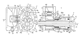
- FIG. 4 is an overall view an example of the emergency start-up system according to the invention, composed of an electronic unit, a pyrotechnic generator and a positive displacement motor;
- FIG. 5 is a sectional view of the electronic unit according to FIG. 4 ;
- FIG. 6 is a sectional view of the pyrotechnic generator according to FIG. 4 ;
- FIG. 7 a is a sectional view of a two-stage positive displacement motor having two spur-pinion motors
- FIG. 7 b is a sectional view of a two-stage positive displacement motor, having a roller motor coupled to a spur-pinion motor;
- FIG. 8 a is an example of mounting a positive displacement motor of a start-up system according to the invention on the shaft of an accessory gearbox of a turbine engine;
- FIG. 8 b is the mounting of this positive displacement motor on a bell housing rigidly connected to a pinion of the accessory gearbox according to FIG. 8 a;
- FIG. 8 c shows the mounting of this positive displacement motor directly on the shaft of the HP spool of the turbine engine according to FIG. 8 a.
- cross section relates to a view in the plane perpendicular to what is described as the longitudinal axis of the motors, which extend mainly along such an axis.
- longitudinal section denotes a sectional view along said longitudinal axis.
- upper or lower refer to relative positions of the wall or face of a device placed in a standard operating position.
- identical reference signs relate to identical components as described in the corresponding passages.
- a first example of a positive displacement motor 1 of an emergency start-up system has a casing 2 defining an internal space E 1 housing two spur pinions 3 a and 3 b, capable of rotating in opposite directions of rotation (arrows Ra and Rb) about drive shafts 4 a and 4 b .
- the casing 2 has two opposite side walls 2 L and 2 L′ substantially symmetrical relative to the longitudinal plane II-II.
- a gas inlet 21 and a gas outlet 22 formed respectively on the walls 2 L and 2 L′, have the same axis A 2 , which extends substantially perpendicular to the walls 2 L and 2 L′, halfway between the gear wheels 3 a and 3 b.
- a linking conduit 2 C is fixed in the gas inlet 21 and in the core of a pyrotechnic gas generator 5 , to allow the propulsion of combustion gases into the motor 1 .
- This gas generator 5 contains a propellant block 51 connected to an ignition cartridge 52 .
- the casing 2 of the motor 1 and the shaft 4 b of the pinion 3 b extend longitudinally along the drive shaft 4 b with the gear-wheel axis X′X, so as to accommodate a shaft 6 of an energy generator set to be restarted.
- the driven shaft 6 passes through the drive shaft 4 b and is rigidly connected outside the shaft 4 b, to a cylindrical centrifugal clutch 7 .
- the centrifugal clutch 7 covers movable annular parts—a piston 8 a, a ferrule 8 b and a support 8 c —for rotatably connecting the drive shaft 4 b and the clutch 7 .
- the drive shaft 4 b is mounted on bearings P 1 and P 2 in the cylindrical extensions 20 a and 20 b of the casing 2
- the shaft 4 a of the pinion 3 a is mounted in the casing 2 by a mechanism 40 with balls and spring plates.
- a conical portion 41 supporting the ferrule 8 b which has a complementary tapered shape.
- a spring 9 arranged in a space capped by the clutch 7 , between the stop 8 c and the ferrule 8 b, bears at one end on the ferrule 8 b and, at the other end, on an end plate 41 F, formed at the end of the conical portion 41 .
- annular space E 2 formed in the extension 20 a of the casing 2 , on the periphery of the drive shaft 4 b, communicates at one end with the internal space E 1 of the motor 1 and, at the other end, with a radial space E 3 closed off by the side face 8 F of the piston 8 a.
- the ferrule 8 b constituted by two half-ferrules held between the piston 8 a and the support 8 c, moves aside radially (arrows F 2 ) by means of the half-ferrules sliding along the conical portion 41 , and then comes into close contact with the centrifugal clutch 7 .
- the clutch is rotated by friction and, simultaneously, rotates the driven shaft 6 of the set to be started.
- the return spring 9 exerts sufficient force to push the ferrule 8 b in the opposite direction to the arrow F 1 and contact between this ferrule and the clutch 7 is broken: the driven shaft 6 is instantly disengaged.
- FIGS. 3 a to 3 c Another example of a positive displacement motor of the emergency start-up system according to the invention is illustrated in the perspective and sectional views in FIGS. 3 a to 3 c.
- the positive displacement motor 100 resembles the preceding positive displacement motor externally, with a casing 120 having two side walls 20 L and 20 L′ and a centrifugal clutch 170 mounted on the cylindrical extension 120 a of the casing around a drive shaft (see FIG. 3 c ).
- An end plate 130 is mounted on this cylindrical extension 120 a via a ring 12 B, to allow the motor to be fixed to a casing of the set to be restarted.
- a gas inlet 121 can be seen on the “upper” wall 12 S of the casing 120 .
- the casing 120 defines an internal space E 11 housing—inside jackets 124 —the two spur pinions 3 a and 3 b of the preceding example, capable of turning in opposite directions of rotation (arrows Ra and Rb) about drive shafts 40 a and 40 b.
- the incoming gases (arrows F 8 ) are separated by a deflector 125 and the jackets have openings 126 through which the gases can circulate within the internal space E 11 .
- the drive shaft 40 b has a central bore 4 A, which is capable of channelling a portion of the combustion gases.
- the two opposite side walls 20 L and 20 L′ of the casing 120 are substantially symmetrical.
- the gas inlet 121 and the gas outlet 122 formed respectively on the “upper” and “lower” walls 12 S and 12 l , have the same axis of symmetry A 2 , which extends in a median plane Pm, parallel to the walls 20 L and 20 L′.
- the gases are discharged (arrow F 10 ) via the openings 126 .
- the rotating connection means between the drive shaft 40 b —mounted on the bearings P 3 and P 4 —and the centrifugal clutch 170 is constituted by a conical piston 18 and a corresponding conical housing 18 L, formed within an annular part 19 rigidly connected to the centrifugal clutch 170 .
- a helical spring 90 is arranged in a bore 180 of the piston 18 , along a rod 42 coming from a stop 43 rigidly connected to the end of the drive shaft 40 b.
- the spring 90 extends between the stop 43 and a shoulder 181 formed at the bottom of the bore 180 of the piston 18 .
- a conduit 140 having a longitudinal portion 14 L and a radial portion 14 R, connects the gas inlet 121 of the casing 120 to the central bore 4 A of the drive shaft 40 b.
- the greater part of the gases rotate the pinions 3 a and 3 b of the motor 100 and the shafts 4 a and 4 b.
- the drive shaft 4 b drives the piston 18 .
- the lesser part of the gases is channelled via the conduit 140 (arrows F 3 , F 4 and F 5 ), towards the central bore 4 A of the shaft 40 b.
- the gases are then propelled against the radial face 18 R of the piston 18 (arrow F 6 ) which moves in translation along the axis X′X of the drive shaft 40 b.
- the piston 18 comes into close contact within its conical housing 18 L, and then rotates by friction the annular part 19 , together with the centrifugal clutch 170 , which is rigidly connected to the part 19 .
- the return spring 90 exerts sufficient force to push the piston 18 in the opposite direction to the arrow F 6 and contact between the piston and the part 19 rigidly connected to the clutch 170 is broken: a driven shaft of the set to be started, in connection with the clutch 170 , is then disengaged.
- FIG. 4 The overall view of an example of the emergency start-up system 10 according to the invention is illustrated in FIG. 4 .
- This system comprises an electronic unit 3 , a pyrotechnic generator 5 and the positive displacement motor 100 . More precisely, the electronic unit 3 is connected via an electrical conduit 11 to the ignition cartridge 52 of the pyrotechnic generator 5 , itself connected to the inlet 121 of the motor 100 via a rigid metal conduit 12 . Moreover, the electronic unit 3 is connected to the computer (not shown) of the set to be started, a turbine engine in the example, via an electrical conduit 13 . Connectors 14 fixed by screws 15 provide the connection between the conduits 11 to 13 and the electronic unit 3 , the pyrotechnic generator 5 and the positive displacement motor 100 .
- This motor 100 has a centrifugal clutch 170 linked to the drive shaft 40 b so as to drive a shaft of the set that is to be started.
- the electronic unit 3 houses a battery 31 as an autonomous source of electrical power, and an electronic control board 32 .
- This board incorporates a heat-sensitive component 33 and a microcontroller 34 for managing the battery 31 , the heat-sensitive component 33 , functional self-tests and alarms triggering the ignition cartridge 52 for the pyrotechnic generator 5 .
- the conductors 11 and 13 are mounted on the unit 3 by means of the connectors 14 .
- the triggering alarms include alarms for detecting potential fires, triggered by the heat-sensitive component 33 , and the alarms controlled by the computer on the basis of data supplied by speed sensors or temperature probes.
- the electronic board 32 incorporates a temperature measurement component 35 managed by the microcontroller 34 , to monitor high temperature values and allow the computer to determine service life without damaging operational safety.
- FIG. 6 A sectional view of the pyrotechnic generator 5 is also illustrated in FIG. 6 .
- This generator is composed of a metal body 53 within which the propellant block 51 is arranged on spacers 54 .
- a layer of inhibitor 55 surrounds the block 51 at its sides.
- a metal cap 56 is fixed firmly to the body 53 to ensure a hermetic seal.
- the ignition cartridge 52 is screwed into a channel 57 formed in the cap 56 and closed by a tip 57 a capable of melting above a predetermined temperature.
- the combustion gases of the propellant ignited by the cartridge 52 exit via a seal 58 a of a tuned nozzle 58 linked to the metal conduit 12 that leads to the positive displacement motor 100 (see FIG. 4 ).
- FIGS. 7 a and 7 b show in section a two-stage positive displacement motor, having respectively either two spur-pinion motors 101 and 102 ( FIG. 7 a ), for example of the same type as the motor 100 , or a roller motor or vane motor 200 (seen in section) and the spur-pinion motor 102 ( FIG. 7 b ).
- the gases released by a pyrotechnic generator are propelled to the inlet 121 or 221 of the first stage (arrows F 7 ), constituted respectively by the spur-pinion motor 101 ( FIG. 7 a ) or by the roller-type or vane-type motor 200 ( FIG. 1 b ), coupled downstream to a second stage mounted in tandem, constituted by the spur-pinion motor 102 .
- the gases are projected towards the inlet 121 (arrows F 8 ) and into (arrows F 9 ) the second motor 102 through the jackets 124 .
- the second motor 102 is advantageously larger in size than the first motor 101 or 200 so as to avoid impeding the first motor.
- the drive shaft 400 or central shaft 600 of the first motor, 101 or 200 respectively, is mounted in the secondary shaft 300 of the second motor 102 (arrows Ft), while the drive shaft 500 of the second motor drives the set to be restarted.
- the gases leave via the outlet 122 of the second motor 102 (arrows F 10 ).
- FIGS. 8 a to 8 c examples of mounting positive displacement motors 1 or 100 of the system according to the invention are illustrated in FIGS. 8 a to 8 c.
- the driven shaft inserted into the drive shaft 4 b of the positive displacement motor 1 is a shaft 61 of the accessory gearbox 71 mounted on the HP spool 80 of the turbine engine 81 .
- the accessory gearbox 71 is fitted with an electric starter 91 , which is a redundant back-up starter component.
- the driven shaft 62 of the turbine engine 81 is mounted on a bell housing rigidly connected to a pinion of the accessory gearbox 71 .
- the bell housing is the centrifugal clutch 170 of the positive displacement motor 100 .
- the driven shaft inserted into the drive shaft 4 b of the positive displacement motor 1 is directly the HP shaft 82 of the HP spool 80 of the turbine engine 81 .
- overrunning clutch As an alternative to friction coupling, other coupling means exist: overrunning clutch, electromagnetic mirror (using Foucault currents), viscous coupling of electrorheological or magnetorheological fluids.
- roller-type rotors can be used, coupled with guide slots in the axial plates.
- the driven shaft is the control shaft of the heat exchanger assembly and the electronic unit incorporates an additional, adapted setting angle function during the isochoric phases of the heating and condensation cycle of the heat engine cycle.
- the number of lobes or teeth of the pinions can obviously vary, for example from 2 to 8 lobes (as shown), or even more.
- the return means can be selected from at least one helical spring, at least one metal blade, an electromagnet and a piston-type gas cartridge.
- the triggering alarms include alarms for detecting potential fires by means of the heat-sensitive component, and the alarms controlled by the computer.
- the electronic board can incorporate a temperature measurement component managed by the microcontroller to monitor high temperature values and allow the computer to determine service life without detracting from operational safety.
- the pyrotechnic gas generators can be arranged as a battery, in housings mounted in a cylinder driven by an arming mechanism linked to the inlet conduit of the casing of the positive displacement motor.
Landscapes
- Engineering & Computer Science (AREA)
- Chemical & Material Sciences (AREA)
- Combustion & Propulsion (AREA)
- Mechanical Engineering (AREA)
- General Engineering & Computer Science (AREA)
- Connection Of Motors, Electrical Generators, Mechanical Devices, And The Like (AREA)
- Automotive Seat Belt Assembly (AREA)
- Control Of Eletrric Generators (AREA)
Applications Claiming Priority (3)
| Application Number | Priority Date | Filing Date | Title |
|---|---|---|---|
| FR1253938 | 2012-04-27 | ||
| FR1253938A FR2990004B1 (fr) | 2012-04-27 | 2012-04-27 | Procede et systeme de demarrage d'urgence d'architecture generatrice d'energie |
| PCT/FR2013/050863 WO2013160590A1 (fr) | 2012-04-27 | 2013-04-18 | Procédé et système de démarrage d'urgence d'architecture génératrice d'énergie |
Publications (2)
| Publication Number | Publication Date |
|---|---|
| US20150128592A1 US20150128592A1 (en) | 2015-05-14 |
| US10072580B2 true US10072580B2 (en) | 2018-09-11 |
Family
ID=46826641
Family Applications (1)
| Application Number | Title | Priority Date | Filing Date |
|---|---|---|---|
| US14/396,235 Active 2034-05-19 US10072580B2 (en) | 2012-04-27 | 2013-04-18 | Method and system for the emergency start-up of an energy generator set |
Country Status (12)
| Country | Link |
|---|---|
| US (1) | US10072580B2 (enExample) |
| EP (1) | EP2841742B1 (enExample) |
| JP (1) | JP6208216B2 (enExample) |
| KR (1) | KR102049130B1 (enExample) |
| CN (1) | CN104246181B (enExample) |
| CA (1) | CA2869361C (enExample) |
| ES (1) | ES2572093T3 (enExample) |
| FR (1) | FR2990004B1 (enExample) |
| IN (1) | IN2014DN08865A (enExample) |
| PL (1) | PL2841742T3 (enExample) |
| RU (1) | RU2621190C2 (enExample) |
| WO (1) | WO2013160590A1 (enExample) |
Families Citing this family (33)
| Publication number | Priority date | Publication date | Assignee | Title |
|---|---|---|---|---|
| FR3017417B1 (fr) * | 2014-02-10 | 2018-10-26 | Safran Helicopter Engines | Dispositif pyrotechnique pour l'entrainement d'une machine tournante |
| FR3019524B1 (fr) * | 2014-04-03 | 2017-12-08 | Turbomeca | Chaine motrice pour helicoptere incorporant un module moteur pyrotechnique d'assistance et helicoptere la comportant |
| FR3019588B1 (fr) | 2014-04-08 | 2019-06-14 | Safran Helicopter Engines | Dispositif d'assistance d'un systeme propulsif a propergol solide d'un helicoptere monomoteur, helicoptere monomoteur comprenant un tel dispositif et procede correspondant |
| FR3027346B1 (fr) * | 2014-10-20 | 2019-08-09 | Safran Helicopter Engines | Pack amovible de reactivation d'un turbomoteur, architecture d'un systeme propulsif d'un helicoptere multi-moteur equipe d'un tel pack et helicoptere correspondant |
| US10054008B2 (en) * | 2015-02-09 | 2018-08-21 | United Technologies Corporation | Turbomachine accessory gearbox bracket |
| FR3033882B1 (fr) * | 2015-03-16 | 2017-04-07 | Herakles | Generateur de gaz |
| US10508601B2 (en) | 2016-02-12 | 2019-12-17 | United Technologies Corporation | Auxiliary drive bowed rotor prevention system for a gas turbine engine |
| US9664070B1 (en) | 2016-02-12 | 2017-05-30 | United Technologies Corporation | Bowed rotor prevention system |
| US10508567B2 (en) | 2016-02-12 | 2019-12-17 | United Technologies Corporation | Auxiliary drive bowed rotor prevention system for a gas turbine engine through an engine accessory |
| US10539079B2 (en) | 2016-02-12 | 2020-01-21 | United Technologies Corporation | Bowed rotor start mitigation in a gas turbine engine using aircraft-derived parameters |
| US10125636B2 (en) | 2016-02-12 | 2018-11-13 | United Technologies Corporation | Bowed rotor prevention system using waste heat |
| US10040577B2 (en) | 2016-02-12 | 2018-08-07 | United Technologies Corporation | Modified start sequence of a gas turbine engine |
| US10125691B2 (en) | 2016-02-12 | 2018-11-13 | United Technologies Corporation | Bowed rotor start using a variable position starter valve |
| US10436064B2 (en) | 2016-02-12 | 2019-10-08 | United Technologies Corporation | Bowed rotor start response damping system |
| US10443507B2 (en) | 2016-02-12 | 2019-10-15 | United Technologies Corporation | Gas turbine engine bowed rotor avoidance system |
| US10443505B2 (en) | 2016-02-12 | 2019-10-15 | United Technologies Corporation | Bowed rotor start mitigation in a gas turbine engine |
| US10174678B2 (en) | 2016-02-12 | 2019-01-08 | United Technologies Corporation | Bowed rotor start using direct temperature measurement |
| US10598047B2 (en) | 2016-02-29 | 2020-03-24 | United Technologies Corporation | Low-power bowed rotor prevention system |
| CN107404147A (zh) * | 2016-05-20 | 2017-11-28 | 北京汽车股份有限公司 | 汽车及其应急启动发电装置 |
| US10787933B2 (en) | 2016-06-20 | 2020-09-29 | Raytheon Technologies Corporation | Low-power bowed rotor prevention and monitoring system |
| US10358936B2 (en) | 2016-07-05 | 2019-07-23 | United Technologies Corporation | Bowed rotor sensor system |
| US10618666B2 (en) | 2016-07-21 | 2020-04-14 | United Technologies Corporation | Pre-start motoring synchronization for multiple engines |
| US10221774B2 (en) | 2016-07-21 | 2019-03-05 | United Technologies Corporation | Speed control during motoring of a gas turbine engine |
| EP3273006B1 (en) | 2016-07-21 | 2019-07-03 | United Technologies Corporation | Alternating starter use during multi-engine motoring |
| EP3273016B1 (en) | 2016-07-21 | 2020-04-01 | United Technologies Corporation | Multi-engine coordination during gas turbine engine motoring |
| US10384791B2 (en) | 2016-07-21 | 2019-08-20 | United Technologies Corporation | Cross engine coordination during gas turbine engine motoring |
| US10787968B2 (en) | 2016-09-30 | 2020-09-29 | Raytheon Technologies Corporation | Gas turbine engine motoring with starter air valve manual override |
| US10443543B2 (en) | 2016-11-04 | 2019-10-15 | United Technologies Corporation | High compressor build clearance reduction |
| US10823079B2 (en) | 2016-11-29 | 2020-11-03 | Raytheon Technologies Corporation | Metered orifice for motoring of a gas turbine engine |
| WO2018111422A1 (en) | 2016-12-15 | 2018-06-21 | Ge Aviation Systems Llc | Air turbine starter with decoupler |
| US10823080B2 (en) | 2017-05-31 | 2020-11-03 | General Electric Company | Dual accessory gearbox |
| FR3082225B1 (fr) | 2018-06-07 | 2020-06-05 | Safran Helicopter Engines | Systeme propulsif asymetrique a recuperation de chaleur |
| US11512645B2 (en) * | 2020-03-06 | 2022-11-29 | Goodrich Corporation | Solid-propellant gas generator assemblies and methods |
Citations (6)
| Publication number | Priority date | Publication date | Assignee | Title |
|---|---|---|---|---|
| FR1104252A (fr) | 1954-05-06 | 1955-11-17 | Snecma | Démarreur amovible destiné notamment aux moteurs d'aviation |
| FR1126010A (fr) | 1955-05-09 | 1956-11-13 | Air Equipement | Perfectionnements aux démarreurs à turbine |
| US2942415A (en) * | 1954-11-29 | 1960-06-28 | Bayard Gaston | System for feeding gases into a starting turbine |
| FR1303228A (fr) | 1961-08-29 | 1962-09-07 | Sundstrand A G | Démarreur pour moteurs |
| FR1334270A (fr) | 1962-09-25 | 1963-08-02 | Cessna Aircraft Co | Moteur actionné par un fluide sous pression |
| US3633360A (en) * | 1970-01-20 | 1972-01-11 | Talley Industries | Boost starter system |
Family Cites Families (6)
| Publication number | Priority date | Publication date | Assignee | Title |
|---|---|---|---|---|
| FR2475127A1 (fr) * | 1980-02-06 | 1981-08-07 | Snecma | Generateur de gaz a variation de volume |
| US6931856B2 (en) * | 2003-09-12 | 2005-08-23 | Mes International, Inc. | Multi-spool turbogenerator system and control method |
| RU2275957C1 (ru) * | 2004-09-13 | 2006-05-10 | Российская Федерация, от имени которой выступает Государственный заказчик - Федеральное агентство по атомной энергии | Устройство для генерирования газа |
| FR2897895A1 (fr) * | 2006-02-27 | 2007-08-31 | Hispano Suiza Sa | Integration d'un demarreur/generateur dans une boite de transmission d'une turbine a gaz |
| FR2914697B1 (fr) * | 2007-04-06 | 2012-11-30 | Turbomeca | Dispositif d'assistance aux phases transitoires d'acceleration et de deceleration |
| US8148834B2 (en) * | 2009-05-19 | 2012-04-03 | General Electric Company | Aircraft engine starting/generating system and method of control |
-
2012
- 2012-04-27 FR FR1253938A patent/FR2990004B1/fr not_active Expired - Fee Related
-
2013
- 2013-04-18 PL PL13722505T patent/PL2841742T3/pl unknown
- 2013-04-18 US US14/396,235 patent/US10072580B2/en active Active
- 2013-04-18 JP JP2015507577A patent/JP6208216B2/ja not_active Expired - Fee Related
- 2013-04-18 KR KR1020147028294A patent/KR102049130B1/ko not_active Expired - Fee Related
- 2013-04-18 EP EP13722505.8A patent/EP2841742B1/fr active Active
- 2013-04-18 CA CA2869361A patent/CA2869361C/fr not_active Expired - Fee Related
- 2013-04-18 IN IN8865DEN2014 patent/IN2014DN08865A/en unknown
- 2013-04-18 CN CN201380021227.8A patent/CN104246181B/zh not_active Expired - Fee Related
- 2013-04-18 RU RU2014142446A patent/RU2621190C2/ru active
- 2013-04-18 WO PCT/FR2013/050863 patent/WO2013160590A1/fr not_active Ceased
- 2013-04-18 ES ES13722505T patent/ES2572093T3/es active Active
Patent Citations (6)
| Publication number | Priority date | Publication date | Assignee | Title |
|---|---|---|---|---|
| FR1104252A (fr) | 1954-05-06 | 1955-11-17 | Snecma | Démarreur amovible destiné notamment aux moteurs d'aviation |
| US2942415A (en) * | 1954-11-29 | 1960-06-28 | Bayard Gaston | System for feeding gases into a starting turbine |
| FR1126010A (fr) | 1955-05-09 | 1956-11-13 | Air Equipement | Perfectionnements aux démarreurs à turbine |
| FR1303228A (fr) | 1961-08-29 | 1962-09-07 | Sundstrand A G | Démarreur pour moteurs |
| FR1334270A (fr) | 1962-09-25 | 1963-08-02 | Cessna Aircraft Co | Moteur actionné par un fluide sous pression |
| US3633360A (en) * | 1970-01-20 | 1972-01-11 | Talley Industries | Boost starter system |
Non-Patent Citations (2)
| Title |
|---|
| International Search Report dated Sep. 16, 2013 in PCT/FR2013/050863 filed Apr. 18, 2013. |
| Wikipedia, the free encyclopedia, "Hydraulic Pump", Mar. 22, 2011. * |
Also Published As
| Publication number | Publication date |
|---|---|
| ES2572093T3 (es) | 2016-05-30 |
| FR2990004B1 (fr) | 2014-04-18 |
| FR2990004A1 (fr) | 2013-11-01 |
| EP2841742A1 (fr) | 2015-03-04 |
| CA2869361C (fr) | 2020-06-30 |
| KR102049130B1 (ko) | 2019-11-26 |
| RU2621190C2 (ru) | 2017-06-01 |
| JP6208216B2 (ja) | 2017-10-04 |
| CN104246181A (zh) | 2014-12-24 |
| EP2841742B1 (fr) | 2016-03-30 |
| KR20150003189A (ko) | 2015-01-08 |
| US20150128592A1 (en) | 2015-05-14 |
| IN2014DN08865A (enExample) | 2015-05-22 |
| RU2014142446A (ru) | 2016-06-20 |
| CA2869361A1 (fr) | 2013-10-31 |
| CN104246181B (zh) | 2016-06-22 |
| PL2841742T3 (pl) | 2016-08-31 |
| JP2015520821A (ja) | 2015-07-23 |
| WO2013160590A1 (fr) | 2013-10-31 |
Similar Documents
| Publication | Publication Date | Title |
|---|---|---|
| US10072580B2 (en) | Method and system for the emergency start-up of an energy generator set | |
| JP2015520821A5 (enExample) | ||
| CN109690052B (zh) | 用于发电机的轴断裂装置 | |
| US20060137355A1 (en) | Fan driven emergency generator | |
| CN106414910B (zh) | 用于涡轮轴发动机的紧急启动的液压设备、配备有一个该设备的多引擎直升机的推进系统和对应的直升机 | |
| EP3746669B1 (en) | Aircraft engine generator disconnect device | |
| RU2660725C2 (ru) | Система и способ экстренного запуска газотурбинного двигателя летательного аппарата | |
| US20190003398A1 (en) | Systems and methods for starting a turbine engine | |
| EP2977314B1 (en) | Propeller in-hub power generation and control | |
| KR20130086340A (ko) | 터보축 엔진용 무윤활 구조 | |
| US20210062720A1 (en) | Starting alternatives for gas turbine engines | |
| JP2019519716A (ja) | デカップラを有するエアタービンスタータ | |
| US10690196B2 (en) | Shaft decoupler for electric generator | |
| US20250187739A1 (en) | Improved propulsive assembly for a multi-engine hybrid aircraft | |
| WO2019115271A1 (en) | Aircraft engine generator disconnect device | |
| CN110552790A (zh) | 一种动力系统及其控制方法 | |
| CN119173685A (zh) | 用于混合动力航空器的改进的涡轮机 | |
| CN104417746A (zh) | 短期的自主供电系统 | |
| CN218882408U (zh) | 矿用防爆柴油机双起动装置 | |
| Hendry et al. | Development, testing, and implementation of a gas turbine starting clutch with manual turning feature for US navy ships | |
| CN118391979A (zh) | 一种飞行器级间分离装置 |
Legal Events
| Date | Code | Title | Description |
|---|---|---|---|
| AS | Assignment |
Owner name: TURBOMECA, FRANCE Free format text: ASSIGNMENT OF ASSIGNORS INTEREST;ASSIGNORS:GARDE, FRANCK;THIRIET, ROMAIN;SIGNING DATES FROM 20130521 TO 20140709;REEL/FRAME:034157/0315 |
|
| AS | Assignment |
Owner name: SAFRAN HELICOPTER ENGINES, FRANCE Free format text: CHANGE OF NAME;ASSIGNOR:TURBOMECA;REEL/FRAME:046127/0021 Effective date: 20160510 |
|
| STCF | Information on status: patent grant |
Free format text: PATENTED CASE |
|
| MAFP | Maintenance fee payment |
Free format text: PAYMENT OF MAINTENANCE FEE, 4TH YEAR, LARGE ENTITY (ORIGINAL EVENT CODE: M1551); ENTITY STATUS OF PATENT OWNER: LARGE ENTITY Year of fee payment: 4 |