EP2841742B1 - Procédé et système de démarrage d'urgence d'architecture génératrice d'énergie - Google Patents
Procédé et système de démarrage d'urgence d'architecture génératrice d'énergie Download PDFInfo
- Publication number
- EP2841742B1 EP2841742B1 EP13722505.8A EP13722505A EP2841742B1 EP 2841742 B1 EP2841742 B1 EP 2841742B1 EP 13722505 A EP13722505 A EP 13722505A EP 2841742 B1 EP2841742 B1 EP 2841742B1
- Authority
- EP
- European Patent Office
- Prior art keywords
- motor
- shaft
- emergency start
- gases
- positive displacement
- Prior art date
- Legal status (The legal status is an assumption and is not a legal conclusion. Google has not performed a legal analysis and makes no representation as to the accuracy of the status listed.)
- Active
Links
Images
Classifications
-
- F—MECHANICAL ENGINEERING; LIGHTING; HEATING; WEAPONS; BLASTING
- F02—COMBUSTION ENGINES; HOT-GAS OR COMBUSTION-PRODUCT ENGINE PLANTS
- F02C—GAS-TURBINE PLANTS; AIR INTAKES FOR JET-PROPULSION PLANTS; CONTROLLING FUEL SUPPLY IN AIR-BREATHING JET-PROPULSION PLANTS
- F02C7/00—Features, components parts, details or accessories, not provided for in, or of interest apart form groups F02C1/00 - F02C6/00; Air intakes for jet-propulsion plants
- F02C7/26—Starting; Ignition
- F02C7/268—Starting drives for the rotor, acting directly on the rotor of the gas turbine to be started
- F02C7/27—Fluid drives
- F02C7/272—Fluid drives generated by cartridges
-
- F—MECHANICAL ENGINEERING; LIGHTING; HEATING; WEAPONS; BLASTING
- F02—COMBUSTION ENGINES; HOT-GAS OR COMBUSTION-PRODUCT ENGINE PLANTS
- F02C—GAS-TURBINE PLANTS; AIR INTAKES FOR JET-PROPULSION PLANTS; CONTROLLING FUEL SUPPLY IN AIR-BREATHING JET-PROPULSION PLANTS
- F02C7/00—Features, components parts, details or accessories, not provided for in, or of interest apart form groups F02C1/00 - F02C6/00; Air intakes for jet-propulsion plants
- F02C7/26—Starting; Ignition
- F02C7/268—Starting drives for the rotor, acting directly on the rotor of the gas turbine to be started
- F02C7/275—Mechanical drives
-
- F—MECHANICAL ENGINEERING; LIGHTING; HEATING; WEAPONS; BLASTING
- F02—COMBUSTION ENGINES; HOT-GAS OR COMBUSTION-PRODUCT ENGINE PLANTS
- F02N—STARTING OF COMBUSTION ENGINES; STARTING AIDS FOR SUCH ENGINES, NOT OTHERWISE PROVIDED FOR
- F02N13/00—Starting of engines, or driving of starting apparatus by use of explosives, e.g. stored in cartridges
-
- F—MECHANICAL ENGINEERING; LIGHTING; HEATING; WEAPONS; BLASTING
- F02—COMBUSTION ENGINES; HOT-GAS OR COMBUSTION-PRODUCT ENGINE PLANTS
- F02N—STARTING OF COMBUSTION ENGINES; STARTING AIDS FOR SUCH ENGINES, NOT OTHERWISE PROVIDED FOR
- F02N15/00—Other power-operated starting apparatus; Component parts, details, or accessories, not provided for in, or of interest apart from groups F02N5/00 - F02N13/00
- F02N15/10—Safety devices not otherwise provided for
-
- Y—GENERAL TAGGING OF NEW TECHNOLOGICAL DEVELOPMENTS; GENERAL TAGGING OF CROSS-SECTIONAL TECHNOLOGIES SPANNING OVER SEVERAL SECTIONS OF THE IPC; TECHNICAL SUBJECTS COVERED BY FORMER USPC CROSS-REFERENCE ART COLLECTIONS [XRACs] AND DIGESTS
- Y02—TECHNOLOGIES OR APPLICATIONS FOR MITIGATION OR ADAPTATION AGAINST CLIMATE CHANGE
- Y02T—CLIMATE CHANGE MITIGATION TECHNOLOGIES RELATED TO TRANSPORTATION
- Y02T50/00—Aeronautics or air transport
- Y02T50/60—Efficient propulsion technologies, e.g. for aircraft
Definitions
- the invention relates to a method and an emergency starting system of an energy generating architecture in critical situations where the dedicated motor is stopped or insufficient to meet the needs.
- Pneumatic and hydraulic starters have disadvantages related to their mass and their size. In addition, periodic checks of envelopes and replacement of pressure vessels are necessary.
- the restart in flight of a turbine engine is provided by an electric starter powered by the onboard network or a backup battery.
- this technology is expensive: presence of permanent magnets, transverse flux, planar architecture, etc.
- it requires an electronic device for monitoring the load and a periodic change of battery.
- emergency situations that may arise in the applications envisaged above, require to have reaction time of the order of a few seconds, in particular two to three seconds, or even less than the second, so ensure an emergency start-up or restart with a sufficient margin of safety.
- the invention aims to provide emergency starters allowing a reactivity of this order of magnitude, namely a few seconds, without the disadvantages associated with the mass and size of the hydraulic or emergency starters mentioned above .
- the present invention proposes to couple an instantaneous thrust of pyrotechnic type gas with a volumetric transmission generator in connection with automatic coupling / decoupling on the architecture to start.
- the subject of the present invention is an emergency starting method of an energy generating architecture in which, an emergency starting situation of the architecture being detected, at least one pyrotechnic gas combustion generator. is triggered. Gases under pressure are then generated by this combustion and directly injected into a volumetric gear motor preferably straight. Part of these gases then drive the gears of the engine in rotation and, simultaneously, the remaining part of the gas projects, against a restoring force, a coupling connection between the engine and the architecture.
- the connector ensures the transmission of energy by rotational drive of a volumetric motor gear shaft on a tree receiving the architecture. When the thrust becomes lower than the restoring force, it automatically pushes back the connectors and the architecture is disconnected from the volumetric motor.
- the invention also relates to an emergency start system of an energy generating architecture capable of implementing the above method.
- This system comprises at least one pyrotechnic gas generator connected to an electric initiator which is itself connected to a computer, a volumetric motor comprising a housing defining an internal space housing spur gears, the pyrotechnic gas generator being coupled to the motor by an input crankcase.
- the motor comprises a connection means, adapted to move at one end of a transmission shaft centered on a gear axis of the positive displacement motor, so as to be able to couple this transmission shaft to a shaft receiving the architecture via a clutch. centrifugal.
- a return means arranged in abutment is able to exert a restoring force against the pressure exerted on the connection means.
- each volumetric motor is dimensioned to be able to provide a power of the order of 40 kW for about 2.5 seconds for each injection of pyrotechnic gas, with a reaction time of the order of 0.5 seconds.
- the system is dimensioned and qualified to allow a nominal use in the temperature range of -30 to + 50 ° C, which range can extend to the qualification limit temperatures of surrounding equipment, for example the order of 135 ° C for the extreme environments mentioned above.
- the ambient operating pressure is between about 60 and 110 kPa.
- thermodynamic engine cycle
- cross-section refers to a view in a plane perpendicular to the so-called longitudinal axis of the motors which extend mainly along such an axis.
- longitudinal section designates a sectional view along said longitudinal axis.
- qualifiers “upper” or “lower” refer to relative locations of wall or face of a device disposed in the standard position of use.
- identical reference signs refer to identical elements as described in the corresponding passages.
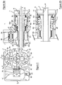
- a first example of a volumetric motor 1 of an emergency starting system comprises a casing 2 defining an internal space E1 housing two pinion teeth 3a and 3b, rotatable in opposite directions of rotation ( arrows Ra and Rb) around transmission shafts 4a and 4b.
- the housing 2 has two opposite side walls 2L and 2L 'substantially symmetrical with respect to the longitudinal plane II-II.
- a gas inlet 21 and a gas outlet 22 respectively formed on the walls 2L and 2L ', have a same axis A2 which extends substantially perpendicular to the walls 2L and 2L', halfway between the gears 3a and 3b .
- a connecting pipe 2C is fixed in the gas inlet 21 and in the heart of a pyrotechnic gas generator 5 to allow the combustion gases to be propelled into the engine 1.
- This gas generator 5 contains a propellant block 51 connection with an ignition cartridge 52.
- the casing 2 of the motor 1 and the shaft 4b of the pinion 3b extend longitudinally along the transmission shaft 4b of X'X gear shaft to receive a shaft 6 of an energy generating architecture to restart.
- the receiving shaft 6 passes through the transmission shaft 4b and is secured, out of the shaft 4b on a centrifugal cylindrical clutch 7.
- the centrifugal clutch 7 covers moving annular parts - a piston 8a, a ferrule 8b and a support 8c - for connection in rotation between the transmission shaft 4b and the clutch 7.
- the transmission shaft 4b is mounted on P1 and P2 bearings in the cylindrical extensions 20a and 20b of the housing 2, and the shaft 4a of the pinion 3a is mounted in the housing 2 by a mechanism 40 with balls and elastic blades.
- the transmission shaft 4b has at the end a conical portion 41 on which rests the ferrule 8b complementary frustoconical shape.
- annular space E2 formed in the extension 20a of the casing 2, at the periphery of the transmission shaft 4b, communicates at one end with the internal space E1 of the motor 1 and at the other end with a space radial E3 closed by the side face 8F of the piston 8a.
- the return spring 9 exerts a force sufficient to push the ferrule 8b in the direction opposite to the arrow F1 and the contact of this ferrule with the clutch 7 is broken: the shaft reception 6 is instantly disengaged.
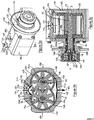
- volumetric motor of the emergency starting system is illustrated in the perspective views and in sections according to the Figures 3a to 3c .
- the volumetric motor 100 is externally as the previous volumetric motor with a housing 120 having two side walls 20L and 20L 'and a centrifugal clutch 170 mounted on the cylindrical extension 120a of the housing around a transmission shaft (see figure 3c ).
- a flange 130 is mounted on this cylindrical extension 120a via a ring 12B to allow the attachment of the motor to a casing of the architecture to be restarted.
- a gas inlet 121 appears on the so-called upper wall 12S of the casing 120.
- the housing 120 defines an internal space E11 housing - in shirts 124 - the two pinion teeth 3a and 3b of the previous example, able to rotate in opposite directions of rotation (arrows Ra and Rb) around transmission shafts 40a and 40b.
- the incoming gases (arrows F8) are separated by a deflector 125 and the jackets have openings 126 to circulate the gases in the internal space E11.
- the transmission shaft 40b has a central bore 4A which is capable of driving part of the combustion gases.
- the two opposite side walls 20L and 20L 'of the housing 120 are substantially symmetrical.
- the gases are evacuated (arrow F10) via the openings 126.
- the means of connection in rotation between the transmission shaft 40b - mounted on the bearings P3 and P4 - and the centrifugal clutch 170 is constituted by a conical piston 18 and a corresponding conical recess 18L, formed in a annular piece 19 secured to the centrifugal clutch 170.
- a helical spring 90 is arranged in a bore 180 of the piston 18, along a rod 42 coming from a stop 43 integral with the end of the transmission shaft 40b .
- the spring 90 extends between the abutment 43 and a shoulder 181 formed at the bottom of the bore 180 of the piston 18.
- a pipe 140 having a longitudinal portion 14L and a radial portion 14R, connects the gas inlet 121 of the housing 120 to the central bore 4A of the transmission shaft 40b.
- the return spring 90 exerts a force sufficient to push the piston 18 in the opposite direction of the arrow F6 and the contact of the piston with the integral piece 19 the clutch 170 is broken: a tree receiving the architecture to start, in connection with the clutch 170 is then disengaged.
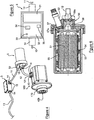
- FIG. figure 4 The overview of an exemplary emergency starting system 10 according to the invention is illustrated in FIG. figure 4 .
- This system comprises an electronic control unit 3, a pyrotechnic generator 5 and the volumetric motor 100. More precisely, the control unit 3 is connected via an electrical conduit 11 to the ignition cartridge 52 of the pyrotechnic generator 5, itself connected to the input 121 of the motor 100 via a rigid metal conduit 12.
- the control unit 3 is connected to the computer (not shown) of the architecture to start, a turbomachine in the example, via an electrical conduit 13.
- Connectors 14 fixed by screws 15 provide the connection of the ducts 11 to 13, the control unit 3, the pyrotechnic generator 5 and the volumetric motor 100.
- This engine 100 comprises a centrifugal clutch 170 in connection with the transmission shaft 40b to drive a tree of the architecture to start.
- the electronic box 3 houses a battery 31 as a source of autonomous electrical energy, and an electronic control card 32.
- This card includes a thermosensitive component 33 and a management microcontroller 34 of the battery 31, the thermosensitive component 33 and functional self-tests as well as triggering alarms of the ignition cartridge 52 of the pyrotechnic generator 5.
- the conductors 11 and 13 are mounted on the housing 3 by means of the connectors 14.
- the trip alarms include the alarms on potential fire detection, triggered by the thermosensitive component 33, and the alarms controlled by the computer based on data provided by speed sensors or temperature probes.
- the electronic card 32 includes a temperature measuring component 35 managed by the microcontroller 34 to monitor the high temperature values and allow the computer to establish the service life without degradation of operating reliability.
- FIG. 6 A sectional view of the pyrotechnic generator 5 is furthermore illustrated in figure 6 .
- This generator consists of a metal body 53 in which the propellant block 51 is arranged on wedges 54.
- An inhibitor layer 55 laterally surrounds the block 51.
- a metal cap 56 is secured to the body 53 to ensure a hermetic closure .
- the cartridge ignition 52 is screwed into a channel 57 formed in the cover 56 and closed by a nozzle 57a capable of melting above a preset temperature.
- the propellant combustion gases ignited by the cartridge 52 exit through a cap 58a of a tuned nozzle 58 in connection with the metal conduit 12 which leads to the volumetric motor 100 (see FIG. figure 4 ).
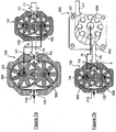
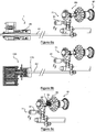
- the motors 1 or 100, the Figures 7a and 7b show in section a two-stage volumetric motor, comprising respectively two spur gear motors 101 and 102 ( figure 7a ), for example of the type of the motor 100, a roller or vane motor 200 (seen in section) and the spur gear motor 102 ( figure 7b ).
- the gases released by a pyrotechnic generator are propelled to the input 121 or 221 of the first stage (arrows F7), constituted respectively by the right-geared motor 101 ( figure 7a ) or by the roller or vane motor 200 (FIG. 1b), coupled downstream to a second stage mounted in tandem, constituted by the spur gear motor 102.
- the gases are projected at the inlet 121 (arrows F8) and at the interior (arrows F9) of the second motor 102 through the jackets 124.
- the second motor 102 is advantageously larger than the first motor 101 or 200 in order to avoid a blockage of the first engine.
- the transmission shaft 400 or central 600 of the first motor, respectively 101 or 200, is mounted in the secondary shaft 300 of the second motor 102 (arrows Ft), the transmission shaft 500 of the second motor driving the drive. architecture to restart.
- the gases exit through the outlet 122 of the second motor 102 (arrows F10).
- volumetric motor assembly 1 or 100 of the system according to the invention are illustrated in FIGS. Figures 8a to 8c .
- the receiving shaft introduced into the transmission shaft 4b of the displacement motor 1 is a shaft 61 of the accessory box 71 mounted on the HP 80 body of the turbomachine 81.
- the accessory box 71 is equipped with an electric starter 91, which is a redundant emergency starting element.
- the receiving shaft 62 of the turbomachine 81 is mounted on a bell integral with a pinion of the accessory box 71.
- the bell is the centrifugal clutch 170 of the volumetric motor 100.
- the receiving shaft introduced into the transmission shaft 4b of the positive displacement motor 1 is directly the HP shaft 82 of the HP 80 body of the turbomachine 81.
- roller rotors can be used in conjunction with guide grooves in the axial flanges.
- thermodynamic engine type architecture Stirling cycle or Ericsson or equivalent comprising a heat exchanger assembly and a variable angular wedging circuit
- the receiving shaft is the control shaft of the assembly heat exchanger and the electronic box incorporates an additional angular setting function adapted during the isochoric phases of the cycle of heating and condensation of the cycle of the thermodynamic engine.
- the number of lobes or teeth of the gears can of course vary, for example from 2 to 8 lobes (as shown), or more.
- the return means may be chosen between at least one helical spring, at least one metal blade, an electromagnet and a piston gas cartridge.
- the triggering alarms group the alarms on potential fire detection by the thermosensitive component, and alarms controlled by the computer.
- the electronic card can integrate a temperature measurement component managed by the microcontroller to monitor the high temperature values and allow the computer to establish the service life without degradation of dependability;
- the pyrotechnic gas generators may be arranged in battery in housings mounted in a barrel controlled by a cocking mechanism in connection with the inlet duct of the casing of the positive displacement motor.
Landscapes
- Engineering & Computer Science (AREA)
- Chemical & Material Sciences (AREA)
- Combustion & Propulsion (AREA)
- Mechanical Engineering (AREA)
- General Engineering & Computer Science (AREA)
- Connection Of Motors, Electrical Generators, Mechanical Devices, And The Like (AREA)
- Automotive Seat Belt Assembly (AREA)
- Control Of Eletrric Generators (AREA)
Priority Applications (1)
| Application Number | Priority Date | Filing Date | Title |
|---|---|---|---|
| PL13722505T PL2841742T3 (pl) | 2012-04-27 | 2013-04-18 | Sposób i układ do awaryjnego uruchamiania urządzenia agregatu prądotwórczego |
Applications Claiming Priority (2)
| Application Number | Priority Date | Filing Date | Title |
|---|---|---|---|
| FR1253938A FR2990004B1 (fr) | 2012-04-27 | 2012-04-27 | Procede et systeme de demarrage d'urgence d'architecture generatrice d'energie |
| PCT/FR2013/050863 WO2013160590A1 (fr) | 2012-04-27 | 2013-04-18 | Procédé et système de démarrage d'urgence d'architecture génératrice d'énergie |
Publications (2)
| Publication Number | Publication Date |
|---|---|
| EP2841742A1 EP2841742A1 (fr) | 2015-03-04 |
| EP2841742B1 true EP2841742B1 (fr) | 2016-03-30 |
Family
ID=46826641
Family Applications (1)
| Application Number | Title | Priority Date | Filing Date |
|---|---|---|---|
| EP13722505.8A Active EP2841742B1 (fr) | 2012-04-27 | 2013-04-18 | Procédé et système de démarrage d'urgence d'architecture génératrice d'énergie |
Country Status (12)
| Country | Link |
|---|---|
| US (1) | US10072580B2 (enExample) |
| EP (1) | EP2841742B1 (enExample) |
| JP (1) | JP6208216B2 (enExample) |
| KR (1) | KR102049130B1 (enExample) |
| CN (1) | CN104246181B (enExample) |
| CA (1) | CA2869361C (enExample) |
| ES (1) | ES2572093T3 (enExample) |
| FR (1) | FR2990004B1 (enExample) |
| IN (1) | IN2014DN08865A (enExample) |
| PL (1) | PL2841742T3 (enExample) |
| RU (1) | RU2621190C2 (enExample) |
| WO (1) | WO2013160590A1 (enExample) |
Families Citing this family (33)
| Publication number | Priority date | Publication date | Assignee | Title |
|---|---|---|---|---|
| FR3017417B1 (fr) * | 2014-02-10 | 2018-10-26 | Safran Helicopter Engines | Dispositif pyrotechnique pour l'entrainement d'une machine tournante |
| FR3019524B1 (fr) * | 2014-04-03 | 2017-12-08 | Turbomeca | Chaine motrice pour helicoptere incorporant un module moteur pyrotechnique d'assistance et helicoptere la comportant |
| FR3019588B1 (fr) | 2014-04-08 | 2019-06-14 | Safran Helicopter Engines | Dispositif d'assistance d'un systeme propulsif a propergol solide d'un helicoptere monomoteur, helicoptere monomoteur comprenant un tel dispositif et procede correspondant |
| FR3027346B1 (fr) * | 2014-10-20 | 2019-08-09 | Safran Helicopter Engines | Pack amovible de reactivation d'un turbomoteur, architecture d'un systeme propulsif d'un helicoptere multi-moteur equipe d'un tel pack et helicoptere correspondant |
| US10054008B2 (en) * | 2015-02-09 | 2018-08-21 | United Technologies Corporation | Turbomachine accessory gearbox bracket |
| FR3033882B1 (fr) * | 2015-03-16 | 2017-04-07 | Herakles | Generateur de gaz |
| US10508601B2 (en) | 2016-02-12 | 2019-12-17 | United Technologies Corporation | Auxiliary drive bowed rotor prevention system for a gas turbine engine |
| US9664070B1 (en) | 2016-02-12 | 2017-05-30 | United Technologies Corporation | Bowed rotor prevention system |
| US10040577B2 (en) | 2016-02-12 | 2018-08-07 | United Technologies Corporation | Modified start sequence of a gas turbine engine |
| US10125636B2 (en) | 2016-02-12 | 2018-11-13 | United Technologies Corporation | Bowed rotor prevention system using waste heat |
| US10436064B2 (en) | 2016-02-12 | 2019-10-08 | United Technologies Corporation | Bowed rotor start response damping system |
| US10174678B2 (en) | 2016-02-12 | 2019-01-08 | United Technologies Corporation | Bowed rotor start using direct temperature measurement |
| US10443505B2 (en) | 2016-02-12 | 2019-10-15 | United Technologies Corporation | Bowed rotor start mitigation in a gas turbine engine |
| US10125691B2 (en) | 2016-02-12 | 2018-11-13 | United Technologies Corporation | Bowed rotor start using a variable position starter valve |
| US10539079B2 (en) | 2016-02-12 | 2020-01-21 | United Technologies Corporation | Bowed rotor start mitigation in a gas turbine engine using aircraft-derived parameters |
| US10508567B2 (en) | 2016-02-12 | 2019-12-17 | United Technologies Corporation | Auxiliary drive bowed rotor prevention system for a gas turbine engine through an engine accessory |
| US10443507B2 (en) | 2016-02-12 | 2019-10-15 | United Technologies Corporation | Gas turbine engine bowed rotor avoidance system |
| EP3211184B1 (en) | 2016-02-29 | 2021-05-05 | Raytheon Technologies Corporation | Bowed rotor prevention system and associated method of bowed rotor prevention |
| CN107404147A (zh) * | 2016-05-20 | 2017-11-28 | 北京汽车股份有限公司 | 汽车及其应急启动发电装置 |
| US10787933B2 (en) | 2016-06-20 | 2020-09-29 | Raytheon Technologies Corporation | Low-power bowed rotor prevention and monitoring system |
| US10358936B2 (en) | 2016-07-05 | 2019-07-23 | United Technologies Corporation | Bowed rotor sensor system |
| EP3273016B1 (en) | 2016-07-21 | 2020-04-01 | United Technologies Corporation | Multi-engine coordination during gas turbine engine motoring |
| US10221774B2 (en) | 2016-07-21 | 2019-03-05 | United Technologies Corporation | Speed control during motoring of a gas turbine engine |
| US10618666B2 (en) | 2016-07-21 | 2020-04-14 | United Technologies Corporation | Pre-start motoring synchronization for multiple engines |
| US10384791B2 (en) | 2016-07-21 | 2019-08-20 | United Technologies Corporation | Cross engine coordination during gas turbine engine motoring |
| EP3273006B1 (en) | 2016-07-21 | 2019-07-03 | United Technologies Corporation | Alternating starter use during multi-engine motoring |
| US10787968B2 (en) | 2016-09-30 | 2020-09-29 | Raytheon Technologies Corporation | Gas turbine engine motoring with starter air valve manual override |
| US10443543B2 (en) | 2016-11-04 | 2019-10-15 | United Technologies Corporation | High compressor build clearance reduction |
| US10823079B2 (en) | 2016-11-29 | 2020-11-03 | Raytheon Technologies Corporation | Metered orifice for motoring of a gas turbine engine |
| US11333078B2 (en) | 2016-12-15 | 2022-05-17 | Ge Aviation Systems Llc | Air turbine starter with decoupler |
| US10823080B2 (en) | 2017-05-31 | 2020-11-03 | General Electric Company | Dual accessory gearbox |
| FR3082225B1 (fr) | 2018-06-07 | 2020-06-05 | Safran Helicopter Engines | Systeme propulsif asymetrique a recuperation de chaleur |
| US11512645B2 (en) * | 2020-03-06 | 2022-11-29 | Goodrich Corporation | Solid-propellant gas generator assemblies and methods |
Family Cites Families (12)
| Publication number | Priority date | Publication date | Assignee | Title |
|---|---|---|---|---|
| FR1104252A (fr) * | 1954-05-06 | 1955-11-17 | Snecma | Démarreur amovible destiné notamment aux moteurs d'aviation |
| US2942415A (en) * | 1954-11-29 | 1960-06-28 | Bayard Gaston | System for feeding gases into a starting turbine |
| FR1126010A (fr) * | 1955-05-09 | 1956-11-13 | Air Equipement | Perfectionnements aux démarreurs à turbine |
| FR1303228A (fr) * | 1961-08-29 | 1962-09-07 | Sundstrand A G | Démarreur pour moteurs |
| FR1334270A (fr) * | 1962-09-25 | 1963-08-02 | Cessna Aircraft Co | Moteur actionné par un fluide sous pression |
| US3633360A (en) * | 1970-01-20 | 1972-01-11 | Talley Industries | Boost starter system |
| FR2475127A1 (fr) * | 1980-02-06 | 1981-08-07 | Snecma | Generateur de gaz a variation de volume |
| US6931856B2 (en) * | 2003-09-12 | 2005-08-23 | Mes International, Inc. | Multi-spool turbogenerator system and control method |
| RU2275957C1 (ru) * | 2004-09-13 | 2006-05-10 | Российская Федерация, от имени которой выступает Государственный заказчик - Федеральное агентство по атомной энергии | Устройство для генерирования газа |
| FR2897895A1 (fr) * | 2006-02-27 | 2007-08-31 | Hispano Suiza Sa | Integration d'un demarreur/generateur dans une boite de transmission d'une turbine a gaz |
| FR2914697B1 (fr) * | 2007-04-06 | 2012-11-30 | Turbomeca | Dispositif d'assistance aux phases transitoires d'acceleration et de deceleration |
| US8148834B2 (en) * | 2009-05-19 | 2012-04-03 | General Electric Company | Aircraft engine starting/generating system and method of control |
-
2012
- 2012-04-27 FR FR1253938A patent/FR2990004B1/fr not_active Expired - Fee Related
-
2013
- 2013-04-18 JP JP2015507577A patent/JP6208216B2/ja not_active Expired - Fee Related
- 2013-04-18 IN IN8865DEN2014 patent/IN2014DN08865A/en unknown
- 2013-04-18 CA CA2869361A patent/CA2869361C/fr not_active Expired - Fee Related
- 2013-04-18 WO PCT/FR2013/050863 patent/WO2013160590A1/fr not_active Ceased
- 2013-04-18 US US14/396,235 patent/US10072580B2/en active Active
- 2013-04-18 KR KR1020147028294A patent/KR102049130B1/ko not_active Expired - Fee Related
- 2013-04-18 PL PL13722505T patent/PL2841742T3/pl unknown
- 2013-04-18 EP EP13722505.8A patent/EP2841742B1/fr active Active
- 2013-04-18 CN CN201380021227.8A patent/CN104246181B/zh not_active Expired - Fee Related
- 2013-04-18 ES ES13722505T patent/ES2572093T3/es active Active
- 2013-04-18 RU RU2014142446A patent/RU2621190C2/ru active
Also Published As
| Publication number | Publication date |
|---|---|
| IN2014DN08865A (enExample) | 2015-05-22 |
| RU2014142446A (ru) | 2016-06-20 |
| ES2572093T3 (es) | 2016-05-30 |
| RU2621190C2 (ru) | 2017-06-01 |
| US20150128592A1 (en) | 2015-05-14 |
| CN104246181A (zh) | 2014-12-24 |
| KR102049130B1 (ko) | 2019-11-26 |
| KR20150003189A (ko) | 2015-01-08 |
| CA2869361C (fr) | 2020-06-30 |
| JP6208216B2 (ja) | 2017-10-04 |
| JP2015520821A (ja) | 2015-07-23 |
| PL2841742T3 (pl) | 2016-08-31 |
| CA2869361A1 (fr) | 2013-10-31 |
| CN104246181B (zh) | 2016-06-22 |
| WO2013160590A1 (fr) | 2013-10-31 |
| FR2990004B1 (fr) | 2014-04-18 |
| FR2990004A1 (fr) | 2013-11-01 |
| US10072580B2 (en) | 2018-09-11 |
| EP2841742A1 (fr) | 2015-03-04 |
Similar Documents
| Publication | Publication Date | Title |
|---|---|---|
| EP2841742B1 (fr) | Procédé et système de démarrage d'urgence d'architecture génératrice d'énergie | |
| EP3047117B1 (fr) | Système et procédé de démarrage d'urgence de turbomachines d'aéronef | |
| EP3864299B1 (fr) | Turbomachine comprenant un rotor portant des pales a calage variable | |
| CA2389780C (fr) | Dispositif de secours au rallumage d'un turboreacteur en auto-rotation | |
| EP3513050B1 (fr) | Dispositif de rupture d'arbre d'un générateur électrique | |
| EP3129619B1 (fr) | Dispositif d'assistance à propergol solide d'un système propulsif d'un hélicoptère monomoteur, hélicoptère monomoteur comprenant un tel dispositif | |
| EP4304932B1 (fr) | Dispositif de calage de pas de pales pour turbomachine et turbomachine le comportant | |
| EP3999730B1 (fr) | Réducteur à train épicycloïdal pour une turbomachine | |
| EP4237671B1 (fr) | Turbogénérateur à turbine libre comprenant une machine électrique réversible couplée à la turbine libre | |
| EP4486650A1 (fr) | Ensemble propulsif ameliore pour aeronef hybride multi moteurs | |
| EP4493807A1 (fr) | Turbomachine amelioree pour aeronef hybride | |
| EP1541833A1 (fr) | Générateur de gaz et turboréacteur équipé d'un tel générateur pour le démarrage | |
| EP3448751B1 (fr) | Systeme auxiliaire d'entrainement d'un arbre d'un systeme propulsif d'un helicoptere | |
| FR3087423A1 (fr) | Systeme de couplage/decouplage de boitiers d'accessoires |
Legal Events
| Date | Code | Title | Description |
|---|---|---|---|
| PUAI | Public reference made under article 153(3) epc to a published international application that has entered the european phase |
Free format text: ORIGINAL CODE: 0009012 |
|
| 17P | Request for examination filed |
Effective date: 20141113 |
|
| AK | Designated contracting states |
Kind code of ref document: A1 Designated state(s): AL AT BE BG CH CY CZ DE DK EE ES FI FR GB GR HR HU IE IS IT LI LT LU LV MC MK MT NL NO PL PT RO RS SE SI SK SM TR |
|
| AX | Request for extension of the european patent |
Extension state: BA ME |
|
| DAX | Request for extension of the european patent (deleted) | ||
| GRAP | Despatch of communication of intention to grant a patent |
Free format text: ORIGINAL CODE: EPIDOSNIGR1 |
|
| INTG | Intention to grant announced |
Effective date: 20150914 |
|
| GRAS | Grant fee paid |
Free format text: ORIGINAL CODE: EPIDOSNIGR3 |
|
| INTG | Intention to grant announced |
Effective date: 20160112 |
|
| GRAA | (expected) grant |
Free format text: ORIGINAL CODE: 0009210 |
|
| AK | Designated contracting states |
Kind code of ref document: B1 Designated state(s): AL AT BE BG CH CY CZ DE DK EE ES FI FR GB GR HR HU IE IS IT LI LT LU LV MC MK MT NL NO PL PT RO RS SE SI SK SM TR |
|
| REG | Reference to a national code |
Ref country code: GB Ref legal event code: FG4D Free format text: NOT ENGLISH |
|
| REG | Reference to a national code |
Ref country code: CH Ref legal event code: EP |
|
| REG | Reference to a national code |
Ref country code: FR Ref legal event code: PLFP Year of fee payment: 4 |
|
| REG | Reference to a national code |
Ref country code: AT Ref legal event code: REF Ref document number: 785671 Country of ref document: AT Kind code of ref document: T Effective date: 20160415 |
|
| REG | Reference to a national code |
Ref country code: IE Ref legal event code: FG4D Free format text: LANGUAGE OF EP DOCUMENT: FRENCH |
|
| REG | Reference to a national code |
Ref country code: DE Ref legal event code: R096 Ref document number: 602013005985 Country of ref document: DE |
|
| REG | Reference to a national code |
Ref country code: ES Ref legal event code: FG2A Ref document number: 2572093 Country of ref document: ES Kind code of ref document: T3 Effective date: 20160530 |
|
| REG | Reference to a national code |
Ref country code: SE Ref legal event code: TRGR |
|
| REG | Reference to a national code |
Ref country code: LT Ref legal event code: MG4D |
|
| PG25 | Lapsed in a contracting state [announced via postgrant information from national office to epo] |
Ref country code: FI Free format text: LAPSE BECAUSE OF FAILURE TO SUBMIT A TRANSLATION OF THE DESCRIPTION OR TO PAY THE FEE WITHIN THE PRESCRIBED TIME-LIMIT Effective date: 20160330 Ref country code: HR Free format text: LAPSE BECAUSE OF FAILURE TO SUBMIT A TRANSLATION OF THE DESCRIPTION OR TO PAY THE FEE WITHIN THE PRESCRIBED TIME-LIMIT Effective date: 20160330 Ref country code: NO Free format text: LAPSE BECAUSE OF FAILURE TO SUBMIT A TRANSLATION OF THE DESCRIPTION OR TO PAY THE FEE WITHIN THE PRESCRIBED TIME-LIMIT Effective date: 20160630 Ref country code: GR Free format text: LAPSE BECAUSE OF FAILURE TO SUBMIT A TRANSLATION OF THE DESCRIPTION OR TO PAY THE FEE WITHIN THE PRESCRIBED TIME-LIMIT Effective date: 20160701 |
|
| REG | Reference to a national code |
Ref country code: NL Ref legal event code: MP Effective date: 20160330 |
|
| REG | Reference to a national code |
Ref country code: AT Ref legal event code: MK05 Ref document number: 785671 Country of ref document: AT Kind code of ref document: T Effective date: 20160330 |
|
| PG25 | Lapsed in a contracting state [announced via postgrant information from national office to epo] |
Ref country code: BE Free format text: LAPSE BECAUSE OF NON-PAYMENT OF DUE FEES Effective date: 20160430 Ref country code: RS Free format text: LAPSE BECAUSE OF FAILURE TO SUBMIT A TRANSLATION OF THE DESCRIPTION OR TO PAY THE FEE WITHIN THE PRESCRIBED TIME-LIMIT Effective date: 20160330 Ref country code: LV Free format text: LAPSE BECAUSE OF FAILURE TO SUBMIT A TRANSLATION OF THE DESCRIPTION OR TO PAY THE FEE WITHIN THE PRESCRIBED TIME-LIMIT Effective date: 20160330 Ref country code: LT Free format text: LAPSE BECAUSE OF FAILURE TO SUBMIT A TRANSLATION OF THE DESCRIPTION OR TO PAY THE FEE WITHIN THE PRESCRIBED TIME-LIMIT Effective date: 20160330 |
|
| PG25 | Lapsed in a contracting state [announced via postgrant information from national office to epo] |
Ref country code: NL Free format text: LAPSE BECAUSE OF FAILURE TO SUBMIT A TRANSLATION OF THE DESCRIPTION OR TO PAY THE FEE WITHIN THE PRESCRIBED TIME-LIMIT Effective date: 20160330 |
|
| PG25 | Lapsed in a contracting state [announced via postgrant information from national office to epo] |
Ref country code: EE Free format text: LAPSE BECAUSE OF FAILURE TO SUBMIT A TRANSLATION OF THE DESCRIPTION OR TO PAY THE FEE WITHIN THE PRESCRIBED TIME-LIMIT Effective date: 20160330 Ref country code: IS Free format text: LAPSE BECAUSE OF FAILURE TO SUBMIT A TRANSLATION OF THE DESCRIPTION OR TO PAY THE FEE WITHIN THE PRESCRIBED TIME-LIMIT Effective date: 20160730 |
|
| PG25 | Lapsed in a contracting state [announced via postgrant information from national office to epo] |
Ref country code: RO Free format text: LAPSE BECAUSE OF FAILURE TO SUBMIT A TRANSLATION OF THE DESCRIPTION OR TO PAY THE FEE WITHIN THE PRESCRIBED TIME-LIMIT Effective date: 20160330 Ref country code: PT Free format text: LAPSE BECAUSE OF FAILURE TO SUBMIT A TRANSLATION OF THE DESCRIPTION OR TO PAY THE FEE WITHIN THE PRESCRIBED TIME-LIMIT Effective date: 20160801 Ref country code: SK Free format text: LAPSE BECAUSE OF FAILURE TO SUBMIT A TRANSLATION OF THE DESCRIPTION OR TO PAY THE FEE WITHIN THE PRESCRIBED TIME-LIMIT Effective date: 20160330 Ref country code: SM Free format text: LAPSE BECAUSE OF FAILURE TO SUBMIT A TRANSLATION OF THE DESCRIPTION OR TO PAY THE FEE WITHIN THE PRESCRIBED TIME-LIMIT Effective date: 20160330 Ref country code: AT Free format text: LAPSE BECAUSE OF FAILURE TO SUBMIT A TRANSLATION OF THE DESCRIPTION OR TO PAY THE FEE WITHIN THE PRESCRIBED TIME-LIMIT Effective date: 20160330 |
|
| REG | Reference to a national code |
Ref country code: CH Ref legal event code: PL |
|
| REG | Reference to a national code |
Ref country code: DE Ref legal event code: R097 Ref document number: 602013005985 Country of ref document: DE |
|
| RAP2 | Party data changed (patent owner data changed or rights of a patent transferred) |
Owner name: SAFRAN HELICOPTER ENGINES |
|
| REG | Reference to a national code |
Ref country code: IE Ref legal event code: MM4A |
|
| PG25 | Lapsed in a contracting state [announced via postgrant information from national office to epo] |
Ref country code: LI Free format text: LAPSE BECAUSE OF NON-PAYMENT OF DUE FEES Effective date: 20160430 Ref country code: DK Free format text: LAPSE BECAUSE OF FAILURE TO SUBMIT A TRANSLATION OF THE DESCRIPTION OR TO PAY THE FEE WITHIN THE PRESCRIBED TIME-LIMIT Effective date: 20160330 Ref country code: CH Free format text: LAPSE BECAUSE OF NON-PAYMENT OF DUE FEES Effective date: 20160430 |
|
| PLBE | No opposition filed within time limit |
Free format text: ORIGINAL CODE: 0009261 |
|
| STAA | Information on the status of an ep patent application or granted ep patent |
Free format text: STATUS: NO OPPOSITION FILED WITHIN TIME LIMIT |
|
| 26N | No opposition filed |
Effective date: 20170103 |
|
| REG | Reference to a national code |
Ref country code: FR Ref legal event code: PLFP Year of fee payment: 5 |
|
| PG25 | Lapsed in a contracting state [announced via postgrant information from national office to epo] |
Ref country code: SI Free format text: LAPSE BECAUSE OF FAILURE TO SUBMIT A TRANSLATION OF THE DESCRIPTION OR TO PAY THE FEE WITHIN THE PRESCRIBED TIME-LIMIT Effective date: 20160330 Ref country code: IE Free format text: LAPSE BECAUSE OF NON-PAYMENT OF DUE FEES Effective date: 20160418 |
|
| REG | Reference to a national code |
Ref country code: FR Ref legal event code: CD Owner name: SAFRAN HELICOPTER ENGINES, FR Effective date: 20170727 |
|
| REG | Reference to a national code |
Ref country code: FR Ref legal event code: PLFP Year of fee payment: 6 |
|
| PG25 | Lapsed in a contracting state [announced via postgrant information from national office to epo] |
Ref country code: HU Free format text: LAPSE BECAUSE OF FAILURE TO SUBMIT A TRANSLATION OF THE DESCRIPTION OR TO PAY THE FEE WITHIN THE PRESCRIBED TIME-LIMIT; INVALID AB INITIO Effective date: 20130418 |
|
| PG25 | Lapsed in a contracting state [announced via postgrant information from national office to epo] |
Ref country code: MK Free format text: LAPSE BECAUSE OF FAILURE TO SUBMIT A TRANSLATION OF THE DESCRIPTION OR TO PAY THE FEE WITHIN THE PRESCRIBED TIME-LIMIT Effective date: 20160330 Ref country code: CY Free format text: LAPSE BECAUSE OF FAILURE TO SUBMIT A TRANSLATION OF THE DESCRIPTION OR TO PAY THE FEE WITHIN THE PRESCRIBED TIME-LIMIT Effective date: 20160330 Ref country code: MC Free format text: LAPSE BECAUSE OF FAILURE TO SUBMIT A TRANSLATION OF THE DESCRIPTION OR TO PAY THE FEE WITHIN THE PRESCRIBED TIME-LIMIT Effective date: 20160330 Ref country code: MT Free format text: LAPSE BECAUSE OF FAILURE TO SUBMIT A TRANSLATION OF THE DESCRIPTION OR TO PAY THE FEE WITHIN THE PRESCRIBED TIME-LIMIT Effective date: 20160330 Ref country code: LU Free format text: LAPSE BECAUSE OF NON-PAYMENT OF DUE FEES Effective date: 20160418 |
|
| PG25 | Lapsed in a contracting state [announced via postgrant information from national office to epo] |
Ref country code: BG Free format text: LAPSE BECAUSE OF FAILURE TO SUBMIT A TRANSLATION OF THE DESCRIPTION OR TO PAY THE FEE WITHIN THE PRESCRIBED TIME-LIMIT Effective date: 20160330 |
|
| PG25 | Lapsed in a contracting state [announced via postgrant information from national office to epo] |
Ref country code: TR Free format text: LAPSE BECAUSE OF FAILURE TO SUBMIT A TRANSLATION OF THE DESCRIPTION OR TO PAY THE FEE WITHIN THE PRESCRIBED TIME-LIMIT Effective date: 20160330 Ref country code: AL Free format text: LAPSE BECAUSE OF FAILURE TO SUBMIT A TRANSLATION OF THE DESCRIPTION OR TO PAY THE FEE WITHIN THE PRESCRIBED TIME-LIMIT Effective date: 20160330 |
|
| PGFP | Annual fee paid to national office [announced via postgrant information from national office to epo] |
Ref country code: CZ Payment date: 20210326 Year of fee payment: 9 Ref country code: IT Payment date: 20210323 Year of fee payment: 9 |
|
| PGFP | Annual fee paid to national office [announced via postgrant information from national office to epo] |
Ref country code: PL Payment date: 20210325 Year of fee payment: 9 Ref country code: GB Payment date: 20210324 Year of fee payment: 9 Ref country code: SE Payment date: 20210329 Year of fee payment: 9 |
|
| PGFP | Annual fee paid to national office [announced via postgrant information from national office to epo] |
Ref country code: DE Payment date: 20210323 Year of fee payment: 9 |
|
| PGFP | Annual fee paid to national office [announced via postgrant information from national office to epo] |
Ref country code: ES Payment date: 20210503 Year of fee payment: 9 |
|
| REG | Reference to a national code |
Ref country code: DE Ref legal event code: R119 Ref document number: 602013005985 Country of ref document: DE |
|
| REG | Reference to a national code |
Ref country code: SE Ref legal event code: EUG |
|
| GBPC | Gb: european patent ceased through non-payment of renewal fee |
Effective date: 20220418 |
|
| PG25 | Lapsed in a contracting state [announced via postgrant information from national office to epo] |
Ref country code: SE Free format text: LAPSE BECAUSE OF NON-PAYMENT OF DUE FEES Effective date: 20220419 Ref country code: GB Free format text: LAPSE BECAUSE OF NON-PAYMENT OF DUE FEES Effective date: 20220418 Ref country code: DE Free format text: LAPSE BECAUSE OF NON-PAYMENT OF DUE FEES Effective date: 20221103 Ref country code: CZ Free format text: LAPSE BECAUSE OF NON-PAYMENT OF DUE FEES Effective date: 20220418 |
|
| PG25 | Lapsed in a contracting state [announced via postgrant information from national office to epo] |
Ref country code: IT Free format text: LAPSE BECAUSE OF NON-PAYMENT OF DUE FEES Effective date: 20220418 |
|
| REG | Reference to a national code |
Ref country code: ES Ref legal event code: FD2A Effective date: 20230628 |
|
| PG25 | Lapsed in a contracting state [announced via postgrant information from national office to epo] |
Ref country code: ES Free format text: LAPSE BECAUSE OF NON-PAYMENT OF DUE FEES Effective date: 20220419 |
|
| PG25 | Lapsed in a contracting state [announced via postgrant information from national office to epo] |
Ref country code: PL Free format text: LAPSE BECAUSE OF NON-PAYMENT OF DUE FEES Effective date: 20220418 |
|
| PGFP | Annual fee paid to national office [announced via postgrant information from national office to epo] |
Ref country code: FR Payment date: 20250428 Year of fee payment: 13 |