EP2841742B1 - Method and system for an emergency start of a power generator - Google Patents
Method and system for an emergency start of a power generator Download PDFInfo
- Publication number
- EP2841742B1 EP2841742B1 EP13722505.8A EP13722505A EP2841742B1 EP 2841742 B1 EP2841742 B1 EP 2841742B1 EP 13722505 A EP13722505 A EP 13722505A EP 2841742 B1 EP2841742 B1 EP 2841742B1
- Authority
- EP
- European Patent Office
- Prior art keywords
- motor
- shaft
- emergency start
- gases
- positive displacement
- Prior art date
- Legal status (The legal status is an assumption and is not a legal conclusion. Google has not performed a legal analysis and makes no representation as to the accuracy of the status listed.)
- Active
Links
Images
Classifications
-
- F—MECHANICAL ENGINEERING; LIGHTING; HEATING; WEAPONS; BLASTING
- F02—COMBUSTION ENGINES; HOT-GAS OR COMBUSTION-PRODUCT ENGINE PLANTS
- F02C—GAS-TURBINE PLANTS; AIR INTAKES FOR JET-PROPULSION PLANTS; CONTROLLING FUEL SUPPLY IN AIR-BREATHING JET-PROPULSION PLANTS
- F02C7/00—Features, components parts, details or accessories, not provided for in, or of interest apart form groups F02C1/00 - F02C6/00; Air intakes for jet-propulsion plants
- F02C7/26—Starting; Ignition
- F02C7/268—Starting drives for the rotor, acting directly on the rotor of the gas turbine to be started
- F02C7/27—Fluid drives
- F02C7/272—Fluid drives generated by cartridges
-
- F—MECHANICAL ENGINEERING; LIGHTING; HEATING; WEAPONS; BLASTING
- F02—COMBUSTION ENGINES; HOT-GAS OR COMBUSTION-PRODUCT ENGINE PLANTS
- F02C—GAS-TURBINE PLANTS; AIR INTAKES FOR JET-PROPULSION PLANTS; CONTROLLING FUEL SUPPLY IN AIR-BREATHING JET-PROPULSION PLANTS
- F02C7/00—Features, components parts, details or accessories, not provided for in, or of interest apart form groups F02C1/00 - F02C6/00; Air intakes for jet-propulsion plants
- F02C7/26—Starting; Ignition
- F02C7/268—Starting drives for the rotor, acting directly on the rotor of the gas turbine to be started
- F02C7/275—Mechanical drives
-
- F—MECHANICAL ENGINEERING; LIGHTING; HEATING; WEAPONS; BLASTING
- F02—COMBUSTION ENGINES; HOT-GAS OR COMBUSTION-PRODUCT ENGINE PLANTS
- F02N—STARTING OF COMBUSTION ENGINES; STARTING AIDS FOR SUCH ENGINES, NOT OTHERWISE PROVIDED FOR
- F02N13/00—Starting of engines, or driving of starting apparatus by use of explosives, e.g. stored in cartridges
-
- F—MECHANICAL ENGINEERING; LIGHTING; HEATING; WEAPONS; BLASTING
- F02—COMBUSTION ENGINES; HOT-GAS OR COMBUSTION-PRODUCT ENGINE PLANTS
- F02N—STARTING OF COMBUSTION ENGINES; STARTING AIDS FOR SUCH ENGINES, NOT OTHERWISE PROVIDED FOR
- F02N15/00—Other power-operated starting apparatus; Component parts, details, or accessories, not provided for in, or of interest apart from groups F02N5/00 - F02N13/00
- F02N15/10—Safety devices not otherwise provided for
-
- Y—GENERAL TAGGING OF NEW TECHNOLOGICAL DEVELOPMENTS; GENERAL TAGGING OF CROSS-SECTIONAL TECHNOLOGIES SPANNING OVER SEVERAL SECTIONS OF THE IPC; TECHNICAL SUBJECTS COVERED BY FORMER USPC CROSS-REFERENCE ART COLLECTIONS [XRACs] AND DIGESTS
- Y02—TECHNOLOGIES OR APPLICATIONS FOR MITIGATION OR ADAPTATION AGAINST CLIMATE CHANGE
- Y02T—CLIMATE CHANGE MITIGATION TECHNOLOGIES RELATED TO TRANSPORTATION
- Y02T50/00—Aeronautics or air transport
- Y02T50/60—Efficient propulsion technologies, e.g. for aircraft
Definitions
- the invention relates to a method and an emergency starting system of an energy generating architecture in critical situations where the dedicated motor is stopped or insufficient to meet the needs.
- Pneumatic and hydraulic starters have disadvantages related to their mass and their size. In addition, periodic checks of envelopes and replacement of pressure vessels are necessary.
- the restart in flight of a turbine engine is provided by an electric starter powered by the onboard network or a backup battery.
- this technology is expensive: presence of permanent magnets, transverse flux, planar architecture, etc.
- it requires an electronic device for monitoring the load and a periodic change of battery.
- emergency situations that may arise in the applications envisaged above, require to have reaction time of the order of a few seconds, in particular two to three seconds, or even less than the second, so ensure an emergency start-up or restart with a sufficient margin of safety.
- the invention aims to provide emergency starters allowing a reactivity of this order of magnitude, namely a few seconds, without the disadvantages associated with the mass and size of the hydraulic or emergency starters mentioned above .
- the present invention proposes to couple an instantaneous thrust of pyrotechnic type gas with a volumetric transmission generator in connection with automatic coupling / decoupling on the architecture to start.
- the subject of the present invention is an emergency starting method of an energy generating architecture in which, an emergency starting situation of the architecture being detected, at least one pyrotechnic gas combustion generator. is triggered. Gases under pressure are then generated by this combustion and directly injected into a volumetric gear motor preferably straight. Part of these gases then drive the gears of the engine in rotation and, simultaneously, the remaining part of the gas projects, against a restoring force, a coupling connection between the engine and the architecture.
- the connector ensures the transmission of energy by rotational drive of a volumetric motor gear shaft on a tree receiving the architecture. When the thrust becomes lower than the restoring force, it automatically pushes back the connectors and the architecture is disconnected from the volumetric motor.
- the invention also relates to an emergency start system of an energy generating architecture capable of implementing the above method.
- This system comprises at least one pyrotechnic gas generator connected to an electric initiator which is itself connected to a computer, a volumetric motor comprising a housing defining an internal space housing spur gears, the pyrotechnic gas generator being coupled to the motor by an input crankcase.
- the motor comprises a connection means, adapted to move at one end of a transmission shaft centered on a gear axis of the positive displacement motor, so as to be able to couple this transmission shaft to a shaft receiving the architecture via a clutch. centrifugal.
- a return means arranged in abutment is able to exert a restoring force against the pressure exerted on the connection means.
- each volumetric motor is dimensioned to be able to provide a power of the order of 40 kW for about 2.5 seconds for each injection of pyrotechnic gas, with a reaction time of the order of 0.5 seconds.
- the system is dimensioned and qualified to allow a nominal use in the temperature range of -30 to + 50 ° C, which range can extend to the qualification limit temperatures of surrounding equipment, for example the order of 135 ° C for the extreme environments mentioned above.
- the ambient operating pressure is between about 60 and 110 kPa.
- thermodynamic engine cycle
- cross-section refers to a view in a plane perpendicular to the so-called longitudinal axis of the motors which extend mainly along such an axis.
- longitudinal section designates a sectional view along said longitudinal axis.
- qualifiers “upper” or “lower” refer to relative locations of wall or face of a device disposed in the standard position of use.
- identical reference signs refer to identical elements as described in the corresponding passages.
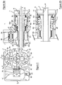
- a first example of a volumetric motor 1 of an emergency starting system comprises a casing 2 defining an internal space E1 housing two pinion teeth 3a and 3b, rotatable in opposite directions of rotation ( arrows Ra and Rb) around transmission shafts 4a and 4b.
- the housing 2 has two opposite side walls 2L and 2L 'substantially symmetrical with respect to the longitudinal plane II-II.
- a gas inlet 21 and a gas outlet 22 respectively formed on the walls 2L and 2L ', have a same axis A2 which extends substantially perpendicular to the walls 2L and 2L', halfway between the gears 3a and 3b .
- a connecting pipe 2C is fixed in the gas inlet 21 and in the heart of a pyrotechnic gas generator 5 to allow the combustion gases to be propelled into the engine 1.
- This gas generator 5 contains a propellant block 51 connection with an ignition cartridge 52.
- the casing 2 of the motor 1 and the shaft 4b of the pinion 3b extend longitudinally along the transmission shaft 4b of X'X gear shaft to receive a shaft 6 of an energy generating architecture to restart.
- the receiving shaft 6 passes through the transmission shaft 4b and is secured, out of the shaft 4b on a centrifugal cylindrical clutch 7.
- the centrifugal clutch 7 covers moving annular parts - a piston 8a, a ferrule 8b and a support 8c - for connection in rotation between the transmission shaft 4b and the clutch 7.
- the transmission shaft 4b is mounted on P1 and P2 bearings in the cylindrical extensions 20a and 20b of the housing 2, and the shaft 4a of the pinion 3a is mounted in the housing 2 by a mechanism 40 with balls and elastic blades.
- the transmission shaft 4b has at the end a conical portion 41 on which rests the ferrule 8b complementary frustoconical shape.
- annular space E2 formed in the extension 20a of the casing 2, at the periphery of the transmission shaft 4b, communicates at one end with the internal space E1 of the motor 1 and at the other end with a space radial E3 closed by the side face 8F of the piston 8a.
- the return spring 9 exerts a force sufficient to push the ferrule 8b in the direction opposite to the arrow F1 and the contact of this ferrule with the clutch 7 is broken: the shaft reception 6 is instantly disengaged.
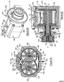
- volumetric motor of the emergency starting system is illustrated in the perspective views and in sections according to the Figures 3a to 3c .
- the volumetric motor 100 is externally as the previous volumetric motor with a housing 120 having two side walls 20L and 20L 'and a centrifugal clutch 170 mounted on the cylindrical extension 120a of the housing around a transmission shaft (see figure 3c ).
- a flange 130 is mounted on this cylindrical extension 120a via a ring 12B to allow the attachment of the motor to a casing of the architecture to be restarted.
- a gas inlet 121 appears on the so-called upper wall 12S of the casing 120.
- the housing 120 defines an internal space E11 housing - in shirts 124 - the two pinion teeth 3a and 3b of the previous example, able to rotate in opposite directions of rotation (arrows Ra and Rb) around transmission shafts 40a and 40b.
- the incoming gases (arrows F8) are separated by a deflector 125 and the jackets have openings 126 to circulate the gases in the internal space E11.
- the transmission shaft 40b has a central bore 4A which is capable of driving part of the combustion gases.
- the two opposite side walls 20L and 20L 'of the housing 120 are substantially symmetrical.
- the gases are evacuated (arrow F10) via the openings 126.
- the means of connection in rotation between the transmission shaft 40b - mounted on the bearings P3 and P4 - and the centrifugal clutch 170 is constituted by a conical piston 18 and a corresponding conical recess 18L, formed in a annular piece 19 secured to the centrifugal clutch 170.
- a helical spring 90 is arranged in a bore 180 of the piston 18, along a rod 42 coming from a stop 43 integral with the end of the transmission shaft 40b .
- the spring 90 extends between the abutment 43 and a shoulder 181 formed at the bottom of the bore 180 of the piston 18.
- a pipe 140 having a longitudinal portion 14L and a radial portion 14R, connects the gas inlet 121 of the housing 120 to the central bore 4A of the transmission shaft 40b.
- the return spring 90 exerts a force sufficient to push the piston 18 in the opposite direction of the arrow F6 and the contact of the piston with the integral piece 19 the clutch 170 is broken: a tree receiving the architecture to start, in connection with the clutch 170 is then disengaged.
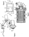
- FIG. figure 4 The overview of an exemplary emergency starting system 10 according to the invention is illustrated in FIG. figure 4 .
- This system comprises an electronic control unit 3, a pyrotechnic generator 5 and the volumetric motor 100. More precisely, the control unit 3 is connected via an electrical conduit 11 to the ignition cartridge 52 of the pyrotechnic generator 5, itself connected to the input 121 of the motor 100 via a rigid metal conduit 12.
- the control unit 3 is connected to the computer (not shown) of the architecture to start, a turbomachine in the example, via an electrical conduit 13.
- Connectors 14 fixed by screws 15 provide the connection of the ducts 11 to 13, the control unit 3, the pyrotechnic generator 5 and the volumetric motor 100.
- This engine 100 comprises a centrifugal clutch 170 in connection with the transmission shaft 40b to drive a tree of the architecture to start.
- the electronic box 3 houses a battery 31 as a source of autonomous electrical energy, and an electronic control card 32.
- This card includes a thermosensitive component 33 and a management microcontroller 34 of the battery 31, the thermosensitive component 33 and functional self-tests as well as triggering alarms of the ignition cartridge 52 of the pyrotechnic generator 5.
- the conductors 11 and 13 are mounted on the housing 3 by means of the connectors 14.
- the trip alarms include the alarms on potential fire detection, triggered by the thermosensitive component 33, and the alarms controlled by the computer based on data provided by speed sensors or temperature probes.
- the electronic card 32 includes a temperature measuring component 35 managed by the microcontroller 34 to monitor the high temperature values and allow the computer to establish the service life without degradation of operating reliability.
- FIG. 6 A sectional view of the pyrotechnic generator 5 is furthermore illustrated in figure 6 .
- This generator consists of a metal body 53 in which the propellant block 51 is arranged on wedges 54.
- An inhibitor layer 55 laterally surrounds the block 51.
- a metal cap 56 is secured to the body 53 to ensure a hermetic closure .
- the cartridge ignition 52 is screwed into a channel 57 formed in the cover 56 and closed by a nozzle 57a capable of melting above a preset temperature.
- the propellant combustion gases ignited by the cartridge 52 exit through a cap 58a of a tuned nozzle 58 in connection with the metal conduit 12 which leads to the volumetric motor 100 (see FIG. figure 4 ).
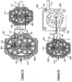
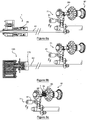
- the motors 1 or 100, the Figures 7a and 7b show in section a two-stage volumetric motor, comprising respectively two spur gear motors 101 and 102 ( figure 7a ), for example of the type of the motor 100, a roller or vane motor 200 (seen in section) and the spur gear motor 102 ( figure 7b ).
- the gases released by a pyrotechnic generator are propelled to the input 121 or 221 of the first stage (arrows F7), constituted respectively by the right-geared motor 101 ( figure 7a ) or by the roller or vane motor 200 (FIG. 1b), coupled downstream to a second stage mounted in tandem, constituted by the spur gear motor 102.
- the gases are projected at the inlet 121 (arrows F8) and at the interior (arrows F9) of the second motor 102 through the jackets 124.
- the second motor 102 is advantageously larger than the first motor 101 or 200 in order to avoid a blockage of the first engine.
- the transmission shaft 400 or central 600 of the first motor, respectively 101 or 200, is mounted in the secondary shaft 300 of the second motor 102 (arrows Ft), the transmission shaft 500 of the second motor driving the drive. architecture to restart.
- the gases exit through the outlet 122 of the second motor 102 (arrows F10).
- volumetric motor assembly 1 or 100 of the system according to the invention are illustrated in FIGS. Figures 8a to 8c .
- the receiving shaft introduced into the transmission shaft 4b of the displacement motor 1 is a shaft 61 of the accessory box 71 mounted on the HP 80 body of the turbomachine 81.
- the accessory box 71 is equipped with an electric starter 91, which is a redundant emergency starting element.
- the receiving shaft 62 of the turbomachine 81 is mounted on a bell integral with a pinion of the accessory box 71.
- the bell is the centrifugal clutch 170 of the volumetric motor 100.
- the receiving shaft introduced into the transmission shaft 4b of the positive displacement motor 1 is directly the HP shaft 82 of the HP 80 body of the turbomachine 81.
- roller rotors can be used in conjunction with guide grooves in the axial flanges.
- thermodynamic engine type architecture Stirling cycle or Ericsson or equivalent comprising a heat exchanger assembly and a variable angular wedging circuit
- the receiving shaft is the control shaft of the assembly heat exchanger and the electronic box incorporates an additional angular setting function adapted during the isochoric phases of the cycle of heating and condensation of the cycle of the thermodynamic engine.
- the number of lobes or teeth of the gears can of course vary, for example from 2 to 8 lobes (as shown), or more.
- the return means may be chosen between at least one helical spring, at least one metal blade, an electromagnet and a piston gas cartridge.
- the triggering alarms group the alarms on potential fire detection by the thermosensitive component, and alarms controlled by the computer.
- the electronic card can integrate a temperature measurement component managed by the microcontroller to monitor the high temperature values and allow the computer to establish the service life without degradation of dependability;
- the pyrotechnic gas generators may be arranged in battery in housings mounted in a barrel controlled by a cocking mechanism in connection with the inlet duct of the casing of the positive displacement motor.
Description
L'invention concerne un procédé et un Système de démarrage d'urgence d'une architecture génératrice d'énergie dans des situations critiques où la motorisation dédiée est arrêtée ou insuffisante pour faire face aux besoins.The invention relates to a method and an emergency starting system of an energy generating architecture in critical situations where the dedicated motor is stopped or insufficient to meet the needs.
L'invention s'applique dans le cadre d'une assistance ou d'un ultime secours pour déclencher l'activation ou la réactivation de génération d'énergie dans différents domaines technologiques :
- en motorisation aéronautique pour les turbines à gaz d'avion ou d'hélicoptère ;
- en génie électrique pour les disjoncteurs ultra-limiteurs d'infrastructures de production et de transport d'énergie électrique, en particulier dans les sous-marins ;
- en forage ou en immersion maritime pour des vis de vanne maîtresse, des robots, etc. ; domaine dénommé « Oil & Gas » ;
- en milieux extrêmes (hôpital, centrales nucléaires, aéroports, centres serveurs) pour des générateurs, pompes, vannes de sécurité, etc. ;
- en génération thermodynamique d'une architecture de générateur de type Stirling ou Ericsson ;
- en génération hydraulique ou pneumatique pour manoeuvrer des masses (vérins de train d'atterrissage, engins d'élévation, etc.).
- in aircraft engines for aircraft or helicopter gas turbines;
- in electrical engineering for ultra-limiting circuit breakers for the production and transmission of electrical energy, particularly in submarines;
- in drilling or marine immersion for master valve screws, robots, etc. ; area called "Oil &Gas";
- in extreme environments (hospitals, nuclear power plants, airports, server centers) for generators, pumps, safety valves, etc. ;
- in thermodynamic generation of a Stirling or Ericsson type generator architecture;
- in hydraulic or pneumatic generation for maneuvering masses (landing gear cylinders, elevating machines, etc.).
En particulier dans le cas d'un hélicoptère bimoteur, des situations critiques peuvent surgir lorsque l'un des moteurs est volontairement éteint. Ce mode est en effet recommandé pour minimiser la consommation pendant les phases de recherche et de croisière d'une mission. Dans ce contexte, deux situations exceptionnelles peuvent survenir qui nécessitent alors un redémarrage d'urgence du moteur éteint :
- le seul moteur actif s'arrête ou ralentit sensiblement pour une raison inconnue;
- les conditions de vol subissent une dégradation imprévue qui nécessite un retour en mode bimoteur (hauteur de vol insuffisante par exemple).
- the only active motor stops or slows down substantially for an unknown reason;
- the flight conditions undergo an unforeseen degradation which requires a return in twin engine mode (insufficient flight height for example).
Le redémarrage d'une turbine à gaz peut être réalisé, actuellement, selon trois types de démarreurs de nature physique différente :
- les démarreurs électriques alimentés par le réseau de bord ou par batterie ;
- les démarreurs pneumatiques comportant un dispositif convertisseur de couple (train épicycloïdal ou boîte à pignons étagée) et un réservoir de gaz sous pression ; et
- les démarreurs hydrauliques constitués d'un générateur de fluide sous pression couplé à un réservoir de fluide sous pression.
- electric starters powered by the on-board or battery network;
- pneumatic starters comprising a torque converter device (epicyclic gear train or stepped gear box) and a pressurized gas tank; and
- hydraulic starters consisting of a pressurized fluid generator coupled to a pressurized fluid reservoir.
De tels systèmes sont divulgués dans les documents
Les démarreurs pneumatiques et hydrauliques présentent des inconvénients liés à leur masse et à leur encombrement. De plus, des contrôles périodiques des enveloppes et le remplacement des réservoirs sous pression sont nécessaires.Pneumatic and hydraulic starters have disadvantages related to their mass and their size. In addition, periodic checks of envelopes and replacement of pressure vessels are necessary.
Aussi, pour l'application hélicoptère en situation d'urgence visée ci-dessus, le redémarrage en vol d'un turbomoteur est assuré par un démarreur électrique alimenté par le réseau de bord ou par une batterie de réserve. Cependant, cette technologie est coûteuse : présence d'aimants permanents, de flux transverse, d'une architecture planaire, etc. Par ailleurs, elle nécessite un dispositif électronique de surveillance de charge et un changement périodique de batterie.Also, for the helicopter application in an emergency situation referred to above, the restart in flight of a turbine engine is provided by an electric starter powered by the onboard network or a backup battery. However, this technology is expensive: presence of permanent magnets, transverse flux, planar architecture, etc. In addition, it requires an electronic device for monitoring the load and a periodic change of battery.
De plus, et de manière essentielle, il apparaît que ces démarreurs électriques ne fournissent pas de couple instantané. Il s'ensuit que la séquence de réaction dure typiquement une trentaine de secondes pour redémarrer le moteur en veille, ce qui pourrait s'avérer trop long selon les conditions de vol, par exemple à faible altitude avec une défaillance au moins partiel du seul moteur actif. Si le moteur en veille ne redémarre pas à temps, l'atterrissage avec le moteur en difficulté peut s'avérer critique.In addition, and essentially, it appears that these electric starters do not provide instant torque. It follows that the reaction sequence typically lasts around thirty seconds to restart the engine in standby, which could prove to be too long depending on the flight conditions, for example at low altitude with at least partial failure of the single engine active. If the engine in standby does not restart in time, landing with the engine in difficulty may be critical.
Plus généralement, les situations d'urgence qui peuvent surgir dans les applications envisagées ci-dessus, imposent de pouvoir disposer de temps de réaction de l'ordre de quelques secondes, en particulier de deux à trois secondes, voire inférieure à la seconde, afin d'assurer un démarrage ou un redémarrage d'urgence avec une marge de sécurité suffisante.More generally, emergency situations that may arise in the applications envisaged above, require to have reaction time of the order of a few seconds, in particular two to three seconds, or even less than the second, so ensure an emergency start-up or restart with a sufficient margin of safety.
L'invention vise à disposer de démarreurs d'urgence permettant une réactivité de cet ordre de grandeur, à savoir de quelques secondes, sans présenter les inconvénients liés à la masse et à l'encombrement des démarreurs hydrauliques ou pneumatiques de secours évoqués ci-dessus.The invention aims to provide emergency starters allowing a reactivity of this order of magnitude, namely a few seconds, without the disadvantages associated with the mass and size of the hydraulic or emergency starters mentioned above .
Pour ce faire, la présente invention propose de coupler une poussée instantanée de gaz de type pyrotechnique avec un générateur volumétrique de transmission en liaison avec un couplage/découplage automatique sur l'architecture à démarrer.To do this, the present invention proposes to couple an instantaneous thrust of pyrotechnic type gas with a volumetric transmission generator in connection with automatic coupling / decoupling on the architecture to start.
Plus précisément, la présente invention a pour objet un procédé de démarrage d'urgence d'une architecture génératrice d'énergie dans lequel, une situation de démarrage d'urgence de l'architecture étant détectée, au moins un générateur de combustion de gaz pyrotechnique est déclenché. Des gaz sous pression sont alors générés par cette combustion et directement injectés dans un moteur volumétrique à engrenages de préférence droits. Une partie de ces gaz entraînent alors en rotation les engrenages du moteur et, simultanément, la partie des gaz restants projette, contre une force de rappel, une connectique due couplage entre le moteur et l'architecture. La connectique assure la transmission d'énergie par entraînement en rotation d'un arbre d'engrenage du moteur volumétrique sur un arbre de réception de l'architecture. Lorsque la poussée devient inférieure à la force de rappel, celle-ci repousse automatiquement la connectique et l'architecture est déconnectée du moteur volumétrique.More specifically, the subject of the present invention is an emergency starting method of an energy generating architecture in which, an emergency starting situation of the architecture being detected, at least one pyrotechnic gas combustion generator. is triggered. Gases under pressure are then generated by this combustion and directly injected into a volumetric gear motor preferably straight. Part of these gases then drive the gears of the engine in rotation and, simultaneously, the remaining part of the gas projects, against a restoring force, a coupling connection between the engine and the architecture. The connector ensures the transmission of energy by rotational drive of a volumetric motor gear shaft on a tree receiving the architecture. When the thrust becomes lower than the restoring force, it automatically pushes back the connectors and the architecture is disconnected from the volumetric motor.
Selon des modes de mise en oeuvre particuliers :
- la connectique de couplage entre l'arbre d'engrenage et l'arbre de réception de l'architecture à démarrer est réalisée par friction :
- les gaz restants sont injectés dans le moteur volumétrique de manière périphérique autour de l'axe longitudinal de sorte que la connectique de couplage provoque, par compression radiale, l'entraînement en rotation de l'arbre de l'architecture à démarrer;
- les gaz restants sont injectés dans le moteur volumétrique de manière centrale le long de l'axe longitudinal de sorte que la connectique de couplage provoque, par couplage conique, l'entraînement en rotation d'un arbre de l'architecture à démarrer par compression axiale et radiale ;
- des générations de combustion de gaz pyrotechnique sont successivement déclenchés ;
- la force de rappel est générée par des moyens choisis entre la force élastique, la force électromagnétiques et la détente d'un fluide comprimé.
- the coupling connection between the gear shaft and the receiving shaft of the architecture to be started is made by friction:
- the remaining gases are injected into the volumetric motor peripherally about the longitudinal axis so that the coupling connection causes, by radial compression, the rotational drive of the tree of the architecture to be started;
- the remaining gases are injected into the volumetric motor centrally along the longitudinal axis so that the coupling connection causes, by conical coupling, the rotation drive of a shaft of the architecture to be started by axial compression. and radial;
- generations of combustion of pyrotechnic gas are successively triggered;
- the restoring force is generated by means selected between the elastic force, the electromagnetic force and the expansion of a compressed fluid.
L'invention se rapporte également à un système de démarrage d'urgence d'une architecture génératrice d'énergie apte à mettre en oeuvre le procédé ci-dessus. Ce système comporte au moins un générateur de gaz pyrotechnique relié à un initiateur électrique lui-même relié à un calculateur, un moteur volumétrique comprenant un carter définissant un espace interne logeant des engrenages droits, le générateur de gaz pyrotechnique étant couplé au moteur par une entrée du carter. Le moteur comporte un moyen de connexion, apte à se déplacer en une extrémité d'un arbre de transmission centré sur un axe d'engrenage du moteur volumétrique, pour pouvoir coupler cet arbre de transmission à un arbre récepteur de l'architecture via un embrayage centrifuge. Et un moyen de rappel agencé en butée est apte à exercer une force de rappel contre la pression exercée sur le moyen de connexion.The invention also relates to an emergency start system of an energy generating architecture capable of implementing the above method. This system comprises at least one pyrotechnic gas generator connected to an electric initiator which is itself connected to a computer, a volumetric motor comprising a housing defining an internal space housing spur gears, the pyrotechnic gas generator being coupled to the motor by an input crankcase. The motor comprises a connection means, adapted to move at one end of a transmission shaft centered on a gear axis of the positive displacement motor, so as to be able to couple this transmission shaft to a shaft receiving the architecture via a clutch. centrifugal. And a return means arranged in abutment is able to exert a restoring force against the pressure exerted on the connection means.
Typiquement, chaque moteur volumétrique est dimensionné pour pouvoir fournir une puissance de l'ordre de 40 kW pendant environ 2,5 secondes pour chaque injection de gaz pyrotechnique, avec un temps de réaction de l'ordre de 0,5 seconde. De plus, le système est dimensionné et qualifié pour permettre une utilisation nominale dans la gamme de température comprise entre -30 et +50°C, gamme qui peut s'étendre jusqu'aux températures de limite de qualification des équipements environnants, par exemple de l'ordre de 135°C pour les milieux extrêmes évoqués plus haut. La pression ambiante d'utilisation est comprise entre environ 60 et 110 kPa.Typically, each volumetric motor is dimensioned to be able to provide a power of the order of 40 kW for about 2.5 seconds for each injection of pyrotechnic gas, with a reaction time of the order of 0.5 seconds. In addition, the system is dimensioned and qualified to allow a nominal use in the temperature range of -30 to + 50 ° C, which range can extend to the qualification limit temperatures of surrounding equipment, for example the order of 135 ° C for the extreme environments mentioned above. The ambient operating pressure is between about 60 and 110 kPa.
Selon des modes préférés de réalisation:
- un espace annulaire, formé dans un prolongement du carter en périphérie de l'arbre de transmission du moteur volumétrique, communique avec ledit espace interne pour permettre une injection d'une partie des gaz provenant de la combustion du gaz pyrotechnique jusqu'au moyen de connexion ; ce moyen de connexion étant composé d'un piston annulaire, apte à se déplacer en translation sous la poussée des gaz, le long de l'arbre de transmission du moteur, pour exercer une pression sur une ferrule apte à s'écarter radialement sous cette pression et entraîner l'embrayage centrifuge par friction ;
- le deuxième élément de connexion est composé d'au moins une portion de ferrule annulaire ouverte dont l'écartement radial est réalisé par glissement le long d'une portion conique de l'arbre de transmission du moteur ;
- un conduit relié à l'entrée de gaz du carter communique avec un alésage central de l'arbre de transmission pour permettre une circulation d'une partie des gaz provenant du générateur de gaz pyrotechnique jusqu'au moyen de connexion ; ce moyen de connexion étant composé d'un piston conique apte à se déplacer en translation, sous la poussée des gaz, selon l'axe de l'arbre de transmission du moteur pour se loger dans un alésage conique, solidaire de l'embrayage centrifuge, afin de l'entraîner par friction ;
- l'initiateur électrique est constitué par un boîtier électronique comportant une source d'énergie électrique autonome, et une carte électronique de commande intégrant un composant thermosensible et un microcontrôleur de gestion de la source électrique, du composant thermosensible, d'autotests fonctionnels ainsi que des alarmes de déclenchement d'une cartouche d'allumage du générateur de gaz pyrotechnique ;
- les engrenages du moteur volumétrique sont des pignons à denture droite ;
- le moteur volumétrique est à deux étages, un premier étage est couplé en aval à un second étage monté en tandem, le premier moteur étant un moteur à pignons droits ou un moteur à palettes, la sortie de gaz du premier moteur étant reliée à l'entrée de gaz du second moteur qui peut être de dimension sensiblement supérieure au premier moteur, l'arbre central ou de transmission du premier moteur étant monté sur l'arbre secondaire du second moteur ;
- dans le cas où l'architecture est une turbomachine présentant un arbre de corps Haute Pression dit HP, l'arbre de réception est choisi parmi un arbre de boîte d'accessoires montée sur le corps HP, une cloche solidaire d'un pignon de la boîte d'accessoires et utilisée comme embrayage centrifuge, et l'arbre du corps HP ;
- dans le cas où l'architecture est un disjoncteur ultra limiteur, l'arbre de réception est l'arbre des pôles libéré lors d'un court-circuit;
- dans le domaine « Oli & Gas » ou en milieux extrêmes, l'arbre de réception est un arbre d'outillage de commande mécanique (vanne, crémaillère, robot, pompe, grille de modérateurs) ;
- dans le cas d'une architecture de type moteur thermodynamique à cycle de Stirling ou Ericsson ou équivalent, comportant un ensemble échangeur thermique et un circuit de calage angulaire variable, l'arbre de réception est l'arbre de commande de l'ensemble échangeur thermique et le boîtier électronique intègre une fonction supplémentaire de calage angulaire adapté
- an annular space, formed in an extension of the casing on the periphery of the drive shaft of the volumetric motor, communicates with said internal space to allow an injection of a portion of the gases from the combustion of the pyrotechnic gas to the connection means ; this connecting means being composed of an annular piston, able to move in translation under the thrust of the gas, along the engine transmission shaft, to exert a pressure on a ferrule able to deviate radially under this pressure and drive the centrifugal friction clutch;
- the second connecting element is composed of at least one portion of an open annular ferrule, the radial spacing of which is made by sliding along a conical portion of the engine transmission shaft;
- a conduit connected to the gas inlet of the housing communicates with a central bore of the transmission shaft to allow a portion of the gas from the pyrotechnic gas generator to flow to the connection means; this connection means being composed of a conical piston adapted to move in translation, under the thrust of the gas, along the axis of the engine transmission shaft to fit in a conical bore, integral with the centrifugal clutch to train him by friction;
- the electrical initiator is constituted by an electronic box comprising an autonomous source of electrical energy, and an electronic control card incorporating a thermosensitive component and a microcontroller for managing the electrical source, the thermosensitive component, functional self-tests and triggering alarms for an ignition cartridge of the pyrotechnic gas generator;
- the gears of the positive displacement motor are spur gears;
- the volumetric motor is two-stage, a first stage is coupled downstream to a second stage mounted in tandem, the first motor being a spur gear motor or a vane motor, the gas outlet of the first motor being connected to the a gas inlet of the second motor which may be substantially larger than the first motor, the central or transmission shaft of the first motor being mounted on the secondary shaft of the second motor;
- in the case where the architecture is a turbomachine having a HP high pressure body shaft, the receiving shaft is selected from an accessory box shaft mounted on the body HP, a bell secured to a pinion of the accessories box and used as a centrifugal clutch, and the HP body shaft;
- in the case where the architecture is an ultra-limiting circuit breaker, the receiving shaft is the pole shaft released during a short circuit;
- in the field "Oli &Gas" or in extreme environments, the receiving shaft is a mechanical control tool shaft (valve, rack, robot, pump, moderator grid);
- in the case of a Stirling or Ericsson cycle thermodynamic motor type architecture or equivalent, comprising a heat exchanger assembly and a variable angular setting circuit, the receiving shaft is the control shaft of the heat exchanger assembly and the control unit incorporates an additional function of adapted angular setting
pendant les phases isochores du cycle d'échauffement et de condensation du cycle du moteur thermodynamique.during the isochoric phases of the heating and condensation cycle of the thermodynamic engine cycle.
D'autres aspects, caractéristiques et avantages de l'invention apparaîtront dans la description qui suit, relative à des modes de réalisation particuliers, en référence aux dessins annexés qui représentent, respectivement :
- en
figure 1 , une vue schématique en coupe transversale d'un premier exemple de moteur volumétrique du système de démarrage d'urgence selon l'invention ; - en
figures 2a et 2b , des vue schématiques en coupe longitudinale du moteur volumétrique selon lafigure 1 , avant et après la projection de gaz pyrotechnique ; - en
figures 3a à 3c , des vues en perspective, en coupe transversale selon BB et en coupe longitudinale selon CC d'un autre exemple de moteur volumétrique du système de démarrage d'urgence selon l'invention ; - en
figure 4 , une vue d'ensemble d'un exemple de système de démarrage d'urgence selon l'invention composé d'un boîtier électronique, d'un générateur pyrotechnique et d'un moteur volumétrique ; - en
figure 5 , une vue en coupe du boîtier électronique selon lafigure 4 ; - en
figure 6 , une vue en coupe du générateur pyrotechnique selon lafigure 4 ; - en
figure 7a , une vue en coupe d'un moteur volumétrique à deux étages comportant deux moteurs à pignons droits ; - en
figure 7b , une vue en coupe d'un moteur volumétrique à deux étages, comportant un moteur à galets couplé à un moteur à pignons droits ; - en
figure 8a , un exemple de montage d'un moteur volumétrique d'un système de démarrage selon l'invention sur un arbre d'une boîte d'accessoires de turbomachine ; - en
figure 8b , le montage de ce moteur volumétrique sur une cloche solidaire d'un pignon de la boîte d'accessoire selon lafigure 8a ; - en
figure 8c , le montage de ce moteur volumétrique directement sur l'arbre de corps HP de la turbomachine selon lafigure 8a .
- in
figure 1 , a schematic cross-sectional view of a first example of a volumetric motor of the emergency starting system according to the invention; - in
Figures 2a and 2b , schematic views in longitudinal section of the volumetric motor according to thefigure 1 , before and after the pyrotechnic gas projection; - in
Figures 3a to 3c , perspective views, in cross-section along BB and in longitudinal section along CC of another example of a volumetric motor of the emergency starting system according to the invention; - in
figure 4 , an overview of an example of an emergency starting system according to the invention composed of an electronic box, a pyrotechnic generator and a volumetric motor; - in
figure 5 , a sectional view of the control unit according to thefigure 4 ; - in
figure 6 , a sectional view of the pyrotechnic generator according to thefigure 4 ; - in
figure 7a , a sectional view of a two-stage volumetric motor having two spur gear motors; - in
figure 7b , a sectional view of a two-stage volumetric motor, comprising a roller motor coupled to a spur gear motor; - in
figure 8a , an example of mounting a volumetric motor of a starter system according to the invention on a shaft of a turbine engine accessory box; - in
figure 8b , the assembly of this volumetric motor on a bell integral with a pinion of the accessory box according to thefigure 8a ; - in
figure 8c , the mounting of this volumetric motor directly on the HP body shaft of the turbomachine according to thefigure 8a .
Dans la description, l'expression « coupe transversale » se rapporte à une vue dans un plan perpendiculaire à l'axe dit longitudinal des moteurs qui s'étendent principalement selon un tel axe. L'expression « coupe longitudinale » désigne une vue en coupe le long dudit l'axe longitudinal. Les qualificatifs « supérieur » ou « inférieur » réfèrent à des emplacements relatifs de paroi ou de face d'un appareil disposé en position standard d'utilisation. Par ailleurs, des signes de référence identiques renvoient à des éléments identiques tels que décrits dans les passages correspondants.In the description, the term "cross-section" refers to a view in a plane perpendicular to the so-called longitudinal axis of the motors which extend mainly along such an axis. The term "longitudinal section" designates a sectional view along said longitudinal axis. The qualifiers "upper" or "lower" refer to relative locations of wall or face of a device disposed in the standard position of use. Moreover, identical reference signs refer to identical elements as described in the corresponding passages.
En référence à la vue en coupe transversale de la
Un conduit de liaison 2C est fixé dans l'entrée de gaz 21 et au coeur d'un générateur de gaz pyrotechnique 5 pour permettre la propulsion des gaz de combustion dans le moteur 1. Ce générateur de gaz 5 contient un bloc de propergol 51 en liaison avec une cartouche d'allumage 52.A connecting pipe 2C is fixed in the
Comme il apparaît sur la vue de la
L'embrayage centrifuge 7 coiffe des pièces annulaires mobiles - un piston 8a, une ferrule 8b et un support 8c - de connexion en rotation entre l'arbre de transmission 4b et l'embrayage 7. L'arbre de transmission 4b est monté sur des paliers P1 et P2 dans les extensions cylindriques 20a et 20b du carter 2, et l'arbre 4a du pignon 3a est monté dans le carter 2 par un mécanisme 40 à billes et lames élastiques.The centrifugal clutch 7 covers moving annular parts - a
L'arbre de transmission 4b présente en extrémité une portion conique 41 sur laquelle repose la ferrule 8b de forme tronconique complémentaire. Un ressort 9, agencé dans un espace coiffé par l'embrayage 7, entre la butée 8c et la ferrule 8b, prend appui en une extrémité sur la ferrule 8b et en l'autre extrémité sur un flasque 41F, formé en extrémité de la portion conique 41.The
De plus, un espace annulaire E2, formé dans l'extension 20a du carter 2, en périphérie de l'arbre de transmission 4b, communique en une extrémité avec l'espace interne E1 du moteur 1 et en l'autre extrémité avec un espace radial E3 fermé par la face latérale 8F du piston 8a.In addition, an annular space E2, formed in the
Comme illustré par la
Dès que la pression des gaz passe sous un seuil déterminé, le ressort de rappel 9 exerce une force suffisante pour repousser la ferrule 8b en sens inverse de la flèche F1 et le contact de cette ferrule avec l'embrayage 7 est rompu : l'arbre de réception 6 est instantanément débrayé.As soon as the pressure of the gases passes below a determined threshold, the
Un autre exemple de moteur volumétrique du système de démarrage d'urgence selon l'invention est illustré sur les vues en perspective et en coupes selon les
En référence à la
En coupe transversale selon la
En référence à la
Lorsque des gaz de combustion sont libérés par combustion du gaz propergol, une partie majoritaire des gaz entraînent en rotation les pignons 3a et 3b du moteur 100 et les arbres 4a et 4b. L'arbre de transmission 4b entraine à son tour le piston 18. Une partie minoritaire des gaz est prélevée par le conduit 140 (flèches F3, F4 et F5) pour être dirigé vers l'alésage central 4A de l'arbre 40b. Les gaz sont alors propulsés contre la face radiale 18R du piston 18 (flèche F6) qui se déplace en translation selon l'axe X'X de l'arbre de transmission 40b. Le piston 18 vient en contact serré dans son logement conique 18L, et entraîne alors en rotation par friction la pièce annulaire 19 ainsi que l'embrayage centrifuge 170 solidaire de la pièce 19.When combustion gases are released by combustion of the propellant gas, a majority of the gases rotate the
Comme dans l'exemple précédent, dès que la pression des gaz passe sous ledit seuil déterminé, le ressort de rappel 90 exerce une force suffisante pour repousser le piston 18 en sens inverse de la flèche F6 et le contact du piston avec la pièce 19 solidaire de l'embrayage 170 est rompu : un arbre de réception de l'architecture à démarrer, en liaison avec l'embrayage 170 est alors débrayé.As in the previous example, as soon as the pressure of the gases passes below said determined threshold, the
La vue d'ensemble d'un exemple de système de démarrage d'urgence 10 selon l'invention est illustrée en
Comme le montre plus précisément la vue en coupe de la
Les alarmes de déclenchement regroupent les alarmes sur détection d'incendie potentiel, déclenchés par le composant thermosensible 33, et les alarmes commandées par le calculateur en fonction de données fournies par des capteurs de vitesse ou des sondes de température.The trip alarms include the alarms on potential fire detection, triggered by the
Avantageusement, la carte électronique 32 intègre un composant de mesure de température 35 géré par le microcontrôleur 34 pour suivre les valeurs de températures hautes et permettre au calculateur d'établir la durée de vie sans dégradation de sûreté de fonctionnement.Advantageously, the
Une vue en coupe du générateur pyrotechnique 5 est par ailleurs illustrée en
En variante des exemple de moteur volumétrique unique décrits ci-dessus, les moteurs 1 ou 100, les
Les gaz libérés par un générateur pyrotechnique sont propulsés à l'entrée 121 ou 221 du premier étage (flèches F7), constitué respectivement par le moteur à pignons droit 101 (
Dans le cas où l'architecture à démarrer d'urgence est une turbomachine présentant un arbre de corps HP, des exemples de montage de moteurs volumétriques 1 ou 100 du système selon l'invention sont illustrés aux
En référence à la vue en perspective de la
En référence à la vue en perspective de la
En référence à la vue en perspective de la
La présente invention n'est pas limitée aux exemples décrits et représentés.The present invention is not limited to the examples described and shown.
Il est par exemple possible d'utiliser des pignons à taille hélicoïdale, en gérant l'étanchéité du carter, ou encore des pignons « accolés » dans les moteurs volumétriques.For example, it is possible to use helical-sized gears, by managing the sealing of the casing, or even "contiguous" gears in the volumetric motors.
Alternativement au couplage par friction, d'autres moyens d'accouplement existent : roue libre, glace électromagnétique (par courants de Foucault), couplage visqueux de fluides électro-rhéologiques ou magnétorhéologiques.In addition to the friction coupling, other coupling means exist: freewheel, electromagnetic ice (by eddy currents), viscous coupling of electrorheological or magnetorheological fluids.
Outre les moteurs à pignons et à palettes, les rotors à galets peuvent être utilisés en couplage avec des rainures de guidage dans les flasques axiaux.In addition to pinion and vane motors, roller rotors can be used in conjunction with guide grooves in the axial flanges.
Ainsi, dans le cas d'une architecture de type moteur thermodynamique à cycle de Stirling ou Ericsson ou équivalent, comportant un ensemble échangeur thermique et un circuit de calage angulaire variable, l'arbre de réception est l'arbre de commande de l'ensemble échangeur thermique et le boîtier électronique intègre une fonction supplémentaire de calage angulaire adapté pendant les phases isochores du cycle d'échauffement et de condensation du cycle du moteur thermodynamique.Thus, in the case of a thermodynamic engine type architecture Stirling cycle or Ericsson or equivalent, comprising a heat exchanger assembly and a variable angular wedging circuit, the receiving shaft is the control shaft of the assembly heat exchanger and the electronic box incorporates an additional angular setting function adapted during the isochoric phases of the cycle of heating and condensation of the cycle of the thermodynamic engine.
Par ailleurs, le nombre de lobes ou dents des pignons peut bien entendu varier, par exemple de 2 à 8 lobes (comme représenté), voire plus. Les moyens de rappel peuvent être choisis entre au moins un ressort hélicoïdal, au moins une lame métallique, un électro-aimant et une cartouche de gaz à piston les alarmes de déclenchement regroupent les alarmes sur détection d'incendie potentiel par le composant thermosensible, et les alarmes commandées par le calculateur.Moreover, the number of lobes or teeth of the gears can of course vary, for example from 2 to 8 lobes (as shown), or more. The return means may be chosen between at least one helical spring, at least one metal blade, an electromagnet and a piston gas cartridge. The triggering alarms group the alarms on potential fire detection by the thermosensitive component, and alarms controlled by the computer.
En outre, la carte électronique peut intégrer un composant de mesure de température géré par le microcontrôleur pour suivre les valeurs de températures hautes et permettre au calculateur d'établir la durée de vie sans dégradation de sûreté de fonctionnement ;In addition, the electronic card can integrate a temperature measurement component managed by the microcontroller to monitor the high temperature values and allow the computer to establish the service life without degradation of dependability;
Avantageusement, les générateurs de gaz pyrotechniques peuvent être disposés en batterie dans des logements montés dans un barillet asservi par un mécanisme d'armement en liaison avec le conduit d'entrée du carter du moteur volumétrique.Advantageously, the pyrotechnic gas generators may be arranged in battery in housings mounted in a barrel controlled by a cocking mechanism in connection with the inlet duct of the casing of the positive displacement motor.
Claims (13)
- Emergency start-up method for an energy generator set (81), characterised in that, if an emergency start-up situation for the set is detected, at least one pyrotechnic gas combustion generator (5) is triggered, pressurised gases then being generated by this combustion and injected directly into a positive displacement motor with gear wheels (1, 100, 101, 102), in that a portion of these gases rotate (Ra, Rb) the gear wheels (3a, 3b) of the motor and, simultaneously, the remaining portion of the gases projects a coupling connection (8a to 8c; 18, 19, 7, 170) between the motor (1, 100, 101, 102) and the set (81), against a restoring force (9), the connection (8a to 8c; 18, 19, 7, 170) bringing about the transmission of energy by rotating a gear shaft (4b, 40b; 500) of the positive displacement motor (1, 100, 101, 102) on a driven shaft (61, 82) of the set (81), and in that, when the thrust (F1, F6) falls below the restoring force, said force automatically repels the connection (8a to 8c; 18, 19, 7, 170) and the set (81) is disconnected from the positive displacement motor (1, 100, 101, 102).
- Emergency start-up method according to claim 1, wherein the coupling connection (8a to 8c; 18, 19, 7, 170) between the gear shaft (4b, 40b; 500) and the driven shaft (61, 62, 82) of the set to be restarted ((81) is produced by friction.
- Emergency start-up method according to the preceding claim, wherein the remaining gases are injected into the positive displacement motor peripherally (E2) about the longitudinal axis (X'X) so that the coupling connection (8a to 8c) uses radial compression (F2) to rotate the shaft (61, 82) of the set to be restarted.
- Emergency start-up method according to claim 2, wherein the remaining gases are injected into the positive displacement motor centrally (4A) along the longitudinal axis (X'X) so that the coupling connection (18, 19, 7, 170) uses conical coupling to rotate the shaft (62) of the set to be restarted.
- Emergency start-up method according to any of the preceding claims, wherein successive instances of pyrotechnic gas combustion generation are triggered.
- Emergency start-up method according to claim 2, wherein the restoring force is generated by means chosen from elastic force, electromagnetic force and expansion of a compressed fluid.
- Emergency start-up system (10) for an energy generator set (81) capable of implementing the method according to any of the preceding claims, characterised in that it comprises at least a pyrotechnic gas generator (5) connected to an electrical initiator (3), itself connected to a computer, a positive displacement motor (1, 100, 101) comprising a casing (2, 120) defining an internal space (E1, E11) housing gearwheels, preferably straight-cut (3a, 3b), the pyrotechnic gas generator (5) being coupled to the motor (1, 100, 101) by an inlet (21, 121) in the casing (2, 120), in that the motor (1, 100, 101) has a connection means (8a to 8c; 18, 19), capable of moving at one end of a drive shaft (4b, 40b, 500) centred about a gear-wheel axis (X'X) of the positive displacement motor (1, 100, 101), so as to be able to couple this drive shaft to a driven shaft (61, 62, 82) of the set (81) via a centrifugal clutch (7, 170), and in that a return means (9, 90) arranged in abutment (41 F), is capable of exerting a restoring force against the pressure (F1, F6) exerted on the connection means (8a to 8c; 18, 19).
- Emergency start-up system according to the preceding claim, wherein an annular space (E2), formed in an extension (20a) of the casing (2) on the periphery of the drive shaft (4b) of the positive displacement motor (1), communicates with said internal space (E1) to allow some of the gases coming from the combustion of the pyrotechnic gas to be injected as far as the connection means (8a to 8c), this connection means being composed of an annular piston (8a), capable of being moved in translation (X'X) by the thrust (F1) of the gases along the drive shaft (4b) of the motor (1), so as to exert pressure on a ferrule (8b) capable of moving aside radially (F2) under this pressure and driving the centrifugal clutch (7) by friction.
- Emergency start-up system according to the preceding claim, wherein the ferrule (8b) is composed of at least an open annular portion, which is moved aside radially by sliding along a conical portion (41) of the drive shaft (4b) of the motor (1).
- Emergency start-up system according to either claim 8 or claim 9, wherein a conduit (140; 14L, 14R) connected to the gas inlet (121) of the casing (120) communicates with a central bore (4A) of the drive shaft (40b) to allow some of the gases coming from the pyrotechnic gas generator (5) to circulate as far as the connection means (18, 19), this connection means being composed of a conical piston (18), capable of being moved in translation by the thrust (F6) of the gases along the axis (X'X) of the drive shaft (40b) of the motor (100), so as to become housed in a tapered bore (18L), rigidly connected to the centrifugal clutch (170), in order to drive it by friction.
- Emergency start-up system according to any of claims 8 to 10, wherein the electrical initiator is constituted by an electronic unit (3) having an autonomous electrical power source (31), and an electronic control board (32) incorporating a heat-sensitive component (33) and a microcontroller (34) for managing the electrical power source (31), the heat-sensitive component (33), functional self-tests and alarms for triggering an ignition cartridge (52) of the pyrotechnic gas generator (5).
- Emergency start-up system according to any of claims 8 to 11, wherein the gear wheels of the positive displacement motor (1, 100, 101, 102) are spur pinions (3a, 3b).
- Emergency start-up system according to any of claims 8 to 12, wherein if the set is a turbine engine (81) having a shaft (82) of an HP spool (80), the driven shaft is chosen from a shaft (61, 62) of an accessory gearbox (71) mounted on the HP spool (80), a bell housing (7, 170) rigidly connected to a pinion of the accessory gearbox (71) and used as a centrifugal clutch (7, 170), and the shaft (82) of the HP spool (80).
Priority Applications (1)
| Application Number | Priority Date | Filing Date | Title |
|---|---|---|---|
| PL13722505T PL2841742T3 (en) | 2012-04-27 | 2013-04-18 | Method and system for an emergency start of a power generator |
Applications Claiming Priority (2)
| Application Number | Priority Date | Filing Date | Title |
|---|---|---|---|
| FR1253938A FR2990004B1 (en) | 2012-04-27 | 2012-04-27 | METHOD AND SYSTEM FOR EMERGENCY STARTING ENERGY GENERATING ARCHITECTURE |
| PCT/FR2013/050863 WO2013160590A1 (en) | 2012-04-27 | 2013-04-18 | Method and system for the emergency start-up of an energy generator set |
Publications (2)
| Publication Number | Publication Date |
|---|---|
| EP2841742A1 EP2841742A1 (en) | 2015-03-04 |
| EP2841742B1 true EP2841742B1 (en) | 2016-03-30 |
Family
ID=46826641
Family Applications (1)
| Application Number | Title | Priority Date | Filing Date |
|---|---|---|---|
| EP13722505.8A Active EP2841742B1 (en) | 2012-04-27 | 2013-04-18 | Method and system for an emergency start of a power generator |
Country Status (12)
| Country | Link |
|---|---|
| US (1) | US10072580B2 (en) |
| EP (1) | EP2841742B1 (en) |
| JP (1) | JP6208216B2 (en) |
| KR (1) | KR102049130B1 (en) |
| CN (1) | CN104246181B (en) |
| CA (1) | CA2869361C (en) |
| ES (1) | ES2572093T3 (en) |
| FR (1) | FR2990004B1 (en) |
| IN (1) | IN2014DN08865A (en) |
| PL (1) | PL2841742T3 (en) |
| RU (1) | RU2621190C2 (en) |
| WO (1) | WO2013160590A1 (en) |
Families Citing this family (32)
| Publication number | Priority date | Publication date | Assignee | Title |
|---|---|---|---|---|
| FR3017417B1 (en) * | 2014-02-10 | 2018-10-26 | Safran Helicopter Engines | PYROTECHNIC DEVICE FOR DRIVING A ROTATING MACHINE |
| FR3019524B1 (en) * | 2014-04-03 | 2017-12-08 | Turbomeca | HELICOPTER ENGINE CHAIN INCORPORATING A PYROTECHNIC ENGINE ASSISTANCE MODULE AND HELICOPTER COMPRISING THE SAME |
| FR3019588B1 (en) | 2014-04-08 | 2019-06-14 | Safran Helicopter Engines | DEVICE FOR ASSISTING A SOLID PROPERGOL PROPULSIVE SYSTEM OF A MONOMOTING HELICOPTER, MONOMOTOR HELICOPTER COMPRISING SUCH DEVICE AND CORRESPONDING METHOD |
| US10054008B2 (en) * | 2015-02-09 | 2018-08-21 | United Technologies Corporation | Turbomachine accessory gearbox bracket |
| FR3033882B1 (en) * | 2015-03-16 | 2017-04-07 | Herakles | GAS GENERATOR |
| US10508567B2 (en) | 2016-02-12 | 2019-12-17 | United Technologies Corporation | Auxiliary drive bowed rotor prevention system for a gas turbine engine through an engine accessory |
| US10443505B2 (en) | 2016-02-12 | 2019-10-15 | United Technologies Corporation | Bowed rotor start mitigation in a gas turbine engine |
| US10125691B2 (en) | 2016-02-12 | 2018-11-13 | United Technologies Corporation | Bowed rotor start using a variable position starter valve |
| US9664070B1 (en) | 2016-02-12 | 2017-05-30 | United Technologies Corporation | Bowed rotor prevention system |
| US10508601B2 (en) | 2016-02-12 | 2019-12-17 | United Technologies Corporation | Auxiliary drive bowed rotor prevention system for a gas turbine engine |
| US10174678B2 (en) | 2016-02-12 | 2019-01-08 | United Technologies Corporation | Bowed rotor start using direct temperature measurement |
| US10040577B2 (en) | 2016-02-12 | 2018-08-07 | United Technologies Corporation | Modified start sequence of a gas turbine engine |
| US10436064B2 (en) | 2016-02-12 | 2019-10-08 | United Technologies Corporation | Bowed rotor start response damping system |
| US10539079B2 (en) | 2016-02-12 | 2020-01-21 | United Technologies Corporation | Bowed rotor start mitigation in a gas turbine engine using aircraft-derived parameters |
| US10125636B2 (en) | 2016-02-12 | 2018-11-13 | United Technologies Corporation | Bowed rotor prevention system using waste heat |
| US10443507B2 (en) | 2016-02-12 | 2019-10-15 | United Technologies Corporation | Gas turbine engine bowed rotor avoidance system |
| US10598047B2 (en) | 2016-02-29 | 2020-03-24 | United Technologies Corporation | Low-power bowed rotor prevention system |
| CN107404147A (en) * | 2016-05-20 | 2017-11-28 | 北京汽车股份有限公司 | Automobile and its emergency starting TRT |
| US10787933B2 (en) | 2016-06-20 | 2020-09-29 | Raytheon Technologies Corporation | Low-power bowed rotor prevention and monitoring system |
| US10358936B2 (en) | 2016-07-05 | 2019-07-23 | United Technologies Corporation | Bowed rotor sensor system |
| US10221774B2 (en) | 2016-07-21 | 2019-03-05 | United Technologies Corporation | Speed control during motoring of a gas turbine engine |
| US10384791B2 (en) | 2016-07-21 | 2019-08-20 | United Technologies Corporation | Cross engine coordination during gas turbine engine motoring |
| EP3273006B1 (en) | 2016-07-21 | 2019-07-03 | United Technologies Corporation | Alternating starter use during multi-engine motoring |
| EP3273016B1 (en) | 2016-07-21 | 2020-04-01 | United Technologies Corporation | Multi-engine coordination during gas turbine engine motoring |
| US10618666B2 (en) | 2016-07-21 | 2020-04-14 | United Technologies Corporation | Pre-start motoring synchronization for multiple engines |
| US10787968B2 (en) | 2016-09-30 | 2020-09-29 | Raytheon Technologies Corporation | Gas turbine engine motoring with starter air valve manual override |
| US10443543B2 (en) | 2016-11-04 | 2019-10-15 | United Technologies Corporation | High compressor build clearance reduction |
| US10823079B2 (en) | 2016-11-29 | 2020-11-03 | Raytheon Technologies Corporation | Metered orifice for motoring of a gas turbine engine |
| WO2018111422A1 (en) | 2016-12-15 | 2018-06-21 | Ge Aviation Systems Llc | Air turbine starter with decoupler |
| US10823080B2 (en) | 2017-05-31 | 2020-11-03 | General Electric Company | Dual accessory gearbox |
| FR3082225B1 (en) | 2018-06-07 | 2020-06-05 | Safran Helicopter Engines | ASYMMETRIC PROPULSIVE HEAT RECOVERY SYSTEM |
| US11512645B2 (en) * | 2020-03-06 | 2022-11-29 | Goodrich Corporation | Solid-propellant gas generator assemblies and methods |
Family Cites Families (12)
| Publication number | Priority date | Publication date | Assignee | Title |
|---|---|---|---|---|
| FR1104252A (en) * | 1954-05-06 | 1955-11-17 | Snecma | Removable starter intended in particular for aircraft engines |
| US2942415A (en) * | 1954-11-29 | 1960-06-28 | Bayard Gaston | System for feeding gases into a starting turbine |
| FR1126010A (en) * | 1955-05-09 | 1956-11-13 | Air Equipement | Improvements to turbine starters |
| FR1303228A (en) * | 1961-08-29 | 1962-09-07 | Sundstrand A G | Starter for motors |
| FR1334270A (en) * | 1962-09-25 | 1963-08-02 | Cessna Aircraft Co | Motor driven by pressurized fluid |
| US3633360A (en) * | 1970-01-20 | 1972-01-11 | Talley Industries | Boost starter system |
| FR2475127A1 (en) * | 1980-02-06 | 1981-08-07 | Snecma | VOLUME VARIATION GAS GENERATOR |
| US6931856B2 (en) * | 2003-09-12 | 2005-08-23 | Mes International, Inc. | Multi-spool turbogenerator system and control method |
| RU2275957C1 (en) * | 2004-09-13 | 2006-05-10 | Российская Федерация, от имени которой выступает Государственный заказчик - Федеральное агентство по атомной энергии | Device for generating gas |
| FR2897895A1 (en) * | 2006-02-27 | 2007-08-31 | Hispano Suiza Sa | Transmission unit and starter-generator assembly for gas turbine, has synchronous generator and exciter placed on sides of pinion and with respective rotors mounted on shaft, and transmission unit and starter-generator placed in common case |
| FR2914697B1 (en) * | 2007-04-06 | 2012-11-30 | Turbomeca | DEVICE FOR ASSISTING THE TRANSIENT PHASES OF ACCELERATION AND DECELERATION |
| US8148834B2 (en) * | 2009-05-19 | 2012-04-03 | General Electric Company | Aircraft engine starting/generating system and method of control |
-
2012
- 2012-04-27 FR FR1253938A patent/FR2990004B1/en not_active Expired - Fee Related
-
2013
- 2013-04-18 IN IN8865DEN2014 patent/IN2014DN08865A/en unknown
- 2013-04-18 JP JP2015507577A patent/JP6208216B2/en not_active Expired - Fee Related
- 2013-04-18 RU RU2014142446A patent/RU2621190C2/en active
- 2013-04-18 WO PCT/FR2013/050863 patent/WO2013160590A1/en active Application Filing
- 2013-04-18 EP EP13722505.8A patent/EP2841742B1/en active Active
- 2013-04-18 ES ES13722505T patent/ES2572093T3/en active Active
- 2013-04-18 PL PL13722505T patent/PL2841742T3/en unknown
- 2013-04-18 CA CA2869361A patent/CA2869361C/en not_active Expired - Fee Related
- 2013-04-18 CN CN201380021227.8A patent/CN104246181B/en not_active Expired - Fee Related
- 2013-04-18 US US14/396,235 patent/US10072580B2/en active Active
- 2013-04-18 KR KR1020147028294A patent/KR102049130B1/en active IP Right Grant
Also Published As
| Publication number | Publication date |
|---|---|
| IN2014DN08865A (en) | 2015-05-22 |
| EP2841742A1 (en) | 2015-03-04 |
| FR2990004B1 (en) | 2014-04-18 |
| US20150128592A1 (en) | 2015-05-14 |
| RU2014142446A (en) | 2016-06-20 |
| CA2869361C (en) | 2020-06-30 |
| US10072580B2 (en) | 2018-09-11 |
| CN104246181B (en) | 2016-06-22 |
| CA2869361A1 (en) | 2013-10-31 |
| RU2621190C2 (en) | 2017-06-01 |
| KR102049130B1 (en) | 2019-11-26 |
| KR20150003189A (en) | 2015-01-08 |
| JP6208216B2 (en) | 2017-10-04 |
| CN104246181A (en) | 2014-12-24 |
| ES2572093T3 (en) | 2016-05-30 |
| JP2015520821A (en) | 2015-07-23 |
| PL2841742T3 (en) | 2016-08-31 |
| WO2013160590A1 (en) | 2013-10-31 |
| FR2990004A1 (en) | 2013-11-01 |
Similar Documents
| Publication | Publication Date | Title |
|---|---|---|
| EP2841742B1 (en) | Method and system for an emergency start of a power generator | |
| EP1270903B1 (en) | Safety device for restarting windmilling turbojet | |
| EP3129619B1 (en) | Solid propellant device for assisting a propulsion system of a single-engine helicopter, single-engine helicopter comprising such a device | |
| EP3047117B1 (en) | System and method for the emergency starting of aircraft turbomachines | |
| EP3513050B1 (en) | Shaft break device for an electrical generator | |
| FR3019221A1 (en) | HYDRAULIC DEVICE FOR THE EMERGENCY STARTING OF A TURBOMOTEUR, ARCHITECTURE OF A PROPULSIVE SYSTEM OF A MULTI-ENGINE HELICOPTER EQUIPPED WITH SUCH A DEVICE AND CORRESPONDING HELICOPTER | |
| WO2021115996A1 (en) | Auxiliary power unit comprising a gas generator in direct-drive connection with an electric generator, and an accessories housing | |
| EP3448751B1 (en) | Auxiliary system for driving a shaft of a helicopter propulsion system | |
| FR3087423A1 (en) | COUPLING / DECOUPLING SYSTEM FOR ACCESSORY BOXES | |
| EP1541833A1 (en) | Gas generator and jet engine being equipped with the same for starting | |
| EP3999730B1 (en) | Epicyclic reduction gear for a turbomachine | |
| WO2023166256A1 (en) | Improved propulsive assembly for a multi-engine hybrid aircraft | |
| WO2022189746A1 (en) | Device for setting the pitch of blades for a turbine engine, and turbine engine comprising same | |
| WO2023175254A1 (en) | Improved turbomachine for a hybrid aircraft | |
| EP4237671A1 (en) | Free turbine turbogenerator comprising a reversible electrical machine coupled to the free turbine |
Legal Events
| Date | Code | Title | Description |
|---|---|---|---|
| PUAI | Public reference made under article 153(3) epc to a published international application that has entered the european phase |
Free format text: ORIGINAL CODE: 0009012 |
|
| 17P | Request for examination filed |
Effective date: 20141113 |
|
| AK | Designated contracting states |
Kind code of ref document: A1 Designated state(s): AL AT BE BG CH CY CZ DE DK EE ES FI FR GB GR HR HU IE IS IT LI LT LU LV MC MK MT NL NO PL PT RO RS SE SI SK SM TR |
|
| AX | Request for extension of the european patent |
Extension state: BA ME |
|
| DAX | Request for extension of the european patent (deleted) | ||
| GRAP | Despatch of communication of intention to grant a patent |
Free format text: ORIGINAL CODE: EPIDOSNIGR1 |
|
| INTG | Intention to grant announced |
Effective date: 20150914 |
|
| GRAS | Grant fee paid |
Free format text: ORIGINAL CODE: EPIDOSNIGR3 |
|
| INTG | Intention to grant announced |
Effective date: 20160112 |
|
| GRAA | (expected) grant |
Free format text: ORIGINAL CODE: 0009210 |
|
| AK | Designated contracting states |
Kind code of ref document: B1 Designated state(s): AL AT BE BG CH CY CZ DE DK EE ES FI FR GB GR HR HU IE IS IT LI LT LU LV MC MK MT NL NO PL PT RO RS SE SI SK SM TR |
|
| REG | Reference to a national code |
Ref country code: GB Ref legal event code: FG4D Free format text: NOT ENGLISH |
|
| REG | Reference to a national code |
Ref country code: CH Ref legal event code: EP |
|
| REG | Reference to a national code |
Ref country code: FR Ref legal event code: PLFP Year of fee payment: 4 |
|
| REG | Reference to a national code |
Ref country code: AT Ref legal event code: REF Ref document number: 785671 Country of ref document: AT Kind code of ref document: T Effective date: 20160415 |
|
| REG | Reference to a national code |
Ref country code: IE Ref legal event code: FG4D Free format text: LANGUAGE OF EP DOCUMENT: FRENCH |
|
| REG | Reference to a national code |
Ref country code: DE Ref legal event code: R096 Ref document number: 602013005985 Country of ref document: DE |
|
| REG | Reference to a national code |
Ref country code: ES Ref legal event code: FG2A Ref document number: 2572093 Country of ref document: ES Kind code of ref document: T3 Effective date: 20160530 |
|
| REG | Reference to a national code |
Ref country code: SE Ref legal event code: TRGR |
|
| REG | Reference to a national code |
Ref country code: LT Ref legal event code: MG4D |
|
| PG25 | Lapsed in a contracting state [announced via postgrant information from national office to epo] |
Ref country code: FI Free format text: LAPSE BECAUSE OF FAILURE TO SUBMIT A TRANSLATION OF THE DESCRIPTION OR TO PAY THE FEE WITHIN THE PRESCRIBED TIME-LIMIT Effective date: 20160330 Ref country code: HR Free format text: LAPSE BECAUSE OF FAILURE TO SUBMIT A TRANSLATION OF THE DESCRIPTION OR TO PAY THE FEE WITHIN THE PRESCRIBED TIME-LIMIT Effective date: 20160330 Ref country code: NO Free format text: LAPSE BECAUSE OF FAILURE TO SUBMIT A TRANSLATION OF THE DESCRIPTION OR TO PAY THE FEE WITHIN THE PRESCRIBED TIME-LIMIT Effective date: 20160630 Ref country code: GR Free format text: LAPSE BECAUSE OF FAILURE TO SUBMIT A TRANSLATION OF THE DESCRIPTION OR TO PAY THE FEE WITHIN THE PRESCRIBED TIME-LIMIT Effective date: 20160701 |
|
| REG | Reference to a national code |
Ref country code: NL Ref legal event code: MP Effective date: 20160330 |
|
| REG | Reference to a national code |
Ref country code: AT Ref legal event code: MK05 Ref document number: 785671 Country of ref document: AT Kind code of ref document: T Effective date: 20160330 |
|
| PG25 | Lapsed in a contracting state [announced via postgrant information from national office to epo] |
Ref country code: BE Free format text: LAPSE BECAUSE OF NON-PAYMENT OF DUE FEES Effective date: 20160430 Ref country code: RS Free format text: LAPSE BECAUSE OF FAILURE TO SUBMIT A TRANSLATION OF THE DESCRIPTION OR TO PAY THE FEE WITHIN THE PRESCRIBED TIME-LIMIT Effective date: 20160330 Ref country code: LV Free format text: LAPSE BECAUSE OF FAILURE TO SUBMIT A TRANSLATION OF THE DESCRIPTION OR TO PAY THE FEE WITHIN THE PRESCRIBED TIME-LIMIT Effective date: 20160330 Ref country code: LT Free format text: LAPSE BECAUSE OF FAILURE TO SUBMIT A TRANSLATION OF THE DESCRIPTION OR TO PAY THE FEE WITHIN THE PRESCRIBED TIME-LIMIT Effective date: 20160330 |
|
| PG25 | Lapsed in a contracting state [announced via postgrant information from national office to epo] |
Ref country code: NL Free format text: LAPSE BECAUSE OF FAILURE TO SUBMIT A TRANSLATION OF THE DESCRIPTION OR TO PAY THE FEE WITHIN THE PRESCRIBED TIME-LIMIT Effective date: 20160330 |
|
| PG25 | Lapsed in a contracting state [announced via postgrant information from national office to epo] |
Ref country code: EE Free format text: LAPSE BECAUSE OF FAILURE TO SUBMIT A TRANSLATION OF THE DESCRIPTION OR TO PAY THE FEE WITHIN THE PRESCRIBED TIME-LIMIT Effective date: 20160330 Ref country code: IS Free format text: LAPSE BECAUSE OF FAILURE TO SUBMIT A TRANSLATION OF THE DESCRIPTION OR TO PAY THE FEE WITHIN THE PRESCRIBED TIME-LIMIT Effective date: 20160730 |
|
| PG25 | Lapsed in a contracting state [announced via postgrant information from national office to epo] |
Ref country code: RO Free format text: LAPSE BECAUSE OF FAILURE TO SUBMIT A TRANSLATION OF THE DESCRIPTION OR TO PAY THE FEE WITHIN THE PRESCRIBED TIME-LIMIT Effective date: 20160330 Ref country code: PT Free format text: LAPSE BECAUSE OF FAILURE TO SUBMIT A TRANSLATION OF THE DESCRIPTION OR TO PAY THE FEE WITHIN THE PRESCRIBED TIME-LIMIT Effective date: 20160801 Ref country code: SK Free format text: LAPSE BECAUSE OF FAILURE TO SUBMIT A TRANSLATION OF THE DESCRIPTION OR TO PAY THE FEE WITHIN THE PRESCRIBED TIME-LIMIT Effective date: 20160330 Ref country code: SM Free format text: LAPSE BECAUSE OF FAILURE TO SUBMIT A TRANSLATION OF THE DESCRIPTION OR TO PAY THE FEE WITHIN THE PRESCRIBED TIME-LIMIT Effective date: 20160330 Ref country code: AT Free format text: LAPSE BECAUSE OF FAILURE TO SUBMIT A TRANSLATION OF THE DESCRIPTION OR TO PAY THE FEE WITHIN THE PRESCRIBED TIME-LIMIT Effective date: 20160330 |
|
| REG | Reference to a national code |
Ref country code: CH Ref legal event code: PL |
|
| REG | Reference to a national code |
Ref country code: DE Ref legal event code: R097 Ref document number: 602013005985 Country of ref document: DE |
|
| RAP2 | Party data changed (patent owner data changed or rights of a patent transferred) |
Owner name: SAFRAN HELICOPTER ENGINES |
|
| REG | Reference to a national code |
Ref country code: IE Ref legal event code: MM4A |
|
| PG25 | Lapsed in a contracting state [announced via postgrant information from national office to epo] |
Ref country code: LI Free format text: LAPSE BECAUSE OF NON-PAYMENT OF DUE FEES Effective date: 20160430 Ref country code: DK Free format text: LAPSE BECAUSE OF FAILURE TO SUBMIT A TRANSLATION OF THE DESCRIPTION OR TO PAY THE FEE WITHIN THE PRESCRIBED TIME-LIMIT Effective date: 20160330 Ref country code: CH Free format text: LAPSE BECAUSE OF NON-PAYMENT OF DUE FEES Effective date: 20160430 |
|
| PLBE | No opposition filed within time limit |
Free format text: ORIGINAL CODE: 0009261 |
|
| STAA | Information on the status of an ep patent application or granted ep patent |
Free format text: STATUS: NO OPPOSITION FILED WITHIN TIME LIMIT |
|
| 26N | No opposition filed |
Effective date: 20170103 |
|
| REG | Reference to a national code |
Ref country code: FR Ref legal event code: PLFP Year of fee payment: 5 |
|
| PG25 | Lapsed in a contracting state [announced via postgrant information from national office to epo] |
Ref country code: SI Free format text: LAPSE BECAUSE OF FAILURE TO SUBMIT A TRANSLATION OF THE DESCRIPTION OR TO PAY THE FEE WITHIN THE PRESCRIBED TIME-LIMIT Effective date: 20160330 Ref country code: IE Free format text: LAPSE BECAUSE OF NON-PAYMENT OF DUE FEES Effective date: 20160418 |
|
| REG | Reference to a national code |
Ref country code: FR Ref legal event code: CD Owner name: SAFRAN HELICOPTER ENGINES, FR Effective date: 20170727 |
|
| REG | Reference to a national code |
Ref country code: FR Ref legal event code: PLFP Year of fee payment: 6 |
|
| PG25 | Lapsed in a contracting state [announced via postgrant information from national office to epo] |
Ref country code: HU Free format text: LAPSE BECAUSE OF FAILURE TO SUBMIT A TRANSLATION OF THE DESCRIPTION OR TO PAY THE FEE WITHIN THE PRESCRIBED TIME-LIMIT; INVALID AB INITIO Effective date: 20130418 |
|
| PG25 | Lapsed in a contracting state [announced via postgrant information from national office to epo] |
Ref country code: MK Free format text: LAPSE BECAUSE OF FAILURE TO SUBMIT A TRANSLATION OF THE DESCRIPTION OR TO PAY THE FEE WITHIN THE PRESCRIBED TIME-LIMIT Effective date: 20160330 Ref country code: CY Free format text: LAPSE BECAUSE OF FAILURE TO SUBMIT A TRANSLATION OF THE DESCRIPTION OR TO PAY THE FEE WITHIN THE PRESCRIBED TIME-LIMIT Effective date: 20160330 Ref country code: MC Free format text: LAPSE BECAUSE OF FAILURE TO SUBMIT A TRANSLATION OF THE DESCRIPTION OR TO PAY THE FEE WITHIN THE PRESCRIBED TIME-LIMIT Effective date: 20160330 Ref country code: MT Free format text: LAPSE BECAUSE OF FAILURE TO SUBMIT A TRANSLATION OF THE DESCRIPTION OR TO PAY THE FEE WITHIN THE PRESCRIBED TIME-LIMIT Effective date: 20160330 Ref country code: LU Free format text: LAPSE BECAUSE OF NON-PAYMENT OF DUE FEES Effective date: 20160418 |
|
| PG25 | Lapsed in a contracting state [announced via postgrant information from national office to epo] |
Ref country code: BG Free format text: LAPSE BECAUSE OF FAILURE TO SUBMIT A TRANSLATION OF THE DESCRIPTION OR TO PAY THE FEE WITHIN THE PRESCRIBED TIME-LIMIT Effective date: 20160330 |
|
| PG25 | Lapsed in a contracting state [announced via postgrant information from national office to epo] |
Ref country code: TR Free format text: LAPSE BECAUSE OF FAILURE TO SUBMIT A TRANSLATION OF THE DESCRIPTION OR TO PAY THE FEE WITHIN THE PRESCRIBED TIME-LIMIT Effective date: 20160330 Ref country code: AL Free format text: LAPSE BECAUSE OF FAILURE TO SUBMIT A TRANSLATION OF THE DESCRIPTION OR TO PAY THE FEE WITHIN THE PRESCRIBED TIME-LIMIT Effective date: 20160330 |
|
| PGFP | Annual fee paid to national office [announced via postgrant information from national office to epo] |
Ref country code: CZ Payment date: 20210326 Year of fee payment: 9 Ref country code: IT Payment date: 20210323 Year of fee payment: 9 |
|
| PGFP | Annual fee paid to national office [announced via postgrant information from national office to epo] |
Ref country code: PL Payment date: 20210325 Year of fee payment: 9 Ref country code: GB Payment date: 20210324 Year of fee payment: 9 Ref country code: SE Payment date: 20210329 Year of fee payment: 9 |
|
| PGFP | Annual fee paid to national office [announced via postgrant information from national office to epo] |
Ref country code: DE Payment date: 20210323 Year of fee payment: 9 |
|
| PGFP | Annual fee paid to national office [announced via postgrant information from national office to epo] |
Ref country code: ES Payment date: 20210503 Year of fee payment: 9 |
|
| REG | Reference to a national code |
Ref country code: DE Ref legal event code: R119 Ref document number: 602013005985 Country of ref document: DE |
|
| REG | Reference to a national code |
Ref country code: SE Ref legal event code: EUG |
|
| GBPC | Gb: european patent ceased through non-payment of renewal fee |
Effective date: 20220418 |
|
| PG25 | Lapsed in a contracting state [announced via postgrant information from national office to epo] |
Ref country code: SE Free format text: LAPSE BECAUSE OF NON-PAYMENT OF DUE FEES Effective date: 20220419 Ref country code: GB Free format text: LAPSE BECAUSE OF NON-PAYMENT OF DUE FEES Effective date: 20220418 Ref country code: DE Free format text: LAPSE BECAUSE OF NON-PAYMENT OF DUE FEES Effective date: 20221103 Ref country code: CZ Free format text: LAPSE BECAUSE OF NON-PAYMENT OF DUE FEES Effective date: 20220418 |
|
| PGFP | Annual fee paid to national office [announced via postgrant information from national office to epo] |
Ref country code: FR Payment date: 20230321 Year of fee payment: 11 |
|
| PG25 | Lapsed in a contracting state [announced via postgrant information from national office to epo] |
Ref country code: IT Free format text: LAPSE BECAUSE OF NON-PAYMENT OF DUE FEES Effective date: 20220418 |
|
| REG | Reference to a national code |
Ref country code: ES Ref legal event code: FD2A Effective date: 20230628 |
|
| PG25 | Lapsed in a contracting state [announced via postgrant information from national office to epo] |
Ref country code: ES Free format text: LAPSE BECAUSE OF NON-PAYMENT OF DUE FEES Effective date: 20220419 |
|
| PG25 | Lapsed in a contracting state [announced via postgrant information from national office to epo] |
Ref country code: PL Free format text: LAPSE BECAUSE OF NON-PAYMENT OF DUE FEES Effective date: 20220418 |