US10072363B2 - Cooling drum for cooling a thread plug - Google Patents
Cooling drum for cooling a thread plug Download PDFInfo
- Publication number
- US10072363B2 US10072363B2 US15/742,414 US201615742414A US10072363B2 US 10072363 B2 US10072363 B2 US 10072363B2 US 201615742414 A US201615742414 A US 201615742414A US 10072363 B2 US10072363 B2 US 10072363B2
- Authority
- US
- United States
- Prior art keywords
- jacket
- cooling
- sealing
- circumference
- air
- Prior art date
- Legal status (The legal status is an assumption and is not a legal conclusion. Google has not performed a legal analysis and makes no representation as to the accuracy of the status listed.)
- Expired - Fee Related
Links
- 238000001816 cooling Methods 0.000 title claims abstract description 137
- 238000007789 sealing Methods 0.000 claims abstract description 83
- 238000000034 method Methods 0.000 claims abstract description 8
- 230000008569 process Effects 0.000 claims abstract description 7
- 239000002184 metal Substances 0.000 claims description 18
- 125000006850 spacer group Chemical group 0.000 claims description 5
- 239000003570 air Substances 0.000 description 41
- 239000012634 fragment Substances 0.000 description 4
- 239000012080 ambient air Substances 0.000 description 3
- 238000010276 construction Methods 0.000 description 3
- 230000000694 effects Effects 0.000 description 3
- 238000000926 separation method Methods 0.000 description 3
- 230000004069 differentiation Effects 0.000 description 2
- 208000035874 Excoriation Diseases 0.000 description 1
- 238000005299 abrasion Methods 0.000 description 1
- 230000008901 benefit Effects 0.000 description 1
- 230000001419 dependent effect Effects 0.000 description 1
- 238000005538 encapsulation Methods 0.000 description 1
- 238000009434 installation Methods 0.000 description 1
- 230000014759 maintenance of location Effects 0.000 description 1
- 230000000644 propagated effect Effects 0.000 description 1
- 230000009467 reduction Effects 0.000 description 1
- 230000007704 transition Effects 0.000 description 1
Images



Classifications
-
- D—TEXTILES; PAPER
- D02—YARNS; MECHANICAL FINISHING OF YARNS OR ROPES; WARPING OR BEAMING
- D02J—FINISHING OR DRESSING OF FILAMENTS, YARNS, THREADS, CORDS, ROPES OR THE LIKE
- D02J13/00—Heating or cooling the yarn, thread, cord, rope, or the like, not specific to any one of the processes provided for in this subclass
- D02J13/005—Heating or cooling the yarn, thread, cord, rope, or the like, not specific to any one of the processes provided for in this subclass by contact with at least one rotating roll
-
- D—TEXTILES; PAPER
- D02—YARNS; MECHANICAL FINISHING OF YARNS OR ROPES; WARPING OR BEAMING
- D02G—CRIMPING OR CURLING FIBRES, FILAMENTS, THREADS, OR YARNS; YARNS OR THREADS
- D02G1/00—Producing crimped or curled fibres, filaments, yarns, or threads, giving them latent characteristics
- D02G1/12—Producing crimped or curled fibres, filaments, yarns, or threads, giving them latent characteristics using stuffer boxes
Definitions
- the invention relates to a cooling drum for cooling a thread plug in a texturing process, according to the claims provided herein.
- a generic cooling drum for cooling a thread plug is known from DE 196 13 177 A1.
- the known cooling drum has a drivable cooling jacket which on the circumference includes a plurality of air-permeable guide tracks for receiving a plurality of thread plugs that are guided beside one another.
- a suction chamber which by way of the suction connector is connected to a vacuum source is configured in the interior of the cooling jacket.
- a shielding means in the form of an aperture which covers a part-segment of the cooling jacket in which no thread plug is guided on the circumference is disposed within the suction chamber.
- the cooling jacket also has separation webs that protrude radially into the suction chamber. In operation, a vacuum is generated within the suction chamber such that ambient air from outside the cooling jacket is suctioned, said ambient air perfusing and thus cooling the thread plugs.
- the vacuum of the suction chamber causes the thread plugs to not be released from the guide tracks on the circumference of the cooling jacket.
- the thread plug on the circumference of the cooling drum is disintegrated so as to form a thread and is drawn off of the circumference of the cooling jacket at high speed.
- the separation webs within the suction chamber that revolve conjointly with the cooling jacket lead to significant air turbulences and to an undesirable drop in pressure such that relatively high vacuums have to be generated in the suction chamber in order for sufficient cooling air to be able to be suctioned for cooling the thread plugs.
- segment portions of large area on the cooling jacket have to be suctioned such that a significant proportion of external air enters the suction chamber.
- the high vacuums in particular impede the disintegration of the thread plug so as to form a thread.
- the filaments of the thread are urged against the guide track and in part are drawn into the perforation. This leads to high stresses on the thread and to a reduction in the crimp of the thread.
- the thread is drawn across part of the guide track at a high thread speed.
- the vacuum within the suction chamber generates a retention force that acts on the thread and increases the contact of the thread and thus the risk of abrasion and damage to the thread.
- the shielding means is formed by a closed sealing jacket which is assigned to the cooling jacket at a spacing therefrom so as to be substantially coaxial with the latter, said sealing jacket having an air slot in the region of the guide track.
- the invention has the particular advantage that the suction losses are minimized. A suction flow is thus only generated in the guiding region of the thread plug on the circumference of the cooling jacket.
- the suction chamber to this end is connected directly to the guide track on the circumference of the cooling jacket by way of an air slot within the sealing jacket. All remaining regions are shielded by the sealing jacket.
- the cooling drum according to the invention is particularly suitable for enabling a thread plug to be cooled with a low input of energy.
- the cooling distance of the thread plug is usually limited to a part-wrapping on the circumference of the cooling jacket. It is provided to this end that the air slot extends over a part-circumference of the sealing jacket.
- the angular range of the air slot on the circumference of the sealing jacket herein can be tuned to a wrapped region of the thread plug on the circumference of the cooling jacket in such a manner that a vacuum effect is no longer generated at a disintegration point of the thread plug on the guide track, for example.
- the refinement of the invention in which at least one sealing strip which in relation to the cooling jacket forms a sealing gap and is assigned to one end of the air slot is disposed on the circumference of the sealing jacket is preferably embodied.
- a positioning and a separation of a suction zone that acts on the guide track are thus possible. It is avoided, on account of the sealing strip between the sealing jacket and the cooling jacket, that the vacuum is propagated in an annular space formed between the cooling jacket and the sealing jacket.
- a second sealing strip is preferably provided on the circumference of the sealing jacket, said second sealing strip, conjointly with the sealing strip that is disposed at the opposite end, forming a suction zone in the form of annular segments between the cooling jacket and the sealing jacket.
- the sealing strips are configured so as to be radially elastic. There thus remains a high sealing effect in relation to the vacuum-free zones of the cooling jacket.
- cooling drum according to the invention in which the cooling jacket on an internal side has two sealing rings which therebetween enclose the guide track and which in each case by way of a lip seal bear on the circumference of the sealing jacket is particularly advantageous for improved sealing.
- the end sides of the annular suction zone between the cooling jacket and the sealing jacket can thus be advantageously sealed. It is thus avoided in particular that external air is suctioned from the environment.
- the refinement of the invention in which the guide track on the circumference of the cooling jacket is formed by an encircling perforated metal sheet between two spacers has proved successful, wherein the cooling jacket below the perforated metal sheet has a perforation row of jacket openings.
- the effect of the vacuum across the cross-sectional areas of the perforation in the cooling jacket can thus be guided directly up to the lower side of the perforated metal sheet such that the cooling air is suctioned through the perforated metal sheet.
- the perforated metal sheet herein has a fine porosity in order to impede the ingress of filaments.
- the disintegration of the thread plug at a disintegration point on the circumference of the cooling jacket can in particular be improved by way of the refinement according to the invention in which a compressed-air duct which is connected to the guide track by way of at least one blower opening and which is connectable to a compressed-air source is configured on an internal side of the sealing jacket.
- a compressed-air duct which is connected to the guide track by way of at least one blower opening and which is connectable to a compressed-air source is configured on an internal side of the sealing jacket.
- the refinement of the invention in which the cooling jacket has a plurality of air-permeable guide tracks that are configured so as to be beside one another in parallel is provided, wherein one of a plurality of air slots is configured per guide track on the sealing jacket.
- Driving the cooling jacket is preferably performed by way of a driven drive shaft which by way of an external end wall is connected to the cooling jacket.
- the driveshaft herein penetrates a hollow support on which the sealing jacket is disposed by way of an internal end wall.
- an intensive encapsulation of the suction chamber can be implemented by way of the sealing jacket within the cooling jacket.
- the suction connector herein is preferably configured so as to be opposite the internal end wall such that the suction chamber is substantially delimited by the sealing jacket and by the internal end wall.
- FIG. 1 schematically shows a side view of a first exemplary embodiment of the cooling drum according to the invention
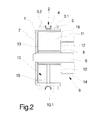
- FIG. 2 schematically shows sectional longitudinal view of the exemplary embodiment from FIG. 1 ;
- FIG. 3 schematically shows a cross-sectional view of the exemplary embodiment from FIG. 1 ;
- FIG. 4 schematically shows a cross-sectional view of a further exemplary embodiment of the cooling drum according to the invention.
- FIG. 5 schematically shows a fragment of a sectional longitudinal view of the exemplary embodiment from FIG. 4 ;
- FIG. 6 schematically shows a cross-sectional view of a further exemplary embodiment of the cooling drum according to the invention.
- FIG. 7 schematically shows a fragment of a sectional longitudinal view of the exemplary embodiment from FIG. 6 ;
- FIG. 8 schematically shows a side view of a further exemplary embodiment of the cooling drum according to the invention.
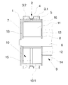
- FIGS. 1, 2 and 3 A first exemplary embodiment of the cooling drum according to the invention is illustrated in a plurality of views in FIGS. 1, 2 and 3 .
- FIG. 1 shows a side view
- FIG. 2 shows a sectional longitudinal view
- FIG. 3 shows a cross-sectional view of the exemplary embodiment.
- the exemplary embodiment of the cooling drum according to the invention has an annular cooling jacket 1 .
- a guide track 2 for receiving a thread plug is configured on the circumference of the cooling jacket 1 .
- the guide track 2 in this exemplary embodiment is formed by a perforated curved metal sheet 4 which is disposed between two spacers 3 . 1 and 3 . 2 .
- the spacers 3 . 1 and 3 . 2 are fixedly connected to the circumference of the cooling jacket 1 .
- the perforated metal sheet 4 having a multiplicity of smallest openings, is configured so as to be air-permeable.
- the cooling jacket 1 below the perforated metal sheet 4 has a plurality of jacket openings 5 which enclose the cooling jacket 1 as a perforation row.
- a suction chamber 11 is configured in the interior of the cooling jacket 1 .
- the suction chamber 11 is separated from the cooling jacket 1 and from an external end wall 7 by way of a shielding means 10 .
- the shielding means 10 in this exemplary embodiment is formed by an annular closed sealing jacket 10 . 1 which is held by way of an internal end wall 13 that is disposed laterally to the sealing jacket 10 . 1 .
- the closed internal end wall 13 is disposed in a protruding hollow support 8 and extends so as to be parallel with the external end wall 7 .
- the hollow support 8 therein is penetrated by the driveshaft 6 .
- An air slot 15 is configured on the sealing jacket 10 . 1 in the plane of the guide track 2 .
- the air slot 15 extends across a part-circumference of the sealing jacket 10 . 1 .
- the length of the air slot 15 is chosen so as to depend on the wrapping of the plug of the thread plug that is required for cooling and disintegrating the thread.
- the part-wrapping of the thread plug herein is ⁇ 360°.
- the internal suction chamber 11 is delimited by a dish-shaped collar 16 of the hollow support 8 .
- a suction connector 9 which in this exemplary embodiment is formed by a suction port 14 adjoins the collar 16 .
- the suction port 14 to this end is connected to the hollow support 8 .
- a plurality of suction openings 12 within the suction port 14 are configured on the collar 16 of the hollow support 8 .
- the suction openings 12 are opposite the internal end wall 13 .
- the cooling jacket 1 is rotatingly driven by way of the driveshaft 6 .
- a thread plug that has been produced in a texturing process is received on the circumference of the cooling jacket 1 within the guide track 2 and is guided on the cooling jacket 1 by way of a part-wrapping.
- the suction chamber 11 that is configured in the interior of the sealing jacket 10 . 1 by way of the suction openings 12 and by way of the suction port 14 is connected to a vacuum source. To this extent a vacuum is generated in the suction chamber 11 .
- the vacuum in the suction chamber 11 causes a suction flow on the air slot 15 , said suction flow acting on the guide track 2 .
- cooling air is suctioned from the environment by way of the guide track 2 and by way of the air slot 15 into the suction chamber 11 and is discharged by way of the suction port 14 .
- the ambient air herein penetrates the thread plug that bears on the circumference of the perforated metal sheet 4 and penetrates the cooling jacket 1 by way of the jacket openings 5 toward the air slot 15 .
- a targeted airflow is generated only in the region of the guide track 2 .
- sufficient cooling flows on the guide track 2 can already be generated by way of low vacuums.
- the relationship between the perforated metal sheet 4 and the jacket openings 5 and the air slot 15 herein can be optimized in terms of aerodynamics.
- the opening cross sections as well as the mutual spacings can thus be varied.
- the perforated metal sheet 4 typically has a larger opening cross section than the jacket openings 5
- the jacket openings 5 typically have a larger opening cross section than the air slot 15 .
- FIGS. 4 and 5 A further exemplary embodiment of a cooling drum according to the invention is illustrated in FIGS. 4 and 5 .
- a cross-sectional view is schematically shown in FIG. 4
- a fragment of a sectional longitudinal view is schematically shown in FIG. 5 .
- the exemplary embodiment as per FIGS. 4 and 5 is substantially identical to the exemplary embodiment as per FIGS. 1 to 3 such that only the points of differentiation are mentioned at this stage in order for repetitions to be avoided.
- two sealing strips 17 . 1 and 17 . 2 are assigned to the ends of the air slot 15 .
- the sealing strips 17 . 1 and 17 . 2 are disposed on the circumference of the sealing jacket 10 . 1 and in relation to the cooling jacket 1 form a sealing gap 18 .
- the sealing strips 17 . 1 and 17 . 2 are embodied so as to be elastic so as to be able to compensate for potential deviations in tolerances in the gap between the sealing jacket 10 and the cooling jacket 1 when the cooling jacket 1 rotates.
- the sealing strips 17 . 1 and 17 . 2 are axially aligned and enclose an annular suction zone 19 on the circumference of the sealing jacket 10 . 1 .
- the sealing strips 17 . 1 and 17 . 2 extend substantially across the entire width of the sealing jacket 10 . 1 . Since the sealing strips 17 . 1 and 17 . 2 are of identical configuration only the sealing strip 17 . 1 is illustrated in FIG. 5 .
- the cooling jacket 1 at the ends thereof has in each case one groove 22 . 1 and 22 . 2 in which in each case one sealing ring 20 . 1 and 20 . 2 is held.
- the sealing rings 20 . 1 and 20 . 2 at a free and protruding end have a lip seal 21 . 1 and 21 . 2 which is in frictional contact with the circumference of the sealing jacket 10 . 1 .
- a closed suction zone 19 results in the transition region between the sealing jacket 10 . 1 and the cooling jacket 1 below the guide track 2 .
- a highly targeted generation of cooling air without any substantial losses is thus possible.
- the exemplary embodiment illustrated in FIGS. 4 and 5 is particularly energy-saving and at relatively low vacuums enables intensive cooling of a thread plug that is guided on the circumference of the guide track 2 .
- Quasi a closed space in relation to the suction chamber 11 or to the environment, respectively, is formed on account of the radial seals 22 . 1 and 22 . 2 and of the sealing strips 17 . 1 and 17 . 2 .
- This space could thus have a positive pressure in relation to the environment so as to obtain a flow of blown air in the disintegration region on the circumference of the guide track 2 in order for the thread to be released in an improved manner.
- the space could also have a negative pressure in relation to the environment so as to cause a flow of suctioned air.
- the length of the air slot on the part-circumference of the sealing jacket 10 . 1 and the arrangement of the sealing strips 17 . 1 and 17 . 2 is chosen in such a manner that the entry of the thread plug in the angular range of the sealing strip 17 . 1 is repositioned, for example.
- the sealing strip 17 . 2 that follows in the running direction of the cooling jacket 1 represents that region in which a disintegration of the thread plug and a drawing-off of the thread on the circumference of the cooling jacket is performed.
- the disintegration and the drawing-off of the thread herein can be located in a non-suctioned zone of the cooling jacket 1 .
- FIGS. 6 and 7 a further exemplary embodiment of the cooling device according to the invention is illustrated in FIGS. 6 and 7 .
- FIG. 6 schematically shows a cross-sectional view
- FIG. 7 schematically shows a fragment of a sectional longitudinal view.
- the exemplary embodiment as per FIGS. 6 and 7 is substantially identical to the exemplary embodiment as per FIGS. 4 and 5 such that only the points of differentiation will be explained hereunder.
- a compressed-air duct 23 which is connected to the guide track 2 by way of a blower opening 24 is configured within the cooling jacket 1 .
- the compressed-air duct 23 by way of a compressed-air connector 25 that is configured on the collar 16 is connectable to a compressed-air source (not illustrated here).
- the compressed-air duct 23 is disposed on the sealing jacket 10 . 1 in an angular position in which a thread is released and drawn off from the thread plug.
- the release of the thread from the guide track 2 in operation is supported by way of a slight flow of blown air which by way of the blower opening 24 and by way of the jacket opening impacts the perforated metal sheet 4 .
- frictional contact of threads and catching of filaments on the porous perforated metal sheet 4 can be avoided.
- the cooling drum according to the invention is particularly suitable for cooling a plurality of thread plugs, as can be derived from the illustration of a further exemplary embodiment as per FIG. 8 .
- one image half is illustrated as a side view, and a second image half is illustrated as a sectional longitudinal view. Since the exemplary embodiment in terms of the basic construction is identical to the exemplary embodiments as per FIGS. 1 to 6 , the components with identical functions are provided with identical reference signs.
- a cooling jacket 1 is connected to a drive shaft 6 by way of an external end wall 7 .
- a plurality of encircling guide tracks 2 are configured so as to be parallel beside one another on the circumference of the cooling jacket 1 .
- the guide tracks 2 are formed by a plurality of spacers 3 . 1 to 3 . 4 and by a plurality of perforated metal sheet 4 .
- the perforated metal sheet 4 is embodied in a U-shape and has a multiplicity of finest perforations.
- a perforation row 5 of a plurality of jacket openings 5 is assigned to each of the perforated sheet-metal plates 4 in the cooling jacket 1 .
- An annular sealing jacket 10 . 1 which at the height of the guide tracks 2 has in each case one of a plurality of air slots 15 is provided within the cooling jacket 1 .
- One air slot 15 is thus assigned to each guide track 2 on the circumference of the cooling jacket 1 .
- the sealing jacket 10 . 1 by way of an internal end wall 13 is fixedly connected to a stationary hollow support 8 .
- the hollow support 8 on that collar side on the collar 16 that is opposite the internal end wall 13 has a plurality of suction openings 12 which by way of a suction port 14 are connected to a vacuum source (not illustrated here).
- a plurality of thread plugs can thus be simultaneously guided and cooled by way of a part-wrapping on the circumference of the cooling jacket.
- cooling drum according to the invention is also positively suitable for this purpose.
- FIGS. 1 to 8 in terms of the structure and the construction of the individual parts are exemplary. In principle, similar constructions can be chosen in order for a targeted suction flow to be generated by way of air slots of a sealing jacket.
- the exemplary embodiments by way of the features thereof can thus also be combined in an arbitrary manner so as to obtain new variants of embodiment.
- the invention is distinguished by a particularly gentle treatment of the threads.
- the installation size and the discharge ducts of the suction air can be reduced in size by virtue of lower vacuums.
Landscapes
- Engineering & Computer Science (AREA)
- Textile Engineering (AREA)
- Mechanical Engineering (AREA)
- Spinning Methods And Devices For Manufacturing Artificial Fibers (AREA)
- Continuous Casting (AREA)
- Thermotherapy And Cooling Therapy Devices (AREA)
Applications Claiming Priority (4)
| Application Number | Priority Date | Filing Date | Title |
|---|---|---|---|
| DE102015009040 | 2015-07-13 | ||
| DE102015009040.2 | 2015-07-13 | ||
| DE102015009040 | 2015-07-13 | ||
| PCT/EP2016/065907 WO2017009122A1 (de) | 2015-07-13 | 2016-07-06 | Kühltrommel zum abkühlen eines fadenstopfens |
Publications (2)
| Publication Number | Publication Date |
|---|---|
| US20180187346A1 US20180187346A1 (en) | 2018-07-05 |
| US10072363B2 true US10072363B2 (en) | 2018-09-11 |
Family
ID=56372893
Family Applications (1)
| Application Number | Title | Priority Date | Filing Date |
|---|---|---|---|
| US15/742,414 Expired - Fee Related US10072363B2 (en) | 2015-07-13 | 2016-07-06 | Cooling drum for cooling a thread plug |
Country Status (4)
| Country | Link |
|---|---|
| US (1) | US10072363B2 (de) |
| EP (1) | EP3322844B1 (de) |
| CN (1) | CN107849751A (de) |
| WO (1) | WO2017009122A1 (de) |
Cited By (1)
| Publication number | Priority date | Publication date | Assignee | Title |
|---|---|---|---|---|
| CN108468131A (zh) * | 2018-04-26 | 2018-08-31 | 湖州新爱品纺织有限公司 | 一种加弹机用水冷装置 |
Families Citing this family (2)
| Publication number | Priority date | Publication date | Assignee | Title |
|---|---|---|---|---|
| BE1024740B1 (nl) * | 2016-11-22 | 2018-06-18 | Wiele Michel Van De Nv | Inrichting en werkwijze voor het vervaardigen van gekroesd textielgaren en koeltrommel voor een dergelijke inrichting |
| CN112626629B (zh) * | 2020-12-15 | 2024-12-27 | 北京中丽制机工程技术有限公司 | 一种冷毂装置和纺丝装置 |
Citations (15)
| Publication number | Priority date | Publication date | Assignee | Title |
|---|---|---|---|---|
| US1838200A (en) * | 1927-12-06 | 1931-12-29 | Tomtlund Karl Helge | Pneumatic sheet laying-off device |
| US3217386A (en) * | 1965-11-16 | Yarn transfer drum | ||
| DE2146894A1 (de) | 1971-09-20 | 1973-03-29 | Vepa Ag | Verfahren und vorrichtung zum kontinuierlichen stauch-kraeuseln von faeden |
| US3816887A (en) * | 1972-07-17 | 1974-06-18 | Eastman Kodak Co | Swivelly mounted tailpipe for the jet device of a yarn bulking apparatus |
| UST925009I4 (en) * | 1974-02-12 | 1974-08-06 | Method and apparatus for forming three-dimensional crimf in yarn of continuous length filamentary thermoplastic material | |
| US4077466A (en) * | 1974-10-23 | 1978-03-07 | Vepa Ag | Heated roll, such as a godet, in drawing units, for example |
| US4118843A (en) * | 1976-07-16 | 1978-10-10 | Barmag Barmer Maschinenfabrik Aktiengesellschaft | Processes and apparatus for thermal treatment of filaments |
| US4301578A (en) * | 1978-03-03 | 1981-11-24 | Barmag Barmer Maschinenfabrik Ag | Process and apparatus for texturing thread |
| US4450607A (en) * | 1975-10-02 | 1984-05-29 | Allied Corporation | Method for texturizing continuous filaments |
| DE19613177A1 (de) | 1995-04-10 | 1996-10-17 | Barmag Barmer Maschf | Vorrichtung und Verfahren zum Strecken, Auflockern und Kühlen von Fadenstopfen |
| US5974777A (en) * | 1998-04-21 | 1999-11-02 | Davis; David M | Yarn texturizer cooling drum |
| US6128913A (en) * | 1998-06-22 | 2000-10-10 | Plantex S.P.A. Viale Europa | Device for the cooling of texturized yarns and texturizing apparatus fitted with said device |
| US6585139B1 (en) * | 1998-10-16 | 2003-07-01 | Achofen + Meier Ag Maschinenfabrik | Draw roller for strip material |
| US20040200048A1 (en) * | 2001-05-10 | 2004-10-14 | Diethard Hubner | Compressive crimping device for a synthetic multi-threaded yarn |
| US20090249765A1 (en) * | 2006-11-04 | 2009-10-08 | Oerlikon Textile Gmbh & Co. Kg | Method and apparatus for crimping a multifilament thread |
-
2016
- 2016-07-06 US US15/742,414 patent/US10072363B2/en not_active Expired - Fee Related
- 2016-07-06 WO PCT/EP2016/065907 patent/WO2017009122A1/de not_active Ceased
- 2016-07-06 EP EP16736429.8A patent/EP3322844B1/de not_active Not-in-force
- 2016-07-06 CN CN201680041254.5A patent/CN107849751A/zh active Pending
Patent Citations (15)
| Publication number | Priority date | Publication date | Assignee | Title |
|---|---|---|---|---|
| US3217386A (en) * | 1965-11-16 | Yarn transfer drum | ||
| US1838200A (en) * | 1927-12-06 | 1931-12-29 | Tomtlund Karl Helge | Pneumatic sheet laying-off device |
| DE2146894A1 (de) | 1971-09-20 | 1973-03-29 | Vepa Ag | Verfahren und vorrichtung zum kontinuierlichen stauch-kraeuseln von faeden |
| US3816887A (en) * | 1972-07-17 | 1974-06-18 | Eastman Kodak Co | Swivelly mounted tailpipe for the jet device of a yarn bulking apparatus |
| UST925009I4 (en) * | 1974-02-12 | 1974-08-06 | Method and apparatus for forming three-dimensional crimf in yarn of continuous length filamentary thermoplastic material | |
| US4077466A (en) * | 1974-10-23 | 1978-03-07 | Vepa Ag | Heated roll, such as a godet, in drawing units, for example |
| US4450607A (en) * | 1975-10-02 | 1984-05-29 | Allied Corporation | Method for texturizing continuous filaments |
| US4118843A (en) * | 1976-07-16 | 1978-10-10 | Barmag Barmer Maschinenfabrik Aktiengesellschaft | Processes and apparatus for thermal treatment of filaments |
| US4301578A (en) * | 1978-03-03 | 1981-11-24 | Barmag Barmer Maschinenfabrik Ag | Process and apparatus for texturing thread |
| DE19613177A1 (de) | 1995-04-10 | 1996-10-17 | Barmag Barmer Maschf | Vorrichtung und Verfahren zum Strecken, Auflockern und Kühlen von Fadenstopfen |
| US5974777A (en) * | 1998-04-21 | 1999-11-02 | Davis; David M | Yarn texturizer cooling drum |
| US6128913A (en) * | 1998-06-22 | 2000-10-10 | Plantex S.P.A. Viale Europa | Device for the cooling of texturized yarns and texturizing apparatus fitted with said device |
| US6585139B1 (en) * | 1998-10-16 | 2003-07-01 | Achofen + Meier Ag Maschinenfabrik | Draw roller for strip material |
| US20040200048A1 (en) * | 2001-05-10 | 2004-10-14 | Diethard Hubner | Compressive crimping device for a synthetic multi-threaded yarn |
| US20090249765A1 (en) * | 2006-11-04 | 2009-10-08 | Oerlikon Textile Gmbh & Co. Kg | Method and apparatus for crimping a multifilament thread |
Non-Patent Citations (2)
| Title |
|---|
| International Searching Authority, International Search Report (ISR) and Written Opinion for International Application No. PCT/EP2016/065907, dated Aug. 9, 2016, 12 pages, European Patent Office, Netherlands. |
| The International Bureau of WIPO, English translation of Written Opinion for International Application No. PCT/EP2016/065907, dated Jan. 25, 2018, 8 pages, Switzerland. |
Cited By (1)
| Publication number | Priority date | Publication date | Assignee | Title |
|---|---|---|---|---|
| CN108468131A (zh) * | 2018-04-26 | 2018-08-31 | 湖州新爱品纺织有限公司 | 一种加弹机用水冷装置 |
Also Published As
| Publication number | Publication date |
|---|---|
| EP3322844B1 (de) | 2019-05-01 |
| CN107849751A (zh) | 2018-03-27 |
| WO2017009122A1 (de) | 2017-01-19 |
| US20180187346A1 (en) | 2018-07-05 |
| EP3322844A1 (de) | 2018-05-23 |
Similar Documents
| Publication | Publication Date | Title |
|---|---|---|
| US20180187346A1 (en) | Cooling drum for cooling a thread plug | |
| US2397171A (en) | Fan and motor mounting | |
| US20160329778A1 (en) | Totally-enclosed traction motor | |
| EP2827024A1 (de) | Kühlluftstromführungsstruktur eines Fahrzeuggetriebes | |
| CN204042008U (zh) | 机械主轴的前端密封结构 | |
| RU99125762A (ru) | Охлаждаемая газом электромашина с осевым вентилятором | |
| RU2009141844A (ru) | Вентиляторное устройство для борьбы с вредными насекомыми | |
| CA2687706A1 (en) | Apparatus and method for heat recovery from rotary kilns | |
| JPS6110942A (ja) | 発電機のための通気装置 | |
| CN103611627A (zh) | 风冷式磁选滚筒及风冷式磁选装置 | |
| CA2815866C (en) | Suction roll for dewatering a fibrous web | |
| US20150218753A1 (en) | Sealing device and roller having a sealing device | |
| US20140252895A1 (en) | Radial blower air guide, system, and method of cooling | |
| BR102017020209A2 (pt) | Sistema de remoção de partículas de abrasão e de resfriamento combinados, instalação de máquina eletromecânica e método para fornecer resfriamento | |
| US11255335B2 (en) | Blower assembly for use in an air handling system and method for assembling the same | |
| CN111630756B (zh) | 电机 | |
| KR101233441B1 (ko) | 정압 보상형 지하주차장 환기장치를 이용한 환기방법 | |
| CN108796678A (zh) | 一种清梳联喂棉装置 | |
| CN103703177B (zh) | 用于产生编织结的装置 | |
| JPH0835134A (ja) | 紡績機械 | |
| US9003608B2 (en) | Working assembly with a cooling system, for a machine for opening fibers, in particular a carding machine | |
| US5117622A (en) | Fiber supply arrangement for open-end rotor spinning | |
| US2183079A (en) | Ventilating fan | |
| CN101589196B (zh) | 幅材成形机的干燥部中利用导辊导引织物和幅材的系统 | |
| TW202122689A (zh) | 吸塵裝置的抽風馬達 |
Legal Events
| Date | Code | Title | Description |
|---|---|---|---|
| AS | Assignment |
Owner name: OERLIKON TEXTILE GMBH & CO. KG, GERMANY Free format text: ASSIGNMENT OF ASSIGNORS INTEREST;ASSIGNOR:MATTHIES, CLAUS;REEL/FRAME:044548/0121 Effective date: 20171224 |
|
| FEPP | Fee payment procedure |
Free format text: ENTITY STATUS SET TO UNDISCOUNTED (ORIGINAL EVENT CODE: BIG.); ENTITY STATUS OF PATENT OWNER: LARGE ENTITY |
|
| STCF | Information on status: patent grant |
Free format text: PATENTED CASE |
|
| FEPP | Fee payment procedure |
Free format text: MAINTENANCE FEE REMINDER MAILED (ORIGINAL EVENT CODE: REM.); ENTITY STATUS OF PATENT OWNER: LARGE ENTITY |
|
| LAPS | Lapse for failure to pay maintenance fees |
Free format text: PATENT EXPIRED FOR FAILURE TO PAY MAINTENANCE FEES (ORIGINAL EVENT CODE: EXP.); ENTITY STATUS OF PATENT OWNER: LARGE ENTITY |
|
| STCH | Information on status: patent discontinuation |
Free format text: PATENT EXPIRED DUE TO NONPAYMENT OF MAINTENANCE FEES UNDER 37 CFR 1.362 |
|
| FP | Lapsed due to failure to pay maintenance fee |
Effective date: 20220911 |