US10034331B2 - Controlled electric induction heating of an electrically conductive workpiece in a solenoidal coil with flux compensators - Google Patents
Controlled electric induction heating of an electrically conductive workpiece in a solenoidal coil with flux compensators Download PDFInfo
- Publication number
- US10034331B2 US10034331B2 US12/344,423 US34442308A US10034331B2 US 10034331 B2 US10034331 B2 US 10034331B2 US 34442308 A US34442308 A US 34442308A US 10034331 B2 US10034331 B2 US 10034331B2
- Authority
- US
- United States
- Prior art keywords
- electrically conductive
- workpiece
- elongated workpiece
- conductive elongated
- flux
- Prior art date
- Legal status (The legal status is an assumption and is not a legal conclusion. Google has not performed a legal analysis and makes no representation as to the accuracy of the status listed.)
- Active, expires
Links
Images


Classifications
-
- H—ELECTRICITY
- H05—ELECTRIC TECHNIQUES NOT OTHERWISE PROVIDED FOR
- H05B—ELECTRIC HEATING; ELECTRIC LIGHT SOURCES NOT OTHERWISE PROVIDED FOR; CIRCUIT ARRANGEMENTS FOR ELECTRIC LIGHT SOURCES, IN GENERAL
- H05B6/00—Heating by electric, magnetic or electromagnetic fields
- H05B6/02—Induction heating
- H05B6/06—Control, e.g. of temperature, of power
- H05B6/08—Control, e.g. of temperature, of power using compensating or balancing arrangements
-
- H—ELECTRICITY
- H05—ELECTRIC TECHNIQUES NOT OTHERWISE PROVIDED FOR
- H05B—ELECTRIC HEATING; ELECTRIC LIGHT SOURCES NOT OTHERWISE PROVIDED FOR; CIRCUIT ARRANGEMENTS FOR ELECTRIC LIGHT SOURCES, IN GENERAL
- H05B6/00—Heating by electric, magnetic or electromagnetic fields
- H05B6/02—Induction heating
- H05B6/36—Coil arrangements
- H05B6/365—Coil arrangements using supplementary conductive or ferromagnetic pieces
-
- H—ELECTRICITY
- H05—ELECTRIC TECHNIQUES NOT OTHERWISE PROVIDED FOR
- H05B—ELECTRIC HEATING; ELECTRIC LIGHT SOURCES NOT OTHERWISE PROVIDED FOR; CIRCUIT ARRANGEMENTS FOR ELECTRIC LIGHT SOURCES, IN GENERAL
- H05B6/00—Heating by electric, magnetic or electromagnetic fields
- H05B6/02—Induction heating
- H05B6/10—Induction heating apparatus, other than furnaces, for specific applications
- H05B6/14—Tools, e.g. nozzles, rollers, calenders
-
- Y—GENERAL TAGGING OF NEW TECHNOLOGICAL DEVELOPMENTS; GENERAL TAGGING OF CROSS-SECTIONAL TECHNOLOGIES SPANNING OVER SEVERAL SECTIONS OF THE IPC; TECHNICAL SUBJECTS COVERED BY FORMER USPC CROSS-REFERENCE ART COLLECTIONS [XRACs] AND DIGESTS
- Y02—TECHNOLOGIES OR APPLICATIONS FOR MITIGATION OR ADAPTATION AGAINST CLIMATE CHANGE
- Y02P—CLIMATE CHANGE MITIGATION TECHNOLOGIES IN THE PRODUCTION OR PROCESSING OF GOODS
- Y02P10/00—Technologies related to metal processing
- Y02P10/25—Process efficiency
Definitions
- the present invention relates to electric induction heating of an electrically conductive workpiece positioned within a solenoidal induction coil.
- Electric induction heating can be used to heat electrically conductive materials. Induction heating may be used, for example, prior to forging, extrusion, rolling and other metal hot and warm forming operations. In other applications induction heating of electrically conductive workpieces can be used for heat treatment processes such as hardening, annealing, normalizing, stress relieving and tempering. Some applications require uniform heating of the entire workpiece, while other applications require heating of specific regions of the workpiece, or require heating to gradient temperatures through the workpiece such as an aluminum billet prior to an extrusion process.
- workpiece 90 which may be cylindrical in shape, is held in place within solenoidal induction coil 30 .
- Support structure for holding the workpiece within the coil is not shown in FIG. 1( a ) .
- the electrically conductive workpiece is inductively heated by magnetic coupling with the generally longitudinal flux field established by the flow of ac current through the coil.
- the workpiece is positioned in the coil so that the opposing ends of the coil overhang the opposing ends of the workpiece in the coil.
- the longitudinal central axis (designated X′ in FIG.
- the coil and workpiece may be coincident as shown in the figure, and the coil is generally shaped to coincide with the longitudinal surfaces of the workpiece, or to achieve varying degrees of induced heating along the length of the workpiece.
- the coil overhang distance, x oh at each end of the coil controls the shape of the flux field established in the interior overhang regions of the coil so that the flux field intensity established within the opposing ends of the workpiece provides for uniform heating along the length of the workpiece, including the opposing ends of the workpiece, as required in this example.
- a uniform longitudinal temperature T 1 (graphically illustrated in FIG.
- the overhang distance required to achieve this workpiece heating profile is affected by a number of parameters, including the outside diameter (OD) of the workpiece; the overall length of the workpiece; the workpiece's physical and metallurgical properties; coil geometry and the frequency of the ac power applied to the coil.
- workpiece characteristics is used to collectively describe the physical dimensions and metallurgical properties of the workpiece. Therefore different coils, each with unique characteristics, and possibly also different power supplies, are ideally used to uniformly heat workpieces of different sizes or different physical properties. However changing coils in an industrial environment to accommodate workpieces with different characteristics is time and cost ineffective. Therefore accommodations are often made to heat various sizes of workpieces in the same induction coil connected to one ac power source with varying degrees of success.
- Variation in the length of a workpiece heated in a single induction coil directly impacts the coil overhang distances at each end of the coil and, consequently, the temperature distribution along the overall length of the inductively heated workpiece.
- the end regions of the shorter workpiece that are exposed to greater coil overhang regions than the overhang regions for the longer workpieces will have excessive heat sources and, consequently, will be overheated relative to the central region of the shorter workpiece.
- FIG. 2( c ) each illustrate the same induction coil 30 used to inductively heat three workpieces having different dimensions.
- Workpiece 90 a in FIG. 2( a ) has an OD equal to OD 1 and an overall length equal to L 1 ;
- workpiece 90 b in FIG. 2( b ) has an OD equal to OD 1 and a length equal to L 2 , which is less than length L 1 ;
- workpiece 90 c in FIG. 2( c ) has an OD equal to OD 2 , which is less than outside diameter OD 1 and an overall length equal to L 1 .
- the coil overhang distance X oh1 provides the desired uniform temperature distribution along the overall length of the workpiece of the particular geometry shown in FIG. 2( a ) , but the same coil fails to provide temperature uniformity along the length of the workpieces of different geometries in FIG. 2( b ) and FIG. 2( c ) .
- two workpieces have the same shape but are fabricated from materials with different physical or metallurgical properties, for example metal alloys with different electrical resistivities ( ⁇ )
- using an induction coil and power supply designed to inductively heat the first of the two workpieces with an electrical resistivity of ⁇ 1 to a uniform longitudinal temperature distribution profile will result in overheating of the ends of the second workpiece that has an electrical resistivity ⁇ 2 , which is less than ⁇ 1 , due to the electromagnetic end effect.
- ⁇ 3 which is greater than ⁇ 1
- underheating of the ends of the second workpiece will result.
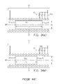
- FIG. 3( a ) and FIG. 3( b ) An alternative approach to a single solenoidal coil with power supply connections at opposing ends of the coil is a coil with multiple power supply tap connections 80 along the length at one end of the coil as diagrammatically illustrated in FIG. 3( a ) and FIG. 3( b ) .
- a power supply end tap 80 By selecting a power supply end tap 80 based upon the characteristics of the workpiece to be heated in the coil, the energized length of the coil, and therefore the overhang distances, can be changed to provide uniform heating of workpieces with different characteristics, such as workpiece 90 a ′ (utilizing end tap 80 b ) in FIG. 3( b ) , which is shorter in overall length than workpiece 90 a (utilizing end tap 80 a ) in FIG. 3( a ) .
- workpiece heating production time is lost when the taps are manually changed.
- One object of the present invention is to selectively control the induced heating temperature distribution profile of electrically conductive workpieces with different characteristics in the same induction coil or combination of induction coils.
- Another object of the present invention is to achieve a uniform temperature distribution profile along the overall length of electrically conductive workpieces with different characteristics in a single induction coil or combination of induction coils.
- Another object of the present invention is improving the versatility of an induction heating system comprising a single induction coil and power supply by selectively controlling the induced temperature profile of electrically conductive workpieces with different characteristics in the single induction coil.
- the present invention is an apparatus for, and method of electric induction heating of an electrically conductive workpiece in at least one solenoidal coil receiving power from an ac power source while at least one flux compensator is brought near to at least one end of the workpiece in the coil to affect the induced heating temperature profile for the workpiece.
- the flux compensator is selected based upon the characteristics of the workpiece to be inductively heated and the required induced heating temperature profile.
- the present invention is an apparatus for, and method of, controlling an induced longitudinally oriented, cross sectional heating profile in an electrically conductive workpiece without flux concentrators.
- the workpiece is positioned in a solenoidal type induction coil so that a coil overhang region exists adjacent to an end of the workpiece.
- a flux compensator is positioned in the coil overhang region with one end of the flux compensator proximate to the end of the workpiece to alter the induced longitudinally oriented, cross sectional heating profile in the end of the workpiece.
- an electromagnetic gap is provided between the opposing ends of the flux compensator and the workpiece.
- An alternating current is supplied to the induction coil to create the induced longitudinally oriented, cross sectional heating profile in the electrically conductive workpiece.
- FIG. 1( a ) illustrates in a cross sectional diagram, a solenoidal coil with an electrically conductive workpiece positioned in the coil so that the coil overhang distance is the same at both ends of the coil;
- FIG. 1( b ) graphically illustrates the uniform temperature profile that can be achieved along the length of the workpiece with the coil and workpiece arrangement shown in FIG. 1( a ) in idealized cross sectional isothermal region R iso shown in FIG. 1( c ) .
- FIG. 2( a ) ′, FIG. 2( b ) ′ and FIG. 2( c ) ′ illustrate the change in temperature distribution profiles along the overall length of workpieces with different characteristics when inductively heated in the same induction coil as illustrated in the arrangements shown in FIG. 2( a ) , FIG. 2( b ) and FIG. 2( c ) , respectively.
- FIG. 3( a ) and FIG. 3( b ) illustrate in cross sectional diagrams a multiple tap coil that can be used to compensate for induction heating of various workpieces with different characteristics to minimize the effects of irregular end heating of the various workpieces.
- FIG. 4( a ) , FIG. 4( b ) and FIG. 4( c ) illustrate in cross sectional diagrams one example of the electric induction heating apparatus of the present invention.
- FIG. 5( a ) illustrates in cross sectional diagram an electrically conductive workpiece inserted into an induction coil so that the coil overhang distances are the same at both end of the coil
- FIG. 5( b ) graphically illustrates a uniform temperature profile that can be achieved along the length of the workpiece with the coil and workpiece arrangement shown in FIG. 5( a ) .
- FIG. 6( a ) illustrates in cross section diagram another example of the electric induction heating apparatus of the present invention with FIG. 6( b ) graphically illustrating a uniform temperature profile that can be achieved along the length of the workpiece with the coil, workpiece and flux compensator arrangement shown in FIG. 6( a ) .
- FIG. 7( a ) illustrates in cross section diagram another example of the electric induction heating apparatus of the present invention with FIG. 7( b ) graphically illustrating a uniform temperature profile that can be achieved along the length of the workpiece with the coil, workpiece and flux compensator arrangement shown in FIG. 7( a ) .
- FIG. 8( a ) illustrates in cross section diagram another example of the electric induction heating apparatus of the present invention with FIG. 8( b ) graphically illustrating a non-uniform temperature profile that can be achieved along the length of the workpiece with the coil, workpiece and flux compensator arrangement shown in FIG. 8( a ) .
- FIG. 9( a ) illustrates in cross section diagram another example of the electric induction heating apparatus of the present invention with FIG. 9( b ) graphically illustrating a non-uniform temperature profile that can be achieved along the length of the workpiece with the coil, workpiece and flux compensator arrangement shown in FIG. 9( a ) .
- FIG. 10( a ) illustrates in cross sectional diagram another example of the electric induction heating apparatus of an electrically conductive workpiece of the present invention with FIG. 10( b ) graphically illustrating a non-uniform temperature profile that can be achieved along the length of the workpiece with the coil, workpiece and flux compensator arrangement shown in FIG. 10( a ) .
- FIG. 4( a ) One non-limiting example of the electric induction heating apparatus of the present invention for heating of an electrically conductive workpiece is diagrammatically illustrated in FIG. 4( a ) , FIG. 4( b ) and FIG. 4( c ) .
- the apparatus comprises a single multi-turn solenoidal induction coil 30 having an ac power supply (not shown in the figures) connected to the opposing ends of the coil to supply ac current to the coil, which generates a flux field around the coil that couples with the workpiece in the coil to inductively heat the coil.
- a flux compensator is selectively used during induction heating of workpieces with varying characteristics as further described below.
- the flux compensator may be a substantially solid or hollow disc.
- the compensator may be water cooled by providing suitable passages in the compensator and connecting the passages to a supply and return of a cooling medium such as water.
- Suitable workpiece conveying apparatus can be provided to insert a workpiece into the coil and remove it from inside the coil after heating.
- Suitable compensator conveying apparatus can be provided to insert the compensator into the coil and remove it from inside the coil after heating.
- Alternatively a combination of workpiece and compensator conveying apparatus may be provided.
- Workpiece 90 d in FIG. 4( a ) has an overall length of L 1 ; workpiece 90 e in FIG. 4( b ) has an overall length of L 3 , which is less than length L 1 ; and workpiece 90 f in FIG. 4( c ) has an overall length of L 4 , which is less than length L 3 .
- Workpiece 90 d in FIG. 4( a ) is of optimal length for induction heating with uniform temperature distribution along its overall length when the coil overhang distance X oh1 is the same at both ends of the coil as shown in FIG. 4( a ) .
- FIG. 4( a ) is of optimal length for induction heating with uniform temperature distribution along its overall length when the coil overhang distance X oh1 is the same at both ends of the coil as shown in FIG. 4( a ) .
- end surface 40 a ′ of compensator 40 a is brought in close proximity to end surface 90 e ′′ (designated “second end”) of workpiece 90 e to compensate for the shorter overall length of the workpiece so that overheating of the second end of the workpiece is mitigated.
- end surface 90 e is a non-magnetic stainless steel billet
- a distance of approximately 0.03-inch to approximately 1.8-inch between the opposing end surfaces of the workpiece and compensator may be considered a sufficiently small gap and therefore in close proximity.
- the flux compensator is formed from a material composition that has approximately the same, for example, approximately no greater than 10 to 15 percent variation in electromagnetic properties (primarily electrical resistivity and magnetic permeability) as the workpiece, and the difference in diameters of compensator 40 a and workpiece 90 e are approximately no greater than the one fourth of the depth of eddy current penetration into the workpiece, and the electromagnetic gap between compensator 40 a and workpiece 90 e is sufficiently small while utilizing medium frequency (that is, from about 1 kHz to about 10 kHz) of the power source, then there will be no appreciable disturbance of the electromagnetic field at the second end of workpiece 90 e as shown in FIG. 4( b ) and FIG. 6( a ) assuming a sufficiently long flux compensator.
- medium frequency that is, from about 1 kHz to about 10 kHz
- Induced heating temperature distribution (line T wp in FIG. 6( b ) ) along the overall length of workpiece 90 e in FIG. 6( a ) will be uniform, as it would be in the case of optimal coil overhang x oh1 as shown in FIG. 4( a ) and FIG. 5( a ) regardless of the fact that the actual coil overhang distance from the second end of the workpiece was increased from x oh1 (in FIG. 4( a ) and FIG. 5( a ) ) to x oh3 (in FIG. 4( b ) and FIG. 6( a ) ).
- Magnetic field disturbance at the coil's second end region is compensated for by use of flux compensator 40 a , and is localized within the compensator, which results in shifting temperature surplus T fc from the second end of the workpiece to compensator 40 a as graphically illustrated in FIG. 6( b ) .
- FIG. 4( c ) and FIG. 7( a ) illustrate an arrangement of the present invention wherein the overall length L 4 of workpiece 90 f is less than the overall length of workpiece 90 e shown in FIG. 4( b ) and FIG. 6( a ) , which results in a further increase of the coil overhang distance to x oh4 at the second end of workpiece 90 f , which is compensated for by use of flux compensator 40 b to achieve the uniform induced heating temperature distribution profile (line T wp ) shown in FIG. 7( b ) .
- the overall length of the utilized flux compensator depends upon the induced heating temperature distribution profile desired for the overall length of the workpiece.
- the utilized flux compensator should be of sufficient length to ensure that the end effect zone (where magnetic field disturbances take place) will be localized within the length of the adjacent flux compensator as shown represented by the non-uniform temperature distribution profile (curve T fc ) for compensator 40 b in FIG. 7( b ) .
- a non-uniform temperature distribution is required, for example a temperature gradient along the length of the second end of the workpiece, that end of the workpiece should be inductively heated to a temperature that is greater than the remainder of the overall length of the workpiece.
- the length of flux compensator will be shorter than that required for a uniform temperature distribution to assure that the end effect zone will not be localized within the flux compensator, but will occur in the end of the workpiece requiring the higher temperature.
- the flux compensator used in the induction heating apparatus and method of the present invention is not a flux concentrator, which is also known as a flux diverter, flux controller, magnetic shunt or magnetic core, and should not be made from materials typically used to fabricate flux concentrators.
- Physical properties of flux concentrators are significantly different from the properties of workpieces that the concentrators are used with in induction heating applications. Regardless of physical properties of the workpiece, the materials used as magnetic flux concentrators are soft magnetic in nature, which means that they become magnetic as soon as external magnetic field is applied.
- the types of materials most commonly used in induction heating for flux concentrators are laminations, electrolytic iron-based powder-type materials, carbonyl iron-based powder-type materials, pure ferrites and ferrite-based materials.
- Magnetic flux concentrators are fabricated in such a way that they would have very high electrical resistivity (ideally infinite electrical resistivity) and negligible eddy current losses.
- flux compensators are formed from materials that have similar electromagnetic properties to the workpiece that is being inductively heated. Therefore if the non-magnetic workpiece is formed from a relatively high electrically resistive material, for example, an austenitic stainless steel or titanium alloy composition, then the flux compensator should also be formed from a relatively high electrically resistive non-magnetic material. If the workpiece is formed from a material having a relatively low value of electrical resistivity, for example a gold, aluminum, silver, or copper alloy composition, then the flux compensator should also be formed from a low electrical resistivity material.
- the flux compensator used in the induction heating apparatus and method of the present invention is not a Faraday's induction ring, which is also known as a conductive shield, copper ring, copper cap or “robber” ring.
- Faraday's rings are passive shields basically representing single-turn shorted inductors that cancel, or dramatically reduce, the magnetic field of the source induction coil to improve shielding performances.
- the source induction coil induces eddy current within a Faraday's ring, which eddy current generates its own magnetic field that opposes and cancels the source field. Effectiveness of Faraday's rings and their shielding characteristics are noticeably decreased if high electrical resistivity materials are used for their fabrication. This is the reason why Faraday's rings are typically made from materials with low electrical resistivity such as, for example, a copper, aluminum or silver composition.
- FIG. 8( a ) and FIG. 9( a ) diagrammatically illustrate non-limiting exemplary arrangements of the present invention where the diameter of compensator 40 c is less than the diameter of workpiece 90 f , and where the diameter of compensator 40 d is greater than the diameter of workpiece 90 f , respectively.
- FIG. 8( b ) and FIG. 9( b ) graphically illustrate the corresponding non-uniform temperature distributions that result within workpiece 90 f .
- the diameter of the flux compensator is less than the diameter of the workpiece being inductively heated as shown in FIG. 8( a ) , then the end of the workpiece will have a surplus of heat sources and the second end workpiece temperature (curve T′ wp ) will be higher than temperature (line T wp ) throughout the other regions of the workpiece as graphically illustrated in FIG. 8( b ) . If the diameter of flux compensator is greater than the diameter of the workpiece being inductively heated as shown in FIG.
- FIG. 10( a ) diagrammatically illustrates one non-limiting exemplary arrangement of the present invention where the longitudinal temperature distribution (curve T′ wp ) near the second end of workpiece 90 f is non-uniform due to an electromagnetic gap L gap between compensator 40 e and workpiece 90 f .
- An electromagnetic gap is defined herein as a region occupied by a substantially non-electrically conductive and non-magnetic material.
- the flux compensator may have a thermal insulation plate (refractory) positioned in electromagnetic gap L gap .
- the thermal insulation plate may be physically attached to the facing end of compensator 40 e and make physical contact with the second end of the workpiece. If the thermal insulation plate is made from a non-electrically conductive and non-magnetic material, the plate will be effectively transparent to an electromagnetic field, and electromagnetically, behave as free space (acting as air or vacuum). Therefore even though there is no actual free space air gap between facing ends of the flux compensator and the workpiece, there is an electromagnetic gap resulting from the presence of the thermal insulating plate.
- Non-electrically conductive spacers, or spacers fabricated from electrically conductive materials that incorporate eddy current reduction features, such as radial and/or longitudinal slots, can also be used to establish an electromagnetic gap.
- the induction heating apparatus and method of the present invention utilizes one or more flux compensators with positioning, dimensions, composition and optional electromagnetic gap as disclosed herein to alter the induced heating temperature distribution profile of workpieces with different characteristics that are inserted into the same solenoidal coil for induction heating.
- a flux compensator may comprise two or more flux compensators joined together at facing ends.
- a flux compensator assembly can be provided wherein the assembly comprises a flux compensator (head element) mounted in a compensator holder that can be fastened to a compensator transfer apparatus to move the head element in and out of the coil.
- a series of interchangeable compensator head elements can be used in the assembly to accommodate induction heating of various workpieces with different characteristics in the same induction coil, and can be extended to using oval coils, channel inductors, and similar coils/inductors that can generically be described as solenoidal type coils.
- soldenoidal induction coil as used in the invention is understood in its broadest sense as any combination of one or more induction coils in which a magnetic field is generated when an ac current flows through the one or more induction coils, and the magnetic field couples with the electromagnetically conductive material inserted into the one or more induction coil.
- the invention is not limited to a particular geometric configuration of a solenoidal induction coil.
- the induction heating apparatus of the present invention can be used with electrically conductive workpieces of other shapes, for example either substantially solid or hollow cylindrically shaped workpieces, such as billets, bars, tubes and pipes; either solid or hollow rectangular and trapezoidal shaped workpieces, such as metal slabs, plates and blooms; or any other shape that can be inserted into an induction coil for induced heating as described above.
- Configuration and positioning of the utilized flux compensators can be altered to suit the particular shape of the workpiece being inductively heated. While diameter and (axial) length are parameters of interest for a cylindrical workpiece in use of the present invention, other parameters may be used for differently shaped workpieces.
- exemplar flux compensators in the above examples of the invention are generally in the shape of a disc, differently shaped compensators may be used to accommodate workpieces of various shapes in accordance with the apparatus and method of the present invention.
- the flux compensators used in the present invention can be cooled by a fluid medium and/or thermally insulated from the inductively heated workpiece, they may be used repetitively in the present invention while inductively heating successive workpieces without appreciable thermal fatigue.
- two separate flux compensators each one of which has an end facing each of the opposing ends of the workpiece in the induction coil may be used with the apparatus and method of the present induction.
Landscapes
- Physics & Mathematics (AREA)
- Electromagnetism (AREA)
- General Induction Heating (AREA)
Priority Applications (1)
| Application Number | Priority Date | Filing Date | Title |
|---|---|---|---|
| US12/344,423 US10034331B2 (en) | 2007-12-27 | 2008-12-26 | Controlled electric induction heating of an electrically conductive workpiece in a solenoidal coil with flux compensators |
Applications Claiming Priority (2)
| Application Number | Priority Date | Filing Date | Title |
|---|---|---|---|
| US1711107P | 2007-12-27 | 2007-12-27 | |
| US12/344,423 US10034331B2 (en) | 2007-12-27 | 2008-12-26 | Controlled electric induction heating of an electrically conductive workpiece in a solenoidal coil with flux compensators |
Publications (2)
| Publication Number | Publication Date |
|---|---|
| US20090166353A1 US20090166353A1 (en) | 2009-07-02 |
| US10034331B2 true US10034331B2 (en) | 2018-07-24 |
Family
ID=40796863
Family Applications (1)
| Application Number | Title | Priority Date | Filing Date |
|---|---|---|---|
| US12/344,423 Active 2032-07-25 US10034331B2 (en) | 2007-12-27 | 2008-12-26 | Controlled electric induction heating of an electrically conductive workpiece in a solenoidal coil with flux compensators |
Country Status (7)
| Country | Link |
|---|---|
| US (1) | US10034331B2 (de) |
| EP (1) | EP2236005B1 (de) |
| KR (1) | KR101532630B1 (de) |
| CN (1) | CN101919306A (de) |
| BR (1) | BRPI0821702B1 (de) |
| CA (1) | CA2708509C (de) |
| WO (1) | WO2009086488A2 (de) |
Cited By (1)
| Publication number | Priority date | Publication date | Assignee | Title |
|---|---|---|---|---|
| US20170094730A1 (en) * | 2015-09-25 | 2017-03-30 | John Justin MORTIMER | Large billet electric induction pre-heating for a hot working process |
Families Citing this family (14)
| Publication number | Priority date | Publication date | Assignee | Title |
|---|---|---|---|---|
| JP4563469B2 (ja) * | 2008-05-16 | 2010-10-13 | トヨタ自動車株式会社 | プレス加工方法及びプレス加工品 |
| AT512294B1 (de) * | 2012-04-10 | 2013-07-15 | Neuson Hydrotec Gmbh | Vorrichtung zum induktiven Erwärmen von Brammen |
| JP6194526B2 (ja) * | 2013-06-05 | 2017-09-13 | 高周波熱錬株式会社 | 板状ワークの加熱方法及び加熱装置並びにホットプレス成形方法 |
| WO2017002025A1 (en) * | 2015-06-30 | 2017-01-05 | Danieli & C. Officine Meccaniche S.P.A. | Transverse flux induction heating apparatus |
| JP2017050169A (ja) * | 2015-09-02 | 2017-03-09 | トヨタ自動車株式会社 | ロータコアの焼き嵌め方法 |
| JP6851749B2 (ja) * | 2016-08-24 | 2021-03-31 | キヤノン株式会社 | 被加熱部材の加熱方法および電子写真感光体の製造方法 |
| CN107326343B (zh) * | 2017-08-22 | 2020-05-12 | 中国科学院半导体研究所 | 用于薄膜材料生长的感应加热装置 |
| JP7199987B2 (ja) * | 2019-02-08 | 2023-01-06 | キヤノン株式会社 | 誘導加熱装置 |
| CN110315619B (zh) * | 2019-08-07 | 2021-03-23 | 中国林业科学研究院木材工业研究所 | 一种木制品弯曲构件成型方法及其装置 |
| CN111315059B (zh) * | 2020-03-12 | 2020-12-25 | 无锡利艾机械制造有限公司 | 电磁加热辊 |
| CN112981080B (zh) * | 2021-02-04 | 2021-11-23 | 燕山大学 | 一种铜管在线生产热处理装置及其工艺 |
| CN116099740B (zh) * | 2021-11-09 | 2023-07-28 | 北京科益虹源光电技术有限公司 | 一种带绕铁芯绝缘涂层制备方法 |
| DE102023113618A1 (de) * | 2023-05-24 | 2024-11-28 | Sms Group Gmbh | Induktionsheizvorrichtung, Betriebsverfahren, Produktionslinie, Verwendung einer derartigen Induktionsheizvorrichtung, Verwendung eines derartigen Betriebsverfahrens sowie Verwendung einer derartigen Produktionslinie |
| US12356530B1 (en) * | 2024-06-04 | 2025-07-08 | General Electric Company | Method of removing an insert from a substrate |
Citations (22)
| Publication number | Priority date | Publication date | Assignee | Title |
|---|---|---|---|---|
| US2299934A (en) * | 1940-12-16 | 1942-10-27 | Chrysler Corp | Inductive heating apparatus and method |
| GB2262420A (en) | 1991-12-03 | 1993-06-16 | Electricity Ass Tech | Induction heating apparatus |
| US5306365A (en) | 1992-11-19 | 1994-04-26 | Aluminum Company Of America | Apparatus and method for tapered heating of metal billet |
| US5448039A (en) | 1991-02-27 | 1995-09-05 | Fuji Electric Co., Ltd. | Billet induction heating device providing fast heating changeover for different size billets |
| US5550353A (en) | 1990-01-31 | 1996-08-27 | Inductotherm Corp. | Induction heating coil assembly for prevent of circulating current in induction heating lines for continuous-cast products |
| US5554836A (en) | 1994-05-23 | 1996-09-10 | The Boc Group, Inc. | Induction heating in low oxygen-containing atmosphere |
| US5821504A (en) | 1990-06-04 | 1998-10-13 | Nordson Corporation | Induction heating system for 360° curing of can body coatings |
| US5837976A (en) * | 1997-09-11 | 1998-11-17 | Inductotherm Corp. | Strip heating coil apparatus with series power supplies |
| US5844213A (en) | 1990-01-31 | 1998-12-01 | Inductotherm Corp. | Induction heating coil assembly for prevention of circulating currents in induction heating lines for continuous-cast products |
| US6091063A (en) * | 1998-11-06 | 2000-07-18 | The Boeing Company | Method for improving thermal uniformity in induction heating processes |
| US6437301B1 (en) | 1999-03-29 | 2002-08-20 | Tokuden Co., Ltd. | Induction heating roller apparatus |
| US6555801B1 (en) | 2002-01-23 | 2003-04-29 | Melrose, Inc. | Induction heating coil, device and method of use |
| US6576877B2 (en) | 2001-09-14 | 2003-06-10 | The Boeing Company | Induction processing with the aid of a conductive shield |
| US6635856B2 (en) | 2002-01-18 | 2003-10-21 | Inductotherm Corp. | Billet induction heating |
| US6730893B1 (en) | 1999-11-11 | 2004-05-04 | Sintef Energiforskning As | Induction heating apparatus |
| US6781100B2 (en) | 2001-06-26 | 2004-08-24 | Husky Injection Molding Systems, Ltd. | Method for inductive and resistive heating of an object |
| US6815649B2 (en) | 2001-07-25 | 2004-11-09 | I.A.S. Induktions-Anlagen + Service Gmbh & Co. Kg. | Device and method for inductive billet heating with a billet-heating coil |
| US7034263B2 (en) | 2003-07-02 | 2006-04-25 | Itherm Technologies, Lp | Apparatus and method for inductive heating |
| US7041944B2 (en) | 2001-06-26 | 2006-05-09 | Husky Injection Molding Systems, Ltd. | Apparatus for inductive and resistive heating of an object |
| US7214912B1 (en) | 2005-08-18 | 2007-05-08 | Christine P. Suszczynski | Installation method and material system for inductive billet heating coils |
| US20070235446A1 (en) * | 2006-03-29 | 2007-10-11 | Cao Mike Maochang | Transverse flux induction heating apparatus and compensators |
| US20070246459A1 (en) | 2006-04-24 | 2007-10-25 | Loveless Don L | Electric induction heat treatment of an end of tubular material |
-
2008
- 2008-12-26 EP EP08866281.2A patent/EP2236005B1/de not_active Not-in-force
- 2008-12-26 CA CA2708509A patent/CA2708509C/en active Active
- 2008-12-26 BR BRPI0821702-5A patent/BRPI0821702B1/pt not_active IP Right Cessation
- 2008-12-26 US US12/344,423 patent/US10034331B2/en active Active
- 2008-12-26 KR KR1020107013676A patent/KR101532630B1/ko not_active Expired - Fee Related
- 2008-12-26 CN CN2008801231082A patent/CN101919306A/zh active Pending
- 2008-12-26 WO PCT/US2008/088379 patent/WO2009086488A2/en not_active Ceased
Patent Citations (24)
| Publication number | Priority date | Publication date | Assignee | Title |
|---|---|---|---|---|
| US2299934A (en) * | 1940-12-16 | 1942-10-27 | Chrysler Corp | Inductive heating apparatus and method |
| US5550353A (en) | 1990-01-31 | 1996-08-27 | Inductotherm Corp. | Induction heating coil assembly for prevent of circulating current in induction heating lines for continuous-cast products |
| US5844213A (en) | 1990-01-31 | 1998-12-01 | Inductotherm Corp. | Induction heating coil assembly for prevention of circulating currents in induction heating lines for continuous-cast products |
| US5821504A (en) | 1990-06-04 | 1998-10-13 | Nordson Corporation | Induction heating system for 360° curing of can body coatings |
| US5448039A (en) | 1991-02-27 | 1995-09-05 | Fuji Electric Co., Ltd. | Billet induction heating device providing fast heating changeover for different size billets |
| US5510600A (en) * | 1991-12-03 | 1996-04-23 | Ea Technology Limited | Electromagnetic induction heating apparatus for heating elongated metal workpieces |
| GB2262420A (en) | 1991-12-03 | 1993-06-16 | Electricity Ass Tech | Induction heating apparatus |
| US5306365A (en) | 1992-11-19 | 1994-04-26 | Aluminum Company Of America | Apparatus and method for tapered heating of metal billet |
| US5554836A (en) | 1994-05-23 | 1996-09-10 | The Boc Group, Inc. | Induction heating in low oxygen-containing atmosphere |
| US5837976A (en) * | 1997-09-11 | 1998-11-17 | Inductotherm Corp. | Strip heating coil apparatus with series power supplies |
| US6091063A (en) * | 1998-11-06 | 2000-07-18 | The Boeing Company | Method for improving thermal uniformity in induction heating processes |
| US6437301B1 (en) | 1999-03-29 | 2002-08-20 | Tokuden Co., Ltd. | Induction heating roller apparatus |
| US6730893B1 (en) | 1999-11-11 | 2004-05-04 | Sintef Energiforskning As | Induction heating apparatus |
| US7041944B2 (en) | 2001-06-26 | 2006-05-09 | Husky Injection Molding Systems, Ltd. | Apparatus for inductive and resistive heating of an object |
| US6781100B2 (en) | 2001-06-26 | 2004-08-24 | Husky Injection Molding Systems, Ltd. | Method for inductive and resistive heating of an object |
| US6815649B2 (en) | 2001-07-25 | 2004-11-09 | I.A.S. Induktions-Anlagen + Service Gmbh & Co. Kg. | Device and method for inductive billet heating with a billet-heating coil |
| US6576877B2 (en) | 2001-09-14 | 2003-06-10 | The Boeing Company | Induction processing with the aid of a conductive shield |
| US6635856B2 (en) | 2002-01-18 | 2003-10-21 | Inductotherm Corp. | Billet induction heating |
| US6555801B1 (en) | 2002-01-23 | 2003-04-29 | Melrose, Inc. | Induction heating coil, device and method of use |
| US7034263B2 (en) | 2003-07-02 | 2006-04-25 | Itherm Technologies, Lp | Apparatus and method for inductive heating |
| US7214912B1 (en) | 2005-08-18 | 2007-05-08 | Christine P. Suszczynski | Installation method and material system for inductive billet heating coils |
| US20070235446A1 (en) * | 2006-03-29 | 2007-10-11 | Cao Mike Maochang | Transverse flux induction heating apparatus and compensators |
| US20080296290A1 (en) | 2006-03-29 | 2008-12-04 | Cao Mike Maochang | Transverse flux induction heating apparatus and compensators |
| US20070246459A1 (en) | 2006-04-24 | 2007-10-25 | Loveless Don L | Electric induction heat treatment of an end of tubular material |
Non-Patent Citations (15)
| Title |
|---|
| Advanced Induction Heating for Improved Stress Relief on API Pipes, GH Group-Spain, Tube and Pipe Technology, Nov./Dec. 2006, p. 76, USA (1 page total). |
| Advanced Induction Heating for Improved Stress Relief on API Pipes, GH Group—Spain, Tube and Pipe Technology, Nov./Dec. 2006, p. 76, USA (1 page total). |
| Chester A. Tudbury, Basics of Induction Heating, May 1960, pp. 1-50, 1-51 and 1-52, vol. 1, Rider, New York (5 pages total). |
| E.J. Davies, Conduction and Induction Heating, 1990, pp. 246, 247 and 281, Peter Peregrinus Ltd., London UK (4 pages total). |
| G.W.C. Kaye & T.H. Laby, Table of Physical and Chemical Constants, 14th ed, Longman (Wikipedia); 1973. * |
| Journal of Magnetism and Magnetic Materials 214-Microstructure, frequency and temperature-dependent dielectric properties of cobalt-substituted lithium ferrites (Wikipedia); Feb. 2, 2000. * |
| Journal of Magnetism and Magnetic Materials 214—Microstructure, frequency and temperature-dependent dielectric properties of cobalt-substituted lithium ferrites (Wikipedia); Feb. 2, 2000. * |
| M.G. Lozinskii, Industrial Applications of Induction Heating, 1969, pp. 598-599, Pergamon Press Ltd., London (3 pages total). |
| Maurice Orfueil, Electric Process Heating, 1987, pp. 416-417, 420-423, Battelle Press, Columbus, Ohio USA (5 pages total). |
| S. Zinn and S.L. Semiatin, Elements of Induction Heating: Design, Control and Applications, 1988, pp. 193, 194, 198-200, 241-246, ASM International, Metals Park, OH (13 pages total). |
| S.L. Semiatin and D.E Stutz, Induction Heat Treatment of Steel, 1986, pp. 75-77, American Society for Metals, Metals, Park, OH (5 pages total). |
| V. Rudnev and R. Cook, Magnetic Flux Concentrators: Myths, Realities and Profits, Metal Heat Treating, Mar./Apr. 1995, pp. 31-34, Penton Publishing Inc., USA (4 pages total). |
| V. Rudnev, An Objective Assessment of Magnetic Flux Concentrators, Heat Treating Process, ASM International, Nov. 2004, pp. 19-23, Ohio (5 pages total). |
| V. Rudnev, and R. Cook, Understanding Induction Bar End Heating, Reprinted from Forging, Winter 1995, (4 pages), Penton Publishing Inc., USA (4 pages total). |
| Valery Rudnev, Don Loveless, Raymond Cook and Micah Black, Handbook of Induction Heating, 2003, pp. 499-509, Marcel Dekker, Inc., New York NY (13 pages total). |
Cited By (1)
| Publication number | Priority date | Publication date | Assignee | Title |
|---|---|---|---|---|
| US20170094730A1 (en) * | 2015-09-25 | 2017-03-30 | John Justin MORTIMER | Large billet electric induction pre-heating for a hot working process |
Also Published As
| Publication number | Publication date |
|---|---|
| CA2708509A1 (en) | 2009-07-09 |
| CA2708509C (en) | 2017-11-14 |
| BRPI0821702A2 (pt) | 2015-06-16 |
| WO2009086488A3 (en) | 2009-09-17 |
| EP2236005B1 (de) | 2017-03-01 |
| KR101532630B1 (ko) | 2015-06-30 |
| KR20100098410A (ko) | 2010-09-06 |
| EP2236005A4 (de) | 2013-07-31 |
| BRPI0821702B1 (pt) | 2019-02-19 |
| EP2236005A2 (de) | 2010-10-06 |
| US20090166353A1 (en) | 2009-07-02 |
| CN101919306A (zh) | 2010-12-15 |
| WO2009086488A2 (en) | 2009-07-09 |
Similar Documents
| Publication | Publication Date | Title |
|---|---|---|
| US10034331B2 (en) | Controlled electric induction heating of an electrically conductive workpiece in a solenoidal coil with flux compensators | |
| US4447690A (en) | Inductive preheating of upset tubing | |
| US6555801B1 (en) | Induction heating coil, device and method of use | |
| US4122321A (en) | Induction heating furnace | |
| EP2900036B1 (de) | Hochfrequente induktionserwärmungsvorrichtung und verarbeitungsvorrichtung | |
| US11846001B2 (en) | Split multiple coil electric induction heat treatment systems for simultaneous heating of multiple features of a bearing component | |
| US20060255029A1 (en) | Flux guide induction heating device and method of inductively heating elongated and nonuniform workpieces | |
| Goldstein | Magnetic flux controllers in induction heating and melting | |
| KR101822508B1 (ko) | 복합 워크피스의 싱글 샷 유도 가열을 위한 인덕터 | |
| WO2014088423A1 (en) | Apparatus and method for induction heating of magnetic materials | |
| Rudnev | Induction heating of selective regions | |
| RU2103843C1 (ru) | Индукционная нагревательная установка | |
| Calta | Optimal induction heating process prior to forming | |
| CN102220475A (zh) | 细钢丝二级加热热处理的方法及设备 | |
| JP5153484B2 (ja) | 加熱部位選択的誘導加熱方法 | |
| JP2021025079A (ja) | 電磁誘導加熱装置 | |
| JP4890278B2 (ja) | 金属板の誘導加熱装置 | |
| JP5438817B2 (ja) | 加熱部位選択的誘導加熱装置 | |
| HK1216549B (en) | Inductor for single-shot induction heating of complex workpieces | |
| Lupi et al. | Estimation of the Basic Induction Process Parameters |
Legal Events
| Date | Code | Title | Description |
|---|---|---|---|
| AS | Assignment |
Owner name: INDUCTOHEAT, INC., MICHIGAN Free format text: ASSIGNMENT OF ASSIGNORS INTEREST;ASSIGNORS:RUDNEV, VALERY I.;LOVELESS, DON L.;REEL/FRAME:022548/0925 Effective date: 20090318 |
|
| STCF | Information on status: patent grant |
Free format text: PATENTED CASE |
|
| MAFP | Maintenance fee payment |
Free format text: PAYMENT OF MAINTENANCE FEE, 4TH YEAR, LARGE ENTITY (ORIGINAL EVENT CODE: M1551); ENTITY STATUS OF PATENT OWNER: LARGE ENTITY Year of fee payment: 4 |
|
| MAFP | Maintenance fee payment |
Free format text: PAYMENT OF MAINTENANCE FEE, 8TH YEAR, LARGE ENTITY (ORIGINAL EVENT CODE: M1552); ENTITY STATUS OF PATENT OWNER: LARGE ENTITY Year of fee payment: 8 |