US10031298B2 - Extended access optical fiber connector ferrule - Google Patents
Extended access optical fiber connector ferrule Download PDFInfo
- Publication number
- US10031298B2 US10031298B2 US15/286,792 US201615286792A US10031298B2 US 10031298 B2 US10031298 B2 US 10031298B2 US 201615286792 A US201615286792 A US 201615286792A US 10031298 B2 US10031298 B2 US 10031298B2
- Authority
- US
- United States
- Prior art keywords
- ferrule
- access opening
- fiber optic
- extended access
- optical fibers
- Prior art date
- Legal status (The legal status is an assumption and is not a legal conclusion. Google has not performed a legal analysis and makes no representation as to the accuracy of the status listed.)
- Active
Links
Images


Classifications
-
- G—PHYSICS
- G02—OPTICS
- G02B—OPTICAL ELEMENTS, SYSTEMS OR APPARATUS
- G02B6/00—Light guides; Structural details of arrangements comprising light guides and other optical elements, e.g. couplings
- G02B6/24—Coupling light guides
- G02B6/36—Mechanical coupling means
- G02B6/38—Mechanical coupling means having fibre to fibre mating means
- G02B6/3807—Dismountable connectors, i.e. comprising plugs
- G02B6/3873—Connectors using guide surfaces for aligning ferrule ends, e.g. tubes, sleeves, V-grooves, rods, pins, balls
- G02B6/3885—Multicore or multichannel optical connectors, i.e. one single ferrule containing more than one fibre, e.g. ribbon type
-
- G—PHYSICS
- G02—OPTICS
- G02B—OPTICAL ELEMENTS, SYSTEMS OR APPARATUS
- G02B6/00—Light guides; Structural details of arrangements comprising light guides and other optical elements, e.g. couplings
- G02B6/24—Coupling light guides
- G02B6/36—Mechanical coupling means
- G02B6/38—Mechanical coupling means having fibre to fibre mating means
- G02B6/3807—Dismountable connectors, i.e. comprising plugs
- G02B6/3833—Details of mounting fibres in ferrules; Assembly methods; Manufacture
- G02B6/3855—Details of mounting fibres in ferrules; Assembly methods; Manufacture characterised by the method of anchoring or fixing the fibre within the ferrule
- G02B6/3861—Adhesive bonding
-
- G—PHYSICS
- G02—OPTICS
- G02B—OPTICAL ELEMENTS, SYSTEMS OR APPARATUS
- G02B6/00—Light guides; Structural details of arrangements comprising light guides and other optical elements, e.g. couplings
- G02B6/24—Coupling light guides
- G02B6/36—Mechanical coupling means
- G02B6/38—Mechanical coupling means having fibre to fibre mating means
- G02B6/3807—Dismountable connectors, i.e. comprising plugs
- G02B6/3873—Connectors using guide surfaces for aligning ferrule ends, e.g. tubes, sleeves, V-grooves, rods, pins, balls
- G02B6/3882—Connectors using guide surfaces for aligning ferrule ends, e.g. tubes, sleeves, V-grooves, rods, pins, balls using rods, pins or balls to align a pair of ferrule ends
-
- G—PHYSICS
- G02—OPTICS
- G02B—OPTICAL ELEMENTS, SYSTEMS OR APPARATUS
- G02B6/00—Light guides; Structural details of arrangements comprising light guides and other optical elements, e.g. couplings
- G02B6/24—Coupling light guides
- G02B6/36—Mechanical coupling means
- G02B6/38—Mechanical coupling means having fibre to fibre mating means
- G02B6/3807—Dismountable connectors, i.e. comprising plugs
- G02B6/3887—Anchoring optical cables to connector housings, e.g. strain relief features
-
- G—PHYSICS
- G02—OPTICS
- G02B—OPTICAL ELEMENTS, SYSTEMS OR APPARATUS
- G02B6/00—Light guides; Structural details of arrangements comprising light guides and other optical elements, e.g. couplings
- G02B6/24—Coupling light guides
- G02B6/36—Mechanical coupling means
- G02B6/38—Mechanical coupling means having fibre to fibre mating means
- G02B6/3807—Dismountable connectors, i.e. comprising plugs
- G02B6/389—Dismountable connectors, i.e. comprising plugs characterised by the method of fastening connecting plugs and sockets, e.g. screw- or nut-lock, snap-in, bayonet type
- G02B6/3893—Push-pull type, e.g. snap-in, push-on
-
- G—PHYSICS
- G02—OPTICS
- G02B—OPTICAL ELEMENTS, SYSTEMS OR APPARATUS
- G02B6/00—Light guides; Structural details of arrangements comprising light guides and other optical elements, e.g. couplings
- G02B6/24—Coupling light guides
- G02B6/36—Mechanical coupling means
- G02B6/40—Mechanical coupling means having fibre bundle mating means
- G02B6/403—Mechanical coupling means having fibre bundle mating means of the ferrule type, connecting a pair of ferrules
Definitions
- Fiber optics have become the standard cabling medium used to meet the growing needs of data volume and transmission speeds of modern communication networks. Although fiber optic cabling is capable of providing the necessary high bandwidth data communication, proper installation of fiber optic components requires substantial costs and resources. Termination of the optical fibers is an important step in the installation process. However, using conventional technology, installation remains a time consuming, meticulous process that is prone to error. Individual optical fibers are typically extremely small. For example, even with protective coatings, optical fibers may only be about 250 microns in diameter. Nonetheless, the ends of the optical fibers must line up and form a continuous fiber optic connection. In addition, manipulation of a connector during installation and/or maintenance may stress the optical fibers, and possibly result in breakage of a fiber or fibers. Accordingly, fiber optic systems would benefit from technology capable of reducing inefficiencies and errors in fiber optic cable installations.
- a fiber optic ferrule comprising a ferrule body having a plurality of optical fiber insertion holes at a first end thereof, the plurality of optical fiber insertion holes being configured to receive a plurality of optical fibers, and an extended access opening arranged at a top surface of a second end of the ferrule body located opposite the first end, the extended access opening being configured to provide open access to substantially an entirety of an interior space within the ferrule body.
- the fiber optic ferrule may be an MT ferrule.
- the extended access opening may be configured to allow the plurality of optical fibers to be placed down into the interior space of the ferrule body.
- a flange may be located around a portion of the second end, the flange comprising two projections, each of the two projections protruding into the extended access opening to engage a fiber optic cable boot inserted into the interior space of the ferrule body.
- a fiber optic ferrule comprising a ferrule body defining an interior space therein and having a plurality of optical fiber insertion holes configured to receive a plurality of optical fibers, and an extended access opening arranged at least at a top surface of the ferrule body, the extended access opening being configured to provide open access to a substantial portion of the interior space.
- said extended access opening may be configured to facilitate the alignment of the plurality of optical fibers into the plurality of optical fiber insertion holes. In some embodiments, said extended access opening may be further configured to receive an adhesive. In some embodiments, the extended access opening may be further configured to receive the plurality of optical fibers to the interior space through the top surface of the ferrule body.
- FIGS. 1A and 1B depict a fiber optic ferrule
- FIGS. 2A and 2B depict an extended access ferrule according to some embodiments.
- the described technology generally relates to data transmission elements, including fiber optic connectors and connector components.
- the fiber optic connector components may include a fiber optic ferrule configured to connect with a corresponding fiber optic adapter.
- a fiber optic ferrule may be configured to provide increased access to the internal components thereof to, for instance, increase the efficiency of, reduce the time required to, and/or otherwise facilitate the termination of fiber optic connectors.
- the data transmission elements may include ferrules configured for various connection components, including, without limitation, mechanical transfer (MT), multiple-fiber push-on/pull-off (MPO), and multi-fiber MTP® connectors (“MTP”).
- MT mechanical transfer
- MPO multiple-fiber push-on/pull-off
- MTP® connectors multi-fiber MTP® connectors
- ferrules configured according to some embodiments may be formed to operate in accordance with JIS C 5981, IEC 61754-5, IEC-61754-7, “Fibre optic interconnecting devices and passive components—Fibre optic connector interfaces—Part 7: Type MPO connector family,” and TIA-604-5-D “Fiber Optic Connector Intermateability Standard, Type MPO.”
- a male MT ferrule may generally include at least two guide pins for high-accuracy positioning of each optical fiber in the ferrule.
- a female MT ferrule body may include two guide pin holes on an end surface of the ferrule for receiving the guide pins therein, and may have a plurality of optical fiber holes for receiving optical fibers. The optical fibers may be inserted into the optical fiber insertion holes from a rear end of the MT ferrule, for example, a female MT ferrule, and may be fixed in place with adhesive, such as an epoxy.
- An adapter may be used for face-to face joining of two MT ferrules. For instance, two MT ferrules, one with guide pins installed (male connector) and one without guide pins (female connector) may be inserted into opposite ends of an adapter such that the two ferrules may be aligned as the male guide pins enter the female guide pin holes.
- a non-limiting example of a connector that uses MT ferrules is an MPO connector.
- the MT ferrules may be pushed together within an adapter to optically connect the ferrules (forming a “physical contact” (PC) connection), wherein the optical fibers in one ferrule contact the optical fibers in the other ferrule and get compressed together to provide an optical connection.
- Optical transmission performance between the optical fibers is strongly dependent on connecting conditions such as axis alignment and inclination of the optical fibers, and gaps between the opposing optical fibers.
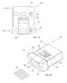
- FIGS. 1A and 1B depict a fiber optic ferrule.
- a ferrule 105 may include a ferrule body 160 having a first end 110 and a second end 115 .
- the first end 110 may be configured to be inserted into corresponding adapter (not shown), such as an MPO adapter.
- the second end 115 may be configured to engage a fiber optic connector housing (not shown).
- the second end 115 may include an opening 155 configured for receiving an end of a multi-fiber optical cable 145 .
- the multi-fiber optical cable 145 may be a ribbon cable of a plurality of individual optical fibers.
- the first end 110 may include a connection end face having a plurality of optical fiber insertion holes 135 arranged in one or more rows. Individual optical fibers of the multi-fiber cable 145 may be arranged in the holes 135 to terminate at the connection end face.
- the second end 115 may include a flange 120 having guide pin holes 150 (or guide pins on a male ferrule) arranged therein.
- the optical fibers of the multi-fiber optical cable 145 may be inserted through the cable opening 155 and into the optical fiber insertion holes 135 .
- a top surface 125 of the ferrule 105 may include an access opening 130 that allows an installer to see the optical fibers of the multi-fiber optical cable 145 as they are being inserted into the ferrule and into the optical fiber insertion holes 135 .
- the access opening 130 may provide some assistance to the installer for guiding the optical fibers into the insertion holes 135 .
- the optical fibers may be fixed in place by use of an adhesive that may be injected into the interior of the ferrule 105 , for example, through the access opening 130 and/or the cable opening 155 .
- the ferrule 105 includes an access opening 130 for visualizing the internal volume of the ferrule, in some circumstances it may still be challenging for an installer to accurately and efficiently insert the optical fibers and make a secure connection with the optical fiber insertion holes 135 .
- the access opening 130 may be of a generally small size and may provide only a very restricted view and access to the interior of the ferrule 105 .
- adequate access to the interior of the ferrule 105 may be prevented because an installer may not be able to access the interior of the ferrule bounded by area 140 due to the material of the flange 120 and the top surface 125 that blocks such access.
- the benefit of the access opening 130 may be limited and, in particular, it may be difficult for an installer to be able to adequately locate the insertion holes 135 during the critical step of insertion of the optical fibers.
- FIGS. 2A and 2B depict an extended access ferrule according to some embodiments.
- FIG. 2A depicts a top view of an extended access ferrule 205 having a first end 210 and a second end 215 having an opening 255 and a flange 220 disposed around a portion of the opening.
- the extended access ferrule 205 may include an extended access opening 230 arranged on a top surface 225 that provides access to an interior of the ferrule within area 260 , which was not accessible in ferrule 105 (e.g., depicted as area 140 in FIGS. 1A and 1B ).
- an installer has an increased area of accessibility to the interior of the extended access ferrule 205 to connect the multi-fiber optical cable 245 into the insertion holes 235 .
- the extended access opening 230 of the extended access ferrule 205 does not include a lid or cover and facilitates the alignment of the optical fibers of the multi-fiber optical cable 145 into the insertion holes 235 .
- a portion of the multi-fiber optical cable 245 may be arranged within a boot 265 (or other type of housing).
- the flange 220 may include projections 270 configured to engage a top portion 275 of the boot 265 to restrict or prevent movement of the housing away from and/or out of the interior of the extended access ferrule 205 .
- the multi-fiber optical cable 145 Using a conventional ferrule, an installer is required to insert the multi-fiber optical cable 145 through the opening 155 in a direction from the first end 110 to the second end 115 .
- the multi-fiber optical cable 145 must be placed on grooves (e.g., v-grooves) in the interior of the ferrule 105 and pushed at the correct angle to move the multi-fiber optical cable 145 into contact with the insertion holes 135 . This process is inefficient and error prone.
- an installer using an extended access ferrule 205 may place the multi-fiber optical cable 145 into the interior of the extended access ferrule through a top of the extended access via the extended access opening 230 ferrule (i.e., the access opening as extended through area 260 ) because the installer has access to area, thereby facilitating more efficient and accurate optical fiber installation in the insertion holes 235 .
- an installer may place pre-cleaved optical fibers down onto the grooves (e.g., v-grooves) within the extended access ferrule 205 and then the installer may slide the boot 265 into place within the extended access ferrule 205 .
- the optical fibers may be fixed in place on portions of and/or within the extended access ferrule 205 through the use of an adhesive.
- an installer using an extended access ferrule 205 may terminate optical fiber connections (such as MPO connections using an extended access MT ferrule) faster and more accurately than the installer would be capable of terminating using conventional ferrules. This leads to decreased costs and reduced time requirements for terminating fiber optic connections in a network using extended access ferrules 205 .
- compositions, methods, and devices are described in terms of “comprising” various components or steps (interpreted as meaning “including, but not limited to”), the compositions, methods, and devices can also “consist essentially of” or “consist of” the various components and steps, and such terminology should be interpreted as defining essentially closed-member groups.
- a range includes each individual member.
- a group having 1-3 cells refers to groups having 1, 2, or 3 cells.
- a group having 1-5 cells refers to groups having 1, 2, 3, 4, or 5 cells, and so forth.
Landscapes
- Physics & Mathematics (AREA)
- General Physics & Mathematics (AREA)
- Optics & Photonics (AREA)
- Mechanical Coupling Of Light Guides (AREA)
Priority Applications (1)
| Application Number | Priority Date | Filing Date | Title |
|---|---|---|---|
| US15/286,792 US10031298B2 (en) | 2015-10-06 | 2016-10-06 | Extended access optical fiber connector ferrule |
Applications Claiming Priority (2)
| Application Number | Priority Date | Filing Date | Title |
|---|---|---|---|
| US201562237675P | 2015-10-06 | 2015-10-06 | |
| US15/286,792 US10031298B2 (en) | 2015-10-06 | 2016-10-06 | Extended access optical fiber connector ferrule |
Publications (2)
| Publication Number | Publication Date |
|---|---|
| US20170097473A1 US20170097473A1 (en) | 2017-04-06 |
| US10031298B2 true US10031298B2 (en) | 2018-07-24 |
Family
ID=58446708
Family Applications (1)
| Application Number | Title | Priority Date | Filing Date |
|---|---|---|---|
| US15/286,792 Active US10031298B2 (en) | 2015-10-06 | 2016-10-06 | Extended access optical fiber connector ferrule |
Country Status (4)
| Country | Link |
|---|---|
| US (1) | US10031298B2 (zh) |
| CN (1) | CN108027478B (zh) |
| TW (1) | TW201719213A (zh) |
| WO (1) | WO2017062546A1 (zh) |
Families Citing this family (4)
| Publication number | Priority date | Publication date | Assignee | Title |
|---|---|---|---|---|
| WO2018074024A1 (ja) * | 2016-10-19 | 2018-04-26 | 住友電気工業株式会社 | 光コネクタフェルール及び光コネクタ |
| WO2020010585A1 (zh) * | 2018-07-12 | 2020-01-16 | 华为技术有限公司 | 光耦合装置及其封装方法、光模块及通讯设备 |
| CN109307913B (zh) * | 2018-12-10 | 2024-02-13 | 浙江申华电子科技有限公司 | 一种取光插芯以及光纤适配器 |
| CN115291337A (zh) * | 2022-07-25 | 2022-11-04 | 无锡芯光互连技术研究院有限公司 | 一种mt接口光纤连接和固定装置 |
Citations (7)
| Publication number | Priority date | Publication date | Assignee | Title |
|---|---|---|---|---|
| US20020146215A1 (en) | 2001-03-16 | 2002-10-10 | Takahiro Ogawa | Double-sided ferrule manufacturing method, auxiliary member used therein, end surface polishing method for double-sided ferrule, optical connector assembling method, optical connector, guide pin, and optical connector connecting method using the same |
| US6761489B1 (en) * | 1999-12-14 | 2004-07-13 | Corning Cable Systems Llc | Ferrule having first and second body portions with different nominal widths and an associated mold and fabrication method |
| US20050036742A1 (en) * | 2003-08-29 | 2005-02-17 | Dean David L. | Molded fiber optic ferrule with integrally formed geometry features |
| US20060115217A1 (en) * | 2004-11-29 | 2006-06-01 | Us Conec, Ltd. | Multi-fiber ferrule and a mold therefor |
| US20060204178A1 (en) | 2005-03-10 | 2006-09-14 | Thomas Theuerkorn | Multi-fiber fiber optic receptacle and plug assembly |
| US20090257718A1 (en) | 2008-02-25 | 2009-10-15 | Fujikura Ltd. | Optical connector having optical fiber |
| US8529138B2 (en) * | 2010-07-15 | 2013-09-10 | Tyco Electronics Corporation | Ferrule for optical transports |
Family Cites Families (2)
| Publication number | Priority date | Publication date | Assignee | Title |
|---|---|---|---|---|
| JP3470320B1 (ja) * | 2002-10-24 | 2003-11-25 | 日本航空電子工業株式会社 | 光コネクタ装置 |
| CN104330852B (zh) * | 2013-07-22 | 2017-10-31 | 深圳日海通讯技术股份有限公司 | 光纤连接器 |
-
2016
- 2016-10-05 TW TW105132191A patent/TW201719213A/zh unknown
- 2016-10-06 WO PCT/US2016/055641 patent/WO2017062546A1/en active Application Filing
- 2016-10-06 US US15/286,792 patent/US10031298B2/en active Active
- 2016-10-06 CN CN201680051389.XA patent/CN108027478B/zh active Active
Patent Citations (7)
| Publication number | Priority date | Publication date | Assignee | Title |
|---|---|---|---|---|
| US6761489B1 (en) * | 1999-12-14 | 2004-07-13 | Corning Cable Systems Llc | Ferrule having first and second body portions with different nominal widths and an associated mold and fabrication method |
| US20020146215A1 (en) | 2001-03-16 | 2002-10-10 | Takahiro Ogawa | Double-sided ferrule manufacturing method, auxiliary member used therein, end surface polishing method for double-sided ferrule, optical connector assembling method, optical connector, guide pin, and optical connector connecting method using the same |
| US20050036742A1 (en) * | 2003-08-29 | 2005-02-17 | Dean David L. | Molded fiber optic ferrule with integrally formed geometry features |
| US20060115217A1 (en) * | 2004-11-29 | 2006-06-01 | Us Conec, Ltd. | Multi-fiber ferrule and a mold therefor |
| US20060204178A1 (en) | 2005-03-10 | 2006-09-14 | Thomas Theuerkorn | Multi-fiber fiber optic receptacle and plug assembly |
| US20090257718A1 (en) | 2008-02-25 | 2009-10-15 | Fujikura Ltd. | Optical connector having optical fiber |
| US8529138B2 (en) * | 2010-07-15 | 2013-09-10 | Tyco Electronics Corporation | Ferrule for optical transports |
Also Published As
| Publication number | Publication date |
|---|---|
| CN108027478A (zh) | 2018-05-11 |
| WO2017062546A1 (en) | 2017-04-13 |
| US20170097473A1 (en) | 2017-04-06 |
| CN108027478B (zh) | 2019-07-09 |
| TW201719213A (zh) | 2017-06-01 |
Similar Documents
| Publication | Publication Date | Title |
|---|---|---|
| US10451830B2 (en) | Fiber optic cable assembly and fabrication method using sequentially arranged boots for multi-fiber ferrule | |
| US8770863B2 (en) | Multi-fiber fiber-optic connector with switchable polarity key | |
| US9651741B2 (en) | Simplified fiber optic connectors having lenses and method for making the same | |
| EP2962143B1 (en) | Female hardened optical connectors for use with male plug connectors | |
| US8506173B2 (en) | Multi-fiber fiber optic receptacle and plug assembly | |
| US7137742B2 (en) | Fiber optic receptacle and plug assemblies with alignment and keying features | |
| US10031298B2 (en) | Extended access optical fiber connector ferrule | |
| CN208953732U (zh) | 用于多光纤光学连接器的套圈、光纤连接器和光纤电缆组件 | |
| US10539749B2 (en) | Method and system for a multi-fiber push-on/pull-off connector locking clip | |
| EP3734338A1 (en) | Connection device, optical connector manufacturing device, connection method, and method for manufacturing optical connector | |
| US9989710B2 (en) | Multi-fiber ferrule and optical connector including the same | |
| JP2008052236A (ja) | 耐久化された光ファイバコネクタ組立体 | |
| US11543599B2 (en) | Ferrules including keying features and fiber optic junctions including the same | |
| US20170184800A1 (en) | Ferrule for multi-fiber optical connector | |
| US10545297B2 (en) | SC low profile connector | |
| US10983280B2 (en) | Fiber splicing using a two-piece ferrule to form a MPO connector | |
| US20230204867A1 (en) | Multi-fiber optical connectors and methods of making the same | |
| US10353150B2 (en) | Optical fiber bulkhead splice assemblies for optical transceiver modules | |
| JP4553606B2 (ja) | 光コネクタ |
Legal Events
| Date | Code | Title | Description |
|---|---|---|---|
| AS | Assignment |
Owner name: SENKO ADVANCED COMPONENTS, INC., MASSACHUSETTS Free format text: ASSIGNMENT OF ASSIGNORS INTEREST;ASSIGNOR:NEWBURY, PAUL;REEL/FRAME:040668/0707 Effective date: 20161201 |
|
| STCF | Information on status: patent grant |
Free format text: PATENTED CASE |
|
| MAFP | Maintenance fee payment |
Free format text: PAYMENT OF MAINTENANCE FEE, 4TH YR, SMALL ENTITY (ORIGINAL EVENT CODE: M2551); ENTITY STATUS OF PATENT OWNER: SMALL ENTITY Year of fee payment: 4 |