US1002564A - Spark-arrester and smoke-preventing device for locomotives. - Google Patents
Spark-arrester and smoke-preventing device for locomotives. Download PDFInfo
- Publication number
- US1002564A US1002564A US60069511A US1911600695A US1002564A US 1002564 A US1002564 A US 1002564A US 60069511 A US60069511 A US 60069511A US 1911600695 A US1911600695 A US 1911600695A US 1002564 A US1002564 A US 1002564A
- Authority
- US
- United States
- Prior art keywords
- smoke
- annular
- stack
- spark
- members
- Prior art date
- Legal status (The legal status is an assumption and is not a legal conclusion. Google has not performed a legal analysis and makes no representation as to the accuracy of the status listed.)
- Expired - Lifetime
Links
Images

Classifications
-
- F—MECHANICAL ENGINEERING; LIGHTING; HEATING; WEAPONS; BLASTING
- F23—COMBUSTION APPARATUS; COMBUSTION PROCESSES
- F23J—REMOVAL OR TREATMENT OF COMBUSTION PRODUCTS OR COMBUSTION RESIDUES; FLUES
- F23J15/00—Arrangements of devices for treating smoke or fumes
- F23J15/02—Arrangements of devices for treating smoke or fumes of purifiers, e.g. for removing noxious material
- F23J15/022—Arrangements of devices for treating smoke or fumes of purifiers, e.g. for removing noxious material for removing solid particulate material from the gasflow
Definitions
- This invention relates to improvements in spark arresters and smoke preventing devices as applied to locomotive boilers.
- the object of the invention is to provide means for preventing the live or hot cinders from escaping or flying out of the smokestack of a locomotive during its passage over the road-bed. It sometimes occurs that fires are started by reason of the hot cinders escaping from the stack and falling upon dry leaves or grass adjoining the track.
- My object, as stated, is to prevent their escape from the smoke-stack.
- the invention consists in providing the interior portion of the smokestack with a series of annular deflecting members for turning the heavier sparks or cinders downward.
- the invention further consists in means for conveying all of the products of com bustion back into the fire-box when the train is passing through a tunnel; also in providing means for increasing the downward draft when the products of combus-v tion are being led back and down into the firebox.
- the invention further consists in providing means for purifying the products of combustion so that they can be used again for assistipg combustion in the fire-box and in providing means for preventing the escape of smoke from the smoke-stack.
- FIG. 1 is a longitudinal sectional view through the boiler showing the fire-box, tubes, and the return-pipe from the smoke-stack back to the ash-pit.
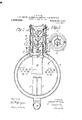
- Fig. 2 is an enlar ed vertical sectional view through the axis of the smoke-stack on the line 22 Fig. 1 looking in the direction of the arrow, showing the return passage which communicates with a pipe leading back to the ash-pit and illustrating the open Specification of Letters Patent.
- Fig. 3 is a sectional View similar to Fig. 2, but showing the parts closed in the smokestack, the section being taken'on line 3-3, Fig. 5.
- Fig. 4 is a horizontal, sectional view on the line 44, Fig. 8 looking downward.
- Fig. 5 is a top plan view of the smokestack.
- a designates the conventional wagon-top boiler having the usual fire-box Z) and tubes 0.
- the ash-pit is shown at d, the smokestack being designated as a whole at e.
- the exhaust nozzles and petticoat pipe are indicated at f and g respectively.
- annular members 2', j, and k Located within the smoke-stack e are a plurality of annular members 2', j, and k that are rigidly secured in place by means of the braces m, n, and 0.
- the brace n secures the annular member 7' to the member is which, in turn, is secured to the smokestack a by means of the brace 0.
- the brace m secures the annular member 2' to the cylindrical member h which, in turn, is secured to the smoke-box 7L
- the annular members are substantially funnel-shaped and are provided with downwardly tapered portions 7) and upwardly extending cylindrical portions 9 that are co-axial with the smokestack.
- a plurality of inverted cone-shaped members 1 which are secured to a vertically movable rod 8, the upper end of which is guided by means of a brace-bar t attached to the lower inner portion of the member is, as shown, having a collar u thereon, its lower end resting upon a cam '12 that is secured to the transversely arranged rock-shaft w that is mounted in the annular ring m which is secured to the smoke-box portion 7& of the boiler.
- the outer end of this rock-shaft is provided with a crank-arm y to which a reach rod 2 is attached that leads back to the cab and is within easy reach of the engineer.
- 2 designates a pair of cams that are also secured to the rock-shaft w and engage the lower edge of the cylindrical sleeve 3, which. surrounds a cylindrical member h located over the opening k of the smoke-box h.
- each of the annular members a, j, and k is provided with a downwardly curving channel 6 which is 10- catedon the under side and forms an upward continuation of the downwardly tapered portions 3) adjacent the part g of the annular member which is immediately below, the purpose 'of which is to cause the heavy particles or 'cinders to be deflected downward into the annular passage-way 7, asshown by the arrow 8.
- the cams 2 have rods 2 connected thereto which, in turn, are connected to the lift ring e? which opens and closes the passages c at the upper end of the passage-way 7.
- the annular members i, j are each provided with a circular or grooved channel 14 which is adjacent the upwardly extending cylindrical part 9. Located over each of these channels is the outlet end of a pipe 15 forconveying water thereto for the purpose of catching an fine particles that may be carried into t e space 7.
- the sleeve 3 is provided with ribs 3 for lessening friction and to prevent sticking.
- the sleeve 3 and the cone-shaped members 1- balance each other when the rod 2 is operated. Thatis to say, when the sleeve 3 is moved upward the cone-shaped members r are permitted to move downward by the cams 2.
- the weight of the sleeve 3 is substantially the same as the members 1'.
- the inverted cone-shaped members 1- serve to deflect the heavy sparks through the openings 13 and the curves 6 deflect them into the passage-way 9.
- the lighter particles and gases pass upward and out of the top of the smoke-stack.
- the inverted cone-shaped members are elevated, as shown in Fig. 3, all of the passages to the top of the smoke-stack are closed and all of the products of combustion pass through the openings 13.
- the sleeve 3 is then in its lowest position and the ring e has closed the opening 6
- the products of combustion are drawn downward through the passages 9 to the pipe 10 by means of the steam escaping from the pipe 12 and into the ash-pit d.
- the gases are purified by means of the spray of water from the pipe 12 rendering the products of combustion in condition to support combustion when passed through the fire-box.
- a spark-arresting and smoke-preventing device the combination with the smoke-stack of a locomotive boiler, the interior portion of which is provided with a cylindrical member located over the opening in the smoke-box, of a rock-shaft extending transversely of the cylindrical member, a cam thereon, an annular member located above the cylindrical member having a downwardly tapering portion, and a sleeve adapted to be operated by the cam to vary the opening between the cylindrical member and the downwardly tapering portion of the annular member.
- cylindrical member having a downwardly tapering portion, and a sleeve adapted to be operated by the cam to vary the opening between the annular member and the cylindrical member, a cone-shaped member operable from the rock-shaft to deflect the products of combustion into the space outside the cylindrical member, and means for conveying the products of'combustion back to the ashpit.
- a spark-arresting and smoke-pre-' venting device the combination with the smoke-stack, of a plurality of annular members located in said smoke-stack and spaced from the inner surface thereof, said members having downwardly tapering'portions and upwardly projecting cylindrical portions, the portion of the annular members between the upper and lower portions thereof being provided with annular grooves, the lower grooves being designed to cause the heavier particles to be thrown outwardly and downwardly into the space between the annular members and the interior of the smoke-stack, means for conveying the products' of combustion back to the ash-pit, and means for cleaning the annular grooves that are adjacent the cylindrical portion of the annular members.
- a spark-arrester and smoke-preventing device for locomotive boilers the combination with a smoke-stack, of a rockshaft located transversely of the same, a cam ,on said rock-shaft, and a vertically movable rod adapted to be operated by the cam on the rock-shaft, a plurality of'cone-shaped members secured to the vertically movable rod, the base portion of said cone-shaped members being upward, and a plurality of annular members having downwardly tapering portions adapted to be engaged by the base portions of the cone-shaped members whereby the products of combustion will be deflected or forced past the closed meeting edges of the tapering portions of the annular members and the cone-shaped members to the space adjacent the inner surface of the smoke-stack, means for conveying the products of combustion back to the ash-pit, and means for purifying the same during their passage.
Description
P. H. COLE. SPARK ARRESTER AND SMOKE PREVENTING DEVICE FOR LOCOMOTIVES.
APPLICATION FILED JAN. 4, 1911.
Patented Sept. 5, 1911.
2 SHEETS-SHEET 1.
iv VENTOR, Frank 15. 6' 0 Z 6,
A TTORNEYS WITNESSES- I I. H. COLE. SPARK ARRESTER AND SMOKE PREVENTING DEVICE FOR LOCOMOTIVES.
APPLICATION FILED JAN. 4, 1911.
1,002,564. 1 Patented Sept. 5,1911.
2 SHEETSSHEBT 2.
C) Q I WITNESSES: INVENTOR,
. jfdfll' E 606 BY 7%. W W A TITORNEYS' FRANK H. COLE, 0F HOLYOKE, MASSACHUSETTS.
SPARK-ARRESTER AND SMOKE-PREVENTING DEVICE FOR LOCOMOTIVES.
To all whom it may concern:
Be it known that T, FRANK H. Conn, a citizen of the United States of America, residing at Holyoke, in the county of Hampden and State of Massachusetts, have invented new and useful Improvements in Spark-Arresters and Smoke-Preventing Devices for Locomotives, of which the following is a specification.
This invention relates to improvements in spark arresters and smoke preventing devices as applied to locomotive boilers.
The object of the invention is to provide means for preventing the live or hot cinders from escaping or flying out of the smokestack of a locomotive during its passage over the road-bed. It sometimes occurs that fires are started by reason of the hot cinders escaping from the stack and falling upon dry leaves or grass adjoining the track. My object, as stated, is to prevent their escape from the smoke-stack.
Broadly, the invention consists in providing the interior portion of the smokestack with a series of annular deflecting members for turning the heavier sparks or cinders downward.
The invention further consists in means for conveying all of the products of com bustion back into the fire-box when the train is passing through a tunnel; also in providing means for increasing the downward draft when the products of combus-v tion are being led back and down into the firebox.
The invention further consists in providing means for purifying the products of combustion so that they can be used again for assistipg combustion in the fire-box and in providing means for preventing the escape of smoke from the smoke-stack.
The invention will be fully described in the bodyof the specification with reference to the drawings, and will be. specificall pointed out in the claims.
In the drawings forming part of this application,-Figure 1 is a longitudinal sectional view through the boiler showing the fire-box, tubes, and the return-pipe from the smoke-stack back to the ash-pit. Fig. 2 is an enlar ed vertical sectional view through the axis of the smoke-stack on the line 22 Fig. 1 looking in the direction of the arrow, showing the return passage which communicates with a pipe leading back to the ash-pit and illustrating the open Specification of Letters Patent.
Application filed January 4., 1911.
Patented nept. 5, 1911.
Serial No. 600,695.
' position of the parts in the smoke-stack.
Fig. 3 is a sectional View similar to Fig. 2, but showing the parts closed in the smokestack, the section being taken'on line 3-3, Fig. 5. Fig. 4 is a horizontal, sectional view on the line 44, Fig. 8 looking downward. Fig. 5 is a top plan view of the smokestack.
Referring to the drawings in detail, a designates the conventional wagon-top boiler having the usual fire-box Z) and tubes 0. The ash-pit is shown at d, the smokestack being designated as a whole at e. The exhaust nozzles and petticoat pipe are indicated at f and g respectively.
Located within the smoke-stack e are a plurality of annular members 2', j, and k that are rigidly secured in place by means of the braces m, n, and 0. The brace n secures the annular member 7' to the member is which, in turn, is secured to the smokestack a by means of the brace 0. The brace m secures the annular member 2' to the cylindrical member h which, in turn, is secured to the smoke-box 7L The annular members are substantially funnel-shaped and are provided with downwardly tapered portions 7) and upwardly extending cylindrical portions 9 that are co-axial with the smokestack. Arranged below the downwardly tapered portions p and adapted to engage the lower edges of the same are a plurality of inverted cone-shaped members 1 which are secured to a vertically movable rod 8, the upper end of which is guided by means of a brace-bar t attached to the lower inner portion of the member is, as shown, having a collar u thereon, its lower end resting upon a cam '12 that is secured to the transversely arranged rock-shaft w that is mounted in the annular ring m which is secured to the smoke-box portion 7& of the boiler. The outer end of this rock-shaft is provided with a crank-arm y to which a reach rod 2 is attached that leads back to the cab and is within easy reach of the engineer. 2 designates a pair of cams that are also secured to the rock-shaft w and engage the lower edge of the cylindrical sleeve 3, which. surrounds a cylindrical member h located over the opening k of the smoke-box h.
When the cone-shaped members r are dis engaged from the downwardly tapered portions 7), as shown in Fig. 2, the sleeve 3 projects above the upper edge 5 of the cylindrical member it. Each of the annular members a, j, and k is provided with a downwardly curving channel 6 which is 10- catedon the under side and forms an upward continuation of the downwardly tapered portions 3) adjacent the part g of the annular member which is immediately below, the purpose 'of which is to cause the heavy particles or 'cinders to be deflected downward into the annular passage-way 7, asshown by the arrow 8. When the coneshaped members 1' engage the downwardly tapered portions p the cinders and smoke are all deflected downward into the annular passage-way 7 which is inscommunication with a pipe or passage-way 9 extending forward from the smoke-stack e and down around the front end of the smoke-box k and on the opposite-sides of the same, to a pipe 10 which communicates with the ashpit d by means of the opening 11. Located within the pipe 10 is a plpe 12 for the purpose of conveying water in spray form therethrough and whereby the gaseous products of combustion are purified and washed before being drawn into the ash-pit by means of the steam-jet shown at. 12 when the locomotive is passing through a tunnel, or in cities where the smoke laws are in force. When the cone-shaped members 1- are disengaged from the downwardly tapered portions p, as shown in Fig. 2, the
lighter particles, or the gaseous products of combustion, will pass dlrectly upward through the smoke-stack to the atmosphere,
but the heavier particles, or those that are liable to cause fire, will be thrown outward or fall downward through the passageways 13 into the annular passage-way 7, and from there will be carried backward into the ash-pit d.
The cams 2 have rods 2 connected thereto which, in turn, are connected to the lift ring e? which opens and closes the passages c at the upper end of the passage-way 7.
It will be noticed in Fig. 2 that when the rock-shaft w is operatedso as to lower the cone-shaped members 0, the sleeve 3 and ring a will be elevated by means of the cams 2, and when the cone-shaped members 1- are elevated, the sleeve 3 and ring e will bendepressed or lowered, thus widening the passage-way between the downward y tapered portions (p of the annularmember i and the upper e go of the cylindrical part 4, as clearly shown in Fig. 3. Or, in other words, 'the sleeve 3 and the cone-shaped members 1- move in opposite directions.
The annular members i, j, are each provided with a circular or grooved channel 14 which is adjacent the upwardly extending cylindrical part 9. Located over each of these channels is the outlet end of a pipe 15 forconveying water thereto for the purpose of catching an fine particles that may be carried into t e space 7. The pipe 15,
therefore, affords means for washing and cleaning these channels. The sleeve 3 is provided with ribs 3 for lessening friction and to prevent sticking.
From the arrangement of the cams on the shaft w, the sleeve 3 and the cone-shaped members 1- balance each other when the rod 2 is operated. Thatis to say, when the sleeve 3 is moved upward the cone-shaped members r are permitted to move downward by the cams 2. The weight of the sleeve 3 is substantially the same as the members 1'.
In operation, considering the inverted cone-shaped members r in a lowered position, that is, as shown in Fig. 2, the aseous products of combustion will escape irectly upward through the smoke-stack to the atmosphere, part going, however, through the openings 13 to the passage 6 under the ring e The heavy cinders, as they strike the downwardly curved channels 6, will be arrested or deflected downward into the passage-way 7, and then carried into the pipe 10 where they may be blown to the ash-pit by means of the steam connection 16.
16 indicates a clean-out door. In this figure, the sleeve 3 is elevated above the upper end of the part it.
The inverted cone-shaped members 1- serve to deflect the heavy sparks through the openings 13 and the curves 6 deflect them into the passage-way 9. The lighter particles and gases pass upward and out of the top of the smoke-stack.
WVhen the inverted cone-shaped members are elevated, as shown in Fig. 3, all of the passages to the top of the smoke-stack are closed and all of the products of combustion pass through the openings 13. The sleeve 3 is then in its lowest position and the ring e has closed the opening 6 Now the products of combustion are drawn downward through the passages 9 to the pipe 10 by means of the steam escaping from the pipe 12 and into the ash-pit d. The gases are purified by means of the spray of water from the pipe 12 rendering the products of combustion in condition to support combustion when passed through the fire-box.
What I claim, is
1. In a spark-arresting and smoke-preventing device, the combination with the smoke-stack of a locomotive boiler, the interior portion of which is provided with a cylindrical member located over the opening in the smoke-box, of a rock-shaft extending transversely of the cylindrical member, a cam thereon, an annular member located above the cylindrical member having a downwardly tapering portion, and a sleeve adapted to be operated by the cam to vary the opening between the cylindrical member and the downwardly tapering portion of the annular member.
cam thereon, an annular member located,
above the cylindrical member having a downwardly tapering portion, and a sleeve adapted to be operated by the cam to vary the opening between the annular member and the cylindrical member, a cone-shaped member operable from the rock-shaft to deflect the products of combustion into the space outside the cylindrical member, and means for conveying the products of'combustion back to the ashpit.
3. In a spark-arresting and smoke-pre-' venting device, the combination with the smoke-stack, of a plurality of annular members located in said smoke-stack and spaced from the inner surface thereof, said members having downwardly tapering'portions and upwardly projecting cylindrical portions, the portion of the annular members between the upper and lower portions thereof being provided with annular grooves, the lower grooves being designed to cause the heavier particles to be thrown outwardly and downwardly into the space between the annular members and the interior of the smoke-stack, means for conveying the products' of combustion back to the ash-pit, and means for cleaning the annular grooves that are adjacent the cylindrical portion of the annular members. 1
4. In a spark-arrester and smoke-preventing device for locomotive boilers, the combination with a smoke-stack, of a rockshaft located transversely of the same, a cam ,on said rock-shaft, and a vertically movable rod adapted to be operated by the cam on the rock-shaft, a plurality of'cone-shaped members secured to the vertically movable rod, the base portion of said cone-shaped members being upward, and a plurality of annular members having downwardly tapering portions adapted to be engaged by the base portions of the cone-shaped members whereby the products of combustion will be deflected or forced past the closed meeting edges of the tapering portions of the annular members and the cone-shaped members to the space adjacent the inner surface of the smoke-stack, means for conveying the products of combustion back to the ash-pit, and means for purifying the same during their passage.
FRANK, H. COLE.
Witnesses R. I. (borrow,
HARRY W. BOWEN.
Priority Applications (1)
| Application Number | Priority Date | Filing Date | Title |
|---|---|---|---|
| US60069511A US1002564A (en) | 1911-01-04 | 1911-01-04 | Spark-arrester and smoke-preventing device for locomotives. |
Applications Claiming Priority (1)
| Application Number | Priority Date | Filing Date | Title |
|---|---|---|---|
| US60069511A US1002564A (en) | 1911-01-04 | 1911-01-04 | Spark-arrester and smoke-preventing device for locomotives. |
Publications (1)
| Publication Number | Publication Date |
|---|---|
| US1002564A true US1002564A (en) | 1911-09-05 |
Family
ID=3070884
Family Applications (1)
| Application Number | Title | Priority Date | Filing Date |
|---|---|---|---|
| US60069511A Expired - Lifetime US1002564A (en) | 1911-01-04 | 1911-01-04 | Spark-arrester and smoke-preventing device for locomotives. |
Country Status (1)
| Country | Link |
|---|---|
| US (1) | US1002564A (en) |
Cited By (3)
| Publication number | Priority date | Publication date | Assignee | Title |
|---|---|---|---|---|
| US3485191A (en) * | 1968-02-08 | 1969-12-23 | John R Christman | Heat generator |
| US3729901A (en) * | 1971-07-20 | 1973-05-01 | D Jackson | Emission and pollutant recovery process and apparatus |
| US3756170A (en) * | 1971-04-30 | 1973-09-04 | Care Inc | Anti-pollution liquid waste burning incinerator |
-
1911
- 1911-01-04 US US60069511A patent/US1002564A/en not_active Expired - Lifetime
Cited By (3)
| Publication number | Priority date | Publication date | Assignee | Title |
|---|---|---|---|---|
| US3485191A (en) * | 1968-02-08 | 1969-12-23 | John R Christman | Heat generator |
| US3756170A (en) * | 1971-04-30 | 1973-09-04 | Care Inc | Anti-pollution liquid waste burning incinerator |
| US3729901A (en) * | 1971-07-20 | 1973-05-01 | D Jackson | Emission and pollutant recovery process and apparatus |
Similar Documents
| Publication | Publication Date | Title |
|---|---|---|
| US1002564A (en) | Spark-arrester and smoke-preventing device for locomotives. | |
| US223403A (en) | Spark-arrester | |
| US851494A (en) | Spark-arrester. | |
| US328962A (en) | Half to i | |
| US378762A (en) | Perry j | |
| US603378A (en) | Paul hagemann and heinrich pasler | |
| US537048A (en) | Spark-arrester | |
| US133436A (en) | Improvement in spark-arresters | |
| US336311A (en) | Territory | |
| US214966A (en) | Improvement in spark-arresters | |
| US115153A (en) | Improvement in smoke-stacks for lqcomqtives | |
| US228442A (en) | Spark-arrester | |
| US467051A (en) | Spark-arrester | |
| US516940A (en) | Spark-arrester | |
| US163568A (en) | Improvement in spark-arresters for locomotives | |
| US6637A (en) | Locomotive spark-arrester and smoke-conductor | |
| US429138A (en) | Spark-arrester | |
| US433647A (en) | Island | |
| US792209A (en) | Spark-arrester. | |
| US346012A (en) | Paul h | |
| US934767A (en) | Spark-arresting appliance for lignite-burning locomotives. | |
| US2901A (en) | Spakk-akrester | |
| US593572A (en) | Locomotive smoke-stack | |
| US459179A (en) | Half to frank dekum | |
| US214676A (en) | Improvement in smoke-condenser and spark-extinguisher |