CROSS-REFERENCE TO RELATED APPLICATIONS
This application claims priority under 35 U.S.C. § 119 to Japanese Patent Application Nos. 2013-141967, filed Jul. 5, 2013, and 2014-011235, filed Jan. 24, 2014. The entire disclosures of Japanese Patent Application Nos. 2013-141967 and 2014-011235 are hereby incorporated herein by reference.
BACKGROUND
Field of the Invention
This invention generally relates to a bicycle control system. More specifically, the present invention relates to a bicycle control system.
Background Information
Conventionally, a control apparatus that can electrically control a transmission device such as a front derailleur, or a suspension has been known (for example, Japanese Laid-Open Patent Publication No. 2013-121834). Such a control apparatus can operate a transmission device and the like by a wireless signal.
SUMMARY
In order to drive an electric drive device including a transmission device or a suspension as described above, a battery is incorporated into each electric drive device so as to supply electric power to each electric drive device. However, in a case where a battery is incorporated into each electric drive device, the timings for replacing the batteries are different since there is a difference in power consumption between each of the electric drive devices. Therefore, the maintenance of power supply becomes laborious.
The object of the present invention is to simplify the maintenance of power supply in a bicycle control system that includes an electric drive device operated in response to a wireless signal.
According to a first aspect of the present invention, a bicycle control system comprises a first power supply, a plurality of electric drive devices, and an operating apparatus. Each electric drive device is electrically coupled to the first power supply to receive electric power supplied from the first power supply. The operating apparatus wirelessly operates the electric drive devices by wireless signals.
With this configuration, the plurality of electric drive devices are connected to the single first power supply, and electric power is supplied from this first power supply. Therefore, even when the electric drive devices are configured to be operated in response to a wireless signal, the labor for replacing or charging the battery can be reduced.
Preferably, the operating apparatus is electrically coupled to the first power supply to receive electric power supplied from the first power supply. With this configuration, since electric power is supplied from the first power supply to the operating apparatus as well, the labor for replacing or charging the battery can further be reduced.
The bicycle control system may further comprise a second power supply. The second power supply is electrically coupled to the operating apparatus to supply electric power to the operating apparatus. By providing a power supply for the operating apparatus separately from the power supply for the plurality of electric drive devices, the flexibility of the arrangement can be improved.
Preferably, the electric drive devices and the first power supply are configured to be attachable to a frame main body of a bicycle. Also, the operating apparatus and the second power supply are configured to be attachable to a movable member that is movable relative to the frame main body. With this configuration, since there is no cable or the like that extends over the frame main body and the movable member, the movable member can be moved more smoothly relative to the frame main body.
Preferably, the bicycle control system further comprises at least one first wireless communication unit. The at least one first wireless communication unit is operatively connected to the electric drive devices. With this configuration, since the electric drive devices share a single first wireless communication unit, the cost can be reduced.
Preferably, the at least one first wireless communication unit is configured to be attachable in a vicinity of a stem of a frame main body of a bicycle. In a case where the operating apparatus is attached to a stem or a handlebar, the wireless communication distance can be shortened so as to reduce communication errors by attaching the first wireless communication unit in the vicinity of the stem.
The first power supply may be retained in a retaining member that is configured to be attached to the main body of the bicycle. In this case, the at least one first wireless communication unit may be attached to the retaining member.
The at least one first wireless communication unit may be disposed in the first power supply.
The at least one first wireless communication unit may be included as a part of one of the electric drive devices.
Preferably, the first power supply is connected to each electric drive device through an electric power line. The at least one first wireless communication unit is configured to communicate with each of the electric drive devices through the electric power line.
Preferably, the operating apparatus has a second wireless communication unit that transmits a wireless signal to the at least one first wireless communication unit to operate the electric drive device. Since a wireless signal can be transmitted by the single second wireless communication unit, the amount of power consumption can be reduced.
The operating apparatus may include a plurality of operating devices. The at least one second wireless communication unit transmits wireless signals to the at least one first wireless communication unit in response to operation of the operating devices.
The operating apparatus may include a plurality of operating devices and have the at least one second wireless communication unit includes a separate second wireless communication unit for each of the operating devices.
The at least one first wireless communication unit includes a separate first wireless communication unit for each of the electric drive devices. The at least one second wireless communication unit communicates with the separate first wireless communication units. Each first wireless communication unit receives a wireless signal from the corresponding second wireless communication unit. In this case, wireless signals can be transmitted to the plurality of electric drive devices at the same time, and the plurality of electric drive devices can receive the wireless signals at the same time. Therefore, a time lag to an operation of the electric drive device in response to an operation of the operating apparatus can be controlled.
The operating apparatus may include a plurality of operating devices, and the at least one second wireless communication unit transmits wireless signals in response to operation of the operating device.
The first power supply may include one of a primary battery and a secondary battery.
The second power supply may include one of a primary battery and a secondary battery.
The electric drive devices can include at least two of a front transmission device, a rear transmission device, a front suspension device, a rear suspension device and a seat post lifting device.
The operating apparatus may include an operating device. The operating device can include at least one of a gear shifting operating device, a suspension operating device, and a seat post operating device.
According to the present invention, a bicycle control system that can simplify the maintenance of power supply can be provided even if an electric drive device is configured to be operated in response to a wireless signal.
Also other objects, features, aspects and advantages of the disclosed bicycle control system will become apparent to those skilled in the art from the following detailed description, which, taken in conjunction with the annexed drawings, discloses several illustrative embodiment of the bicycle control system.
BRIEF DESCRIPTION OF THE DRAWINGS
Referring now to the attached drawings which form a part of this original disclosure:
FIG. 1 is a side elevational view of a bicycle that is equipped with a bicycle control system in accordance with a first embodiment.
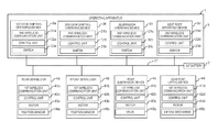
FIG. 2 is a block diagram of a bicycle control system in accordance with the first embodiment.
FIG. 3 is a block diagram of a bicycle control system in accordance with a second embodiment.
FIG. 4 is a block diagram of a bicycle control system in accordance with a third embodiment.
FIG. 5 is a side elevational view of a bicycle that is equipped with a bicycle control system in accordance with the third embodiment.
FIG. 6 is a block diagram of a bicycle control system in accordance with a fourth embodiment.
FIG. 7 is a side elevational view of a bicycle that is equipped with a bicycle control system in accordance with a seventh modified example.
FIG. 8 is a block diagram of a bicycle control system in accordance with an eighth modified example.
FIG. 9 is a block diagram of a bicycle control system in accordance with a ninth modified example, a tenth modified example, and an eleventh modified example.
DETAILED DESCRIPTION OF EMBODIMENTS
Selected embodiments will now be explained with reference to the drawings. It will be apparent to those skilled in the bicycle field from this disclosure that the following descriptions of the embodiments are provided for illustration only and not for the purpose of limiting the invention as defined by the appended claims and their equivalents.
Referring initially to FIG. 1, a bicycle 10 is illustrated that is equipped with a bicycle control system 12 in accordance with a first embodiment.
First Embodiment
As shown in FIG. 1, a bicycle 100 to which a bicycle control system 1 according to a first embodiment is applied has a frame main body 101, a stem (one example of the movable member) 102, a handlebar (one example of the movable member) 103, and a seat post 104.
As shown in FIG. 2, the bicycle control system 1 has a first battery (one example of the first power supply) 2, an operating apparatus 3, and a plurality of electric drive devices 4 a-4 d. The plurality of electric drive devices 4 a-4 d are, for example, a rear derailleur (one example of the rear transmission device) 4 a, a front derailleur (one example of the front transmission device) 4 b, a rear suspension device 4 c, and a seat post lifting device 4 d. Each of the electric drive devices 4 a-4 d is attached to the frame main body 101.
The plurality of electric drive devices 4 a-4 d have first wireless communication unit s 41 a-41 d, respectively. Specifically, the rear derailleur 4 a has the first wireless communication unit 41 a. The rear derailleur 4 a also has a control unit 42 a and a motor 43 a in addition to the first wireless communication unit 41 a. In the rear derailleur 4 a, a gear shifting operation is executed by controlling the motor 43 a by the control unit 42 a based on a wireless signal received by the first wireless communication unit 41 a. The rear derailleur 4 a also has a position sensor 44 a. The control unit 42 a can stop a chain guide plate at a position that corresponds to each gear shifting stage based on detection of the position sensor 44 a. The control unit 42 a transmits the position that corresponds to each gear shifting stage detected by the position sensor 44 a to a second wireless communication unit 31 a of a first gear shifting operating device 3 a described below through the first wireless communication unit 41 a. For example, in a case in which a display device is provided on or connected to the operating apparatus 3, the display device may display information on the position that corresponds to each gear shifting stage received by the second wireless communication unit 31 a. The display device may be implemented, for example, by a cycle computer.
The front derailleur 4 b has the first wireless communication unit 41 b. The front derailleur 4 b also has a control unit 42 b and a motor 43 b in addition to the first wireless communication unit 41 b. In the front derailleur 4 b, a gear shifting operation is executed by controlling the motor 43 b by the control unit 42 b based on a wireless signal received by the first wireless communication unit 41 b. The front derailleur 4 b also has a position sensor 44 b. The control unit 42 b can stop a chain guide plate at a position that corresponds to each gear shifting stage based on detection of the position sensor 44 b. The control unit 42 b transmits the position that corresponds to each gear shifting stage detected by the position sensor 44 b to a second wireless communication unit 31 b of a second gear shifting operating device 3 b described below through the first wireless communication unit 41 b. For example, in a case in which a display device is provided on or connected to the operating apparatus 3, the display device may display information on the position that corresponds to each gear shifting stage received by the second wireless communication unit 31 b.
The rear suspension device 4 c has the first wireless communication unit 41 c. The rear suspension device 4 c also has a control unit 42 c, a motor 43 c, and a valve 45 c in addition to the first wireless communication unit 41 c. In the rear suspension device 4 c, the control unit 42 c controls the valve 45 c by controlling the motor 43 c based on a wireless signal received by the first wireless communication unit 41 c. An operation state of the rear suspension device 4 c can be changed by controlling the valve 45 c. For example, the rear suspension device 4 c can be put in a free state in which the rear suspension device 4 c can expand or contract or in a lock state in which the rear suspension device 4 c cannot expand nor contract as the operation state. For example, the rear suspension device 4 c can also be put in a hard state or a soft state in the free state. The rear suspension device 4 c expands or contracts slowly in the hard state compared to in the soft state. The rear suspension device 4 c may have a sensor that detects the state of the valve 45. The rear suspension device 4 c may transmit information on the valve 45 c detected by this sensor to a second wireless communication unit 31 c of a suspension operating device 3 c described below through the first wireless communication unit 41 c. For example, in a case in which a display device is provided on or connected to the operating apparatus 3, the display device may display information on the valve 45 c, that is, information on the rear suspension device 4 c received by the second wireless communication unit 31 c.
The seat post lifting device 4 d has the first wireless communication unit 41 d. The seat post lifting device 4 d also has a control unit 42 d, a motor 43 d, and a lifting mechanism 45 d in addition to the first wireless communication unit 41 d. In the seat post lifting device 4 d, the control unit 42 d controls the lifting mechanism 45 d by controlling the motor 43 d based on a wireless signal received by the first wireless communication unit 41 d. For example, the seat post 104 is constructed of two cylindrical sections that can expand or contract. For example, the lifting mechanism 45 d includes a ball screw and a nut. The nut is moved by driving rotation of the ball screw by the motor 43. The motor 43 d and the ball screw are disposed in one of the cylindrical sections, and the nut is coupled to the other of cylindrical sections. With this configuration, the nut is moved along the ball screw by driving the motor 43 so as to expand or contract the seat post 104. The seat post lifting device 4 d may have a sensor that detects the height of the seat post 104. The seat post lifting device 4 d may transmit information on the height of the seat post 104 detected by this sensor to a second wireless communication unit 31 d of a seat post operating device 3 d described below through the first wireless communication unit 41 d. For example, in a case in which a display device is provided on or connected to the operating apparatus 3, the display device may display information on the height of the seat post 104 received by the second wireless communication unit 31 d.
The operating apparatus 3 has operating devices 3 a-3 d that correspond to the electric drive devices 4, respectively. Specifically, the operating apparatus 3 has the first gear shifting operating device 3 a, the second gear shifting operating device 3 b, the suspension operating device 3 c, and the seat post operating device 3 d. The operating devices 3 a-3 d are attached, for example, to the handlebar 103.
The first gear shifting operating device 3 a operates the rear derailleur 4 a by a wireless signal. The first gear shifting operating device 3 a has the second wireless communication unit 31 a. The first gear shifting operating device 3 a has a control unit 32 a and a switch 33 a in addition to the second wireless communication unit 31 a. By operating the switch 33 a of the first gear shifting operating device 3 a, the control unit 32 a controls the second wireless communication unit 31 a, and a wireless signal is transmitted from the second wireless communication unit 31 a. The first wireless communication unit 41 a of the rear derailleur 4 a receives the wireless signal transmitted from the second wireless communication unit 31 a of the first gear shifting operating device 3 a. The switch 33 a of the first gear shifting operating device 3 a may be constructed of a single member, or may be constructed of a plurality of members. For example, the switch 33 a is made of two members, in which a gear shifting operation of the rear derailleur 4 a is executed to accelerate the rear derailleur 4 a when operating one of the members and a gear shifting operation of the rear derailleur 4 a is executed to decelerate the rear derailleur 4 a when operating the other one of the members.
The second gear shifting operating device 3 b operates the front derailleur 4 b by a wireless signal. The second gear shifting operating device 3 b has the second wireless communication unit 31 b. The second gear shifting operating device 3 b has a control unit 32 b and a switch 33 b in addition to the second wireless communication unit 31 b. By operating the switch 33 b of the second gear shifting operating device 3 b, the control unit 32 b controls the second wireless communication unit 31 b, and a wireless signal is transmitted from the second wireless communication unit 31 b. The first wireless communication unit 41 b of the front derailleur 4 b receives the wireless signal transmitted from the second wireless communication unit 31 b of the second gear shifting operating device 3 b. The switch 33 b of the second gear shifting operating device 3 b may be constructed of a single member, or may be constructed of a plurality of members. For example, the switch 33 b is made of two members, in which a gear shifting operation of the front derailleur 4 b is executed to accelerate the front derailleur 4 b when operating one of the members and a gear shifting operation of the front derailleur 4 b is executed to decelerate the front derailleur 4 b when operating the other one of the members.
The suspension operating device 3 c operates the rear suspension device 4 c by a wireless signal. The suspension operating device 3 c has the second wireless communication unit 31 c. The suspension operating device 3 c has a control unit 32 c and a switch 33 c in addition to the second wireless communication unit 31 c. By operating the switch 33 c of the suspension operating device 3 c, the control unit 32 c controls the second wireless communication unit 31 c, and a wireless signal is transmitted from the second wireless communication unit 31 c. The first wireless communication unit 41 c of the rear suspension device 4 c receives the wireless signal transmitted from the second wireless communication unit 31 c of the suspension operating device 3 c. The switch 33 c of the suspension operating device 3 c may be constructed of a single member, or may be constructed of a plurality of members. For example, in a case in which the switch 33 c is made of two members, the rear suspension device 4 c is put in the free state when operating one of the members and the rear suspension device 4 c is put in the lock state when operating the other one of the members. Also, in a case in which the switch 33 c is made of a single member, the state of the rear suspension device 4 c may be switched between the free state and the lock state every time the switch is operated.
The seat post operating device 3 d operates the seat post lifting device 4 d by a wireless signal. The seat post operating device 3 d has the second wireless communication unit 31 d. The seat post operating device 3 d has a control unit 32 d and a switch 33 d in addition to the second wireless communication unit 31 d. By operating the switch 33 d of the seat post operating device 3 d, the control unit 32 d controls the second wireless communication unit 31 d, and a wireless signal is transmitted from the second wireless communication unit 31 d. The first wireless communication unit 41 d of the seat post lifting device 4 d receives the wireless signal transmitted from the second wireless communication unit 31 d of the seat post operating device 3 d. The switch 33 d of the seat post operating device 3 d may be constructed of a single member, or may be constructed of a plurality of members. For example, the switch 33 d is made of two members, in which the seat post 104 expands when operating one of the members and the seat post 104 contracts when operating the other one of the members.
The first battery 2 is connected to the operating devices 3 a-3 d and the electric drive devices 4 a-4 d, and supplies electric power to the operating devices 3 a-3 d and the electric drive devices 4 a-4 d. The first battery 2 is provided as a separate member from the operating devices 3 a-3 d and the electric drive devices 4 a-4 d.
The first battery 2 is connected to the operating devices 3 a-3 d and the electric drive devices 4 a-4 d, through an electric power line 21. For example, the electric power line 21 extending from the first battery 2 is branched so as to be connected to the operating devices 3 a-3 d and the electric drive devices 4 a-4 d. Electric power is supplied to the operating devices 3 a-3 d and the electric drive devices 4 a-4 d through the electric power line 21. For example, electric power is supplied as direct voltage. The first battery 2 is attached to the frame main body 101. The first battery 2 may be a primary battery (i.e., a portable voltaic cell that is not rechargeable), or may be a secondary battery (i.e., a portable voltaic cell that is rechargeable).
Although the branched electric power line 21 is illustrated in FIG. 2, the operating devices 3 a-3 d may be connected to the first battery 2 through separate electric power lines. The electric drive devices 4 a-4 d may be connected to the first battery 2 through separate electric power lines. Alternatively, the first battery 2 may be connected to any one of the operating devices 3 a-3 d of the operating apparatus 3 by the single electric power line 21 only, and the one of the operating devices 3 a-3 d, to which the electric power line 21 is connected, may be connected to the other operating devices of the operating devices 3 a-3 d by the electric power line 21. Furthermore, electric power may be supplied from the first battery 2 by connecting the electric drive devices 4 a-4 d in a row through separate electric power lines.
Second Embodiment
As shown in FIG. 3, a bicycle control system 10 according to a second embodiment is different from the bicycle control system 1 according to the above-described first embodiment in that the bicycle control system 10 further comprises a second battery (one example of the second power supply) 5. The configuration other than the presence of the second battery 5 is basically the same as in the bicycle control system 1 according to the above-described first embodiment. Therefore, the same reference numerals are assigned to the parts that are configured in the substantially same manner, and overlapping explanations are omitted.
The second battery 5 is provided as a separate member from the operating devices 3 a-3 d. The second battery 5 is connected to the operating devices 3 a-3 d, and supplies electric power to the operating devices 3 a-3 d in a wired manner. The second battery 5 is connected to the operating devices 3 a-3 d through an electric power line 23. For example, the electric power line 23 extending from the second battery 5 is branched so as to be connected to the operating devices 3 a-3 d. Electric power is supplied to the operating devices 3 a-3 d through the electric power line 23. For example, electric power is supplied as direct voltage. The second battery 5 is attached to the stem 102 or the handlebar 103. The first battery 2 may be a primary battery, or may be a secondary battery. Here, the first battery 2 is connected only to the electric drive devices 4 a-4 d and is not connected to the operating devices 3 a-3 d. The operating devices 3 a-3 d may be connected to the second battery 5 through separate electric power lines. Electric power may be supplied from the second battery 5 by connecting the operating devices 3 a-3 d in a row through separate electric power lines.
Third Embodiment
As shown in FIG. 4, a bicycle control system 11 according to a third embodiment is different from the bicycle control system 1 according to the first embodiment in that the bicycle control system 11 further comprises the second battery 5 and the electric drive devices 4 a-4 d share a single first wireless communication unit 41. The configuration other than these differences is basically the same as in the bicycle control system 1 according to the above-described first embodiment. Therefore, the same reference numerals are assigned to the parts that are configured in the substantially same manner, and overlapping explanations are omitted. Also, the configuration of the second battery 5 is basically the same as in the bicycle control system 10 according to the above-described second embodiment. Therefore, the same reference numerals are assigned to the parts that are configured in the substantially same manner, and overlapping explanations are omitted.
In the bicycle control system 1 according to the above-described first embodiment, each electric drive device has the first wireless communication unit. Specifically, the bicycle control system 1 according to the first embodiment has the first wireless communication unit s whose number is the same as that of the electric drive devices. In contrast, in the bicycle control system 11 according to the third embodiment, the electric drive devices 4 a-4 d share the single first wireless communication unit 411. A cable 46 extending from the single first wireless communication unit 41 is branched so as to be connected to the electric drive devices 4 a-4 d. The first wireless communication unit 41 is attached to the frame main body 101. Preferably, the first wireless communication unit 41 is attached in the vicinity of the stem 102 of the frame main body 101 (see FIG. 5).
The first wireless communication unit 41 receives a wireless signal transmitted from the first gear shifting operating device 3 a, and the control unit 42 a of the rear derailleur 4 a controls the motor 43 a so as to execute a gear shifting operation based on the wireless signal.
The first wireless communication unit 41 receives a wireless signal transmitted from the second gear shifting operating device 3 b, and the control unit 42 b of the front derailleur 4 b controls the motor 43 b so as to execute a gear shifting operation based on the wireless signal.
The first wireless communication unit 41 receives a wireless signal transmitted from the suspension operating device 3 c, and the control unit 42 c of the rear suspension device 4 c controls the motor 43 c based on the wireless signal. The motor 43 c controls the valve 45 c so as to change the operation state of the rear suspension device 4 c.
The first wireless communication unit 41 receives a wireless signal transmitted from the seat post operating device 3 d, and the control unit 42 d of the seat post lifting device 4 d controls the motor 43 d so as to change the height of the seat post 104 based on the wireless signal.
Fourth Embodiment
As shown in FIG. 6, a bicycle control system 12 according to a fourth embodiment is different from the bicycle control system 1 according to the first embodiment in that the bicycle control system 12 further comprises the second battery 5, the electric drive devices 4 a-4 d share the single first wireless communication unit 41, and the operating devices 3 a-3 d share a single second wireless communication unit 31. The configuration other than these differences is basically the same as in the bicycle control system 1 according to the above-described first embodiment. Therefore, the same reference numerals are assigned to the parts that are configured in the substantially same manner, and overlapping explanations are omitted. Also, the configuration of the second battery 5 is basically the same as in the bicycle control system 10 according to the above-described second embodiment. Therefore, the same reference numerals are assigned to the parts that are configured in the substantially same manner, and overlapping explanations are omitted. Furthermore, the sharing of the first wireless communication unit 41 by the electric drive devices 4 a-4 d has the same configuration as in the bicycle control system 11 according to the above-described third embodiment. Therefore, the same reference numerals are assigned to the parts that are configured in the substantially same manner, and overlapping explanations are omitted.
In the bicycle control system 1 according to the above-described first embodiment, each operating device has the second wireless communication unit. Specifically, the bicycle control system 1 according to the first embodiment has the second wireless communication unit s whose number is the same as that of the operating devices. In contrast, in the bicycle control system 12 according to the fourth embodiment, the operating devices 3 a-3 d share the single second wireless communication unit 31. A cable 36 extending from the single second wireless communication unit 31 is branched so as to be connected to the corresponding operating devices 3 a-3 d, respectively. In this case, the second wireless communication unit 31 is attached to the stem 102 or the handlebar 103.
When operating the first gear shifting operating device 3 a, a wireless signal is transmitted from the second wireless communication unit 31, and the wireless signal is received by the first wireless communication unit 41. The control unit 42 a of the rear derailleur 4 a controls the motor 43 a so as to execute a gear shifting operation based on the received wireless signal.
When operating the second gear shifting operating device 3 b, a wireless signal is transmitted from the second wireless communication unit 31, and the wireless signal is received by the first wireless communication unit 41. The control unit 42 b of the front derailleur 4 b controls the motor 43 b so as to execute a gear shifting operation based on the received wireless signal.
When operating the suspension operating device 3 c, a wireless signal is transmitted from the second wireless communication unit 31, and the wireless signal is received by the first wireless communication unit 41. The control unit 42 c of the rear suspension device 4 c controls the motor 43 c based on the received wireless signal. The motor 43 c controls the valve 45 c so as to change the operation state of the rear suspension device 4 c.
When operating the seat post operating device 3 d, a wireless signal is transmitted from the second wireless communication unit 31, and the wireless signal is received by the first wireless communication unit 41. The control unit 42 d of the seat post lifting device 4 d controls the motor 43 d so as to change the height of the seat post 104 based on the received wireless signal.
Although the embodiments of the present invention have been presented heretofore, the present invention is not limited to the embodiments and various modifications can be made without departing from the scope of the invention.
Modified Example 1
Although the first battery 2 is shown as an example of the first power supply, the present invention is not limited to this. For example, a dynamo can be used as the first power supply. In the same manner, a dynamo can be used as the second power supply. As the dynamo, a hub dynamo provided on a hub of a front wheel or a rear wheel of a bicycle, or a block dynamo that generates electric power by contacting a rim of a front wheel or a rim of a rear wheel can be used.
Modified Example 2
The third and fourth embodiments have configurations that include the first battery 2 and the second battery 5. In the third and fourth embodiments, however, electric power may be supplied from the first battery 2 to the operating devices 3 a-3 d of the operating apparatus 3 in a wired manner without having the second battery 5.
Modified Example 3
In a case where the bicycle control system according to the first embodiment further includes a front suspension device as the electric drive device, electric power may be supplied from the first battery 2 to the front suspension device. In a case where the bicycle control system according to the second to fourth embodiments further includes a front suspension device as the electric drive device, electric power may be supplied from the second battery 5 to the front suspension device.
Modified Example 4
The above-described embodiments include the four electric drive devices 4 a-4 d. However, the number of the electric drive devices is not limited as long as at least two electric drive devices are included. Also, the above-described embodiments include the four operating devices 3 a-3 d. However, one operating device is sufficient, and the number of the operating devices is not limited.
Modified Example 5
In the first embodiment, the first battery 2 is provided as a separate member from the operating devices 3 a-3 d and the electric drive devices 4 a-4 d. However, the first battery 2 may be provided integrally with any one of the operating devices 3 a-3 d and the electric drive devices 4 a-4 d.
Modified Example 6
In the second to fourth embodiments, the first battery 2 may be provided integrally with any one of the operating devices 3 a-3 d and the electric drive devices 4 a-4 d, and the second battery 5 may be provided integrally with any one of the operating devices 3 a-3 d.
Modified Example 7
In the third and fourth embodiments, the first wireless communication unit 41 is attached in the vicinity of the stem 102 of the frame main body 101. However, the present invention is not limited to this. For example, as shown in FIG. 7, the first battery 2 is retained in a retaining member 106 which is attached to the main body of the bicycle. The first battery 2 may be retained in the retaining member 106 in a detachable manner. The first wireless communication unit 41 is attached to the retaining member 106. Alternatively, the first wireless communication unit 41 may be disposed in the first battery 2. In this case, the first wireless communication unit 41 can be detached from the retaining member 106 together with the first battery 2. In the present invention, the main body of the bicycle may include the frame main body 101, the seat post 104, a saddle 105, a basket (not shown in the drawings), and the like.
Modified Example 8
In the third and fourth embodiments, the first wireless communication unit 41 is provided as a separate member from the electric drive devices 4 a-4 d. However, the present invention is not limited to this. For example, as shown in FIG. 8, the first wireless communication unit 41 may be included in any one of the electric drive devices 4 a-4 d.
Modified Example 9
In the third and fourth embodiments, the first wireless communication unit 41 can communicate with the electric drive devices 4 a-4 d through the cable 46. However, the present invention is not limited to this. For example, as shown in FIG. 9, the first wireless communication unit 41 may be able to communicate with the electric drive devices 4 a-4 d through the electric power line 21. That is, the first wireless communication unit 41 may be able to communicate with the electric drive devices 4 a-4 d through power line communication (PLC).
Modified Example 10
In the third and fourth embodiments, the second wireless communication unit 31 can communicate with the operating devices 3 a-3 d through the cable 36. However, the present invention is not limited to this. For example, as shown in FIG. 9, the second wireless communication unit 31 may be able to communicate with the operating devices 3 a-3 d through the electric power line 23. That is, the second wireless communication unit 31 may be able to communicate with the operating devices 3 a-3 d through power line communication (PLC).
Modified Example 11
In a case where a display device is connected to the operating apparatus 3 in the first to fourth embodiments, the display device is connected to the operating apparatus 3 through a cable or an electric power line. Specifically, a display device 6 may communicate with the second wireless communication unit 31 and the operating devices 3 a-3 d through power line communication (PLC).
Modified Example 12
The electric drive devices are not limited to the above-described examples. Similarly, the operating apparatus is not limited to the above-described examples. For example, in a case in where a display device is provided in the embodiment of FIG. 2, electric power may be supplied from the first battery 2 to the display device through the electric power line 21, and a wireless communication unit may be provided in the display device to be able to wirelessly communicate with the first wireless communication unit 41 and the second wireless communication unit 31.
Thus, the foregoing descriptions of the embodiments according to the present invention are provided for illustration only, and not fir the purpose of limiting the invention as defined by the appended claims and their equivalents.