US10020428B2 - White light emitting device having high color rendering - Google Patents
White light emitting device having high color rendering Download PDFInfo
- Publication number
- US10020428B2 US10020428B2 US14/917,380 US201414917380A US10020428B2 US 10020428 B2 US10020428 B2 US 10020428B2 US 201414917380 A US201414917380 A US 201414917380A US 10020428 B2 US10020428 B2 US 10020428B2
- Authority
- US
- United States
- Prior art keywords
- light emitting
- phosphor
- white light
- emitting device
- led chip
- Prior art date
- Legal status (The legal status is an assumption and is not a legal conclusion. Google has not performed a legal analysis and makes no representation as to the accuracy of the status listed.)
- Active
Links
Images


Classifications
-
- H—ELECTRICITY
- H10—SEMICONDUCTOR DEVICES; ELECTRIC SOLID-STATE DEVICES NOT OTHERWISE PROVIDED FOR
- H10H—INORGANIC LIGHT-EMITTING SEMICONDUCTOR DEVICES HAVING POTENTIAL BARRIERS
- H10H20/00—Individual inorganic light-emitting semiconductor devices having potential barriers, e.g. light-emitting diodes [LED]
- H10H20/80—Constructional details
- H10H20/85—Packages
- H10H20/851—Wavelength conversion means
- H10H20/8511—Wavelength conversion means characterised by their material, e.g. binder
- H10H20/8512—Wavelength conversion materials
- H10H20/8513—Wavelength conversion materials having two or more wavelength conversion materials
-
- H01L33/504—
-
- C—CHEMISTRY; METALLURGY
- C09—DYES; PAINTS; POLISHES; NATURAL RESINS; ADHESIVES; COMPOSITIONS NOT OTHERWISE PROVIDED FOR; APPLICATIONS OF MATERIALS NOT OTHERWISE PROVIDED FOR
- C09K—MATERIALS FOR MISCELLANEOUS APPLICATIONS, NOT PROVIDED FOR ELSEWHERE
- C09K11/00—Luminescent materials, e.g. electroluminescent or chemiluminescent
- C09K11/02—Use of particular materials as binders, particle coatings or suspension media therefor
-
- C—CHEMISTRY; METALLURGY
- C09—DYES; PAINTS; POLISHES; NATURAL RESINS; ADHESIVES; COMPOSITIONS NOT OTHERWISE PROVIDED FOR; APPLICATIONS OF MATERIALS NOT OTHERWISE PROVIDED FOR
- C09K—MATERIALS FOR MISCELLANEOUS APPLICATIONS, NOT PROVIDED FOR ELSEWHERE
- C09K11/00—Luminescent materials, e.g. electroluminescent or chemiluminescent
- C09K11/08—Luminescent materials, e.g. electroluminescent or chemiluminescent containing inorganic luminescent materials
- C09K11/0883—Arsenides; Nitrides; Phosphides
-
- C—CHEMISTRY; METALLURGY
- C09—DYES; PAINTS; POLISHES; NATURAL RESINS; ADHESIVES; COMPOSITIONS NOT OTHERWISE PROVIDED FOR; APPLICATIONS OF MATERIALS NOT OTHERWISE PROVIDED FOR
- C09K—MATERIALS FOR MISCELLANEOUS APPLICATIONS, NOT PROVIDED FOR ELSEWHERE
- C09K11/00—Luminescent materials, e.g. electroluminescent or chemiluminescent
- C09K11/08—Luminescent materials, e.g. electroluminescent or chemiluminescent containing inorganic luminescent materials
- C09K11/77—Luminescent materials, e.g. electroluminescent or chemiluminescent containing inorganic luminescent materials containing rare earth metals
- C09K11/7706—Aluminates
-
- C—CHEMISTRY; METALLURGY
- C09—DYES; PAINTS; POLISHES; NATURAL RESINS; ADHESIVES; COMPOSITIONS NOT OTHERWISE PROVIDED FOR; APPLICATIONS OF MATERIALS NOT OTHERWISE PROVIDED FOR
- C09K—MATERIALS FOR MISCELLANEOUS APPLICATIONS, NOT PROVIDED FOR ELSEWHERE
- C09K11/00—Luminescent materials, e.g. electroluminescent or chemiluminescent
- C09K11/08—Luminescent materials, e.g. electroluminescent or chemiluminescent containing inorganic luminescent materials
- C09K11/77—Luminescent materials, e.g. electroluminescent or chemiluminescent containing inorganic luminescent materials containing rare earth metals
- C09K11/7766—Luminescent materials, e.g. electroluminescent or chemiluminescent containing inorganic luminescent materials containing rare earth metals containing two or more rare earth metals
- C09K11/7774—Aluminates
-
- Y—GENERAL TAGGING OF NEW TECHNOLOGICAL DEVELOPMENTS; GENERAL TAGGING OF CROSS-SECTIONAL TECHNOLOGIES SPANNING OVER SEVERAL SECTIONS OF THE IPC; TECHNICAL SUBJECTS COVERED BY FORMER USPC CROSS-REFERENCE ART COLLECTIONS [XRACs] AND DIGESTS
- Y02—TECHNOLOGIES OR APPLICATIONS FOR MITIGATION OR ADAPTATION AGAINST CLIMATE CHANGE
- Y02B—CLIMATE CHANGE MITIGATION TECHNOLOGIES RELATED TO BUILDINGS, e.g. HOUSING, HOUSE APPLIANCES OR RELATED END-USER APPLICATIONS
- Y02B20/00—Energy efficient lighting technologies, e.g. halogen lamps or gas discharge lamps
-
- Y02B20/181—
Definitions
- the present invention relates to a white LED device for illumination, and more particularly, to a white LED device for illumination with high color rendering properties using a blue LED chip having high luminance as an excitation light source.
- white LED devices which employ a phosphor such as YAG (Yttrium Aluminum Garnet) for emitting yellow light by absorbing the excitation light at the corresponding wavelength using a blue LED chip as an excitation light source.
- YAG Yttrium Aluminum Garnet
- This white LED has high luminance but is problematic because the wavelength interval between blue and yellow is wide, thus making it difficult to achieve mass production of white LEDs having the same color coordinates due to the scintillation effect by the color separation.
- CT color temperature
- CI color rendering index
- the CRI of typical white LEDs is only 75 ⁇ 80.
- white LED devices have been developed by applying an R/G/B multilayer fluorescent material on a UV LED chip to thus exhibit superior color stability and a wide emission spectrum as in incandescent bulbs.
- CT and CRI in such white LEDs are easy to adjust and thus white LEDs are receiving attention as a light source of an LED for illumination (Japanese Patent Application Publication No. 2002-171000).
- Japanese Patent Application Publication No. 2002-171000 Japanese Patent Application Publication No. 2002-171000.
- this patent is problematic because the white LED using the UV chip as an excitation light source has low luminance, compared to white LED devices using blue LED chips.
- a white LED lamp including green and red phosphors has low CRI for specific colors such as R9 (Red) or R12 (Blue).
- the present invention has been made keeping in mind the problems encountered in the related art, and aspects of the present invention are intended to provide a high color-rendering white LED chip using a blue LED chip as an excitation light source.
- aspects of the present invention are intended to provide a white light emitting device, which may emit white light close to natural light by optimizing the composition and mixing ratio of individual phosphors to achieve high color rendering properties and high light luminance.
- a white light emitting device comprising a blue LED chip having an excitation wavelength of 440 ⁇ 460 nm and a phosphor layer excited by the excitation wavelength of the blue LED chip to emit light, wherein the phosphor layer comprises: a first phosphor having an emission peak wavelength of 480 ⁇ 499 nm; a second phosphor having an emission peak wavelength of 500 ⁇ 560 nm; and a third phosphor having an emission peak wavelength of 600 ⁇ 650 nm.
- the white light emitting device has an average color rendering index of 90% or more and R12 of 90% or more.
- the white light emitting device has R9 of 90% or more.
- the white light emitting device may have a peak wavelength in the range of 485 ⁇ 504 nm in an emission spectrum.
- the white light emitting device has three or more peak wavelengths in different wavelength bands in the emission spectrum.
- aspects of the present invention provide a white light emitting device, comprising a blue LED chip having an excitation wavelength of 440 ⁇ 460 nm and a phosphor layer excited by the excitation wavelength of the blue LED chip to emit light, wherein the phosphor layer includes at least three phosphors having emission peak wavelengths in the range of 480 ⁇ 650 nm, and the white light emitting device has a peak wavelength in the range of 485 ⁇ 504 nm in an emission spectrum.
- the white light emitting device has three or more peak wavelengths in different wavelength bands in the emission spectrum.
- the white light emitting device may have an average color rendering index of 90% or more and a color rendering index R12 of 90% or more, and furthermore, may have a color rendering index R9 of 90% or more.
- a high color-rendering white LED chip using a blue LED chip as an excitation light source can be provided.
- the white LED chip can exhibit high color rendering properties for specific colors such as R9 and R12.
- the wavelength band and the mixing ratio of individual phosphors can be appropriately adjusted with the use of a blue LED chip as an excitation light source, thus achieving high color rendering properties including both R9 and R12 of 90% or more, making it possible to provide an LED device for emitting light close to solar light.
- FIG. 1 illustrates a white LED device according to a preferred embodiment of the present invention
- FIG. 2 illustrates Examples 1 to 12 for a white LED device according to aspects of the present invention
- FIG. 3 illustrates Comparative Examples 1 to 12 for a white LED device for comparison with the present invention
- FIG. 4 illustrates the results of evaluation of color rendering properties of Examples 1 to 12 according to aspects of the present invention
- FIG. 5 illustrates the results of evaluation of color rendering properties of Comparative Examples 1 to 12;
- FIG. 6 illustrates the emission spectra of Comparative Example 1 and Example 1 according to aspects of the present invention
- FIG. 7 illustrates the emission spectra of Comparative Example 3 and Example 3 according to aspects of the present invention
- FIG. 8 illustrates the emission spectra of Comparative Example 5 and Example 5 according to aspects of the present invention
- FIG. 9 illustrates the emission spectra of Comparative Example 7 and Example 7 according to aspects of the present invention.
- FIG. 10 illustrates the emission spectra of Comparative Example 9 and Example 9 according to aspects of the present invention
- FIG. 11 illustrates the emission spectra of Comparative Example 11 and Example 11 according to aspects of the present invention.
- FIG. 12 illustrates the overall emission spectra of FIGS. 6 to 11 .
- FIG. 1 illustrates a white LED device according to a preferred embodiment of the present invention.
- an LED device 100 includes a base substrate 110 and an LED chip 130 mounted thereon.
- the LED device 100 is bonded onto a metal-based substrate (metal PCB) 200 by a ball grid array 210 using surface mount technology (SMT), thus forming an LED package.
- This package structure shows an exemplary embodiment that employs the LED device according to the present invention, and the present invention may be applied to the other packaging methods.
- a frame 170 having a predetermined shape, for example, a cylindrical shape, and the inner surface of the frame is provided with a reflector for efficiently reflecting light emitted from the LED chip 130 .
- one electrode of the LED chip 130 may be electrically connected to a frame 170 by means of a bonding wire.
- the other electrode of the LED chip 130 may be electrically connected to a metal wire on the base substrate.
- the LED chip 130 includes a light emitting diode having a peak wavelength of 440 ⁇ 460 nm.
- the light emitting diode may include for example an InGaN- or GaN-based light emitting diode.
- the other light emitting device such as a laser diode may be used in the present invention, which will be apparent to those skilled in the art.
- the LED chip 130 is covered with a phosphor layer 150 .
- the phosphor layer 150 includes at least three phosphors 152 , 153 , 154 having different emission peak wavelengths, which are excited by the emission wavelength of the LED chip 130 to emit light at a predetermined wavelength.
- the phosphors are preferably provided in the form of powder.
- the phosphor layer 150 may include a transparent resin for dispersing and fixing the phosphor and sealing the LED chip 130 .
- the transparent resin may include typical silicone resin or epoxy resin.
- the phosphors 152 , 153 , 154 have different fluorescent material compositions and thus exhibit different emission peak wavelengths.
- the phosphors 152 , 153 , 154 include at least three fluorescent materials having different emission wavelengths in the range of 480 ⁇ 650 nm.
- the phosphors 152 , 153 , 154 include a first phosphor B for emitting blue light, a second phosphor G for emitting green light, and a third phosphor R for emitting red light, after having been excited by light emitted from the LED chip.
- the first, the second and the third phosphor are preferably composed of an oxide or a nitride.
- the first phosphor is excited by light emitted from the LED chip 130 , thus emitting light having a peak wavelength in the range of 480 ⁇ 499 nm.
- the emission peak wavelength of the first phosphor is greater than the peak wavelength of light emitted from the LED chip 130 .
- the first phosphor B which is a phosphor for emitting blue light, preferably includes a fluorescent material represented by Chemical Formula 1 below.
- the second phosphor is excited by light emitted from the LED chip 130 , thus emitting light having a peak wavelength in the range of 500 ⁇ 560 nm.
- the second phosphor which is a phosphor for emitting green light, may include fluorescent materials represented by Chemical Formulas 2 to 4 below, which may be used alone or in combination.
- (Sr,Ba,Ca) x SiO 2x :Eu (1 ⁇ x ⁇ 5) (Chemical Formula 2) Si 6-y Al y O y N 8-y :Eu (0.1 ⁇ y ⁇ 0.5) (Chemical Formula 3) Al 8-z Lu z O 12 :Ce ++ (1 ⁇ z ⁇ 5) (Chemical Formula 4)
- the third phosphor is excited by light emitted from the LED chip 130 , thus emitting light having a peak wavelength in the range of 600 ⁇ 650 nm.
- the third phosphor may include fluorescent materials represented by Chemical Formulas 5 and 6 below, which may be used alone or in combination.
- a first phosphor comprising (Ba,Eu)Si 2 (O,Cl) 2 N 2 having an emission peak wavelength of 480 ⁇ 499 nm with D50 of 15 ⁇ 3 ⁇ m, a second phosphor comprising Al 5 Lu 3 O 12 :Ce ++ having an emission peak wavelength of 500 ⁇ 560 nm with D50 of 12 ⁇ 3 ⁇ m, and a third phosphor comprising (Sr,Ca)AlSiN 3 :Eu having an emission peak wavelength of 600 ⁇ 650 nm with D50 of 11 ⁇ 3 ⁇ m were prepared.
- the first phosphor, the second phosphor, the third phosphor and a silicone resin were mixed at a mixing ratio as shown in FIG. 2 , thus obtaining a sludge, which was then applied on a blue LED chip and thermally treated at 150 ⁇ 180° C. to cure the silicone resin, thereby manufacturing a white LED device as illustrated in FIG. 1 .
- an LED chip having an emission peak wavelength of 440 ⁇ 450 nm was used, and in Examples 2, 4, 6, 8, 10 and 12, an LED chip having an emission peak wavelength of 450 ⁇ 460 nm was employed.
- a first phosphor comprising (Ba,Eu)Si 2 (O,Cl) 2 N 2 having an emission peak wavelength of 430 ⁇ 470 nm was prepared, and second and third phosphors having the same emission peak wavelengths and compositions as in Examples 1 to 12 were prepared.
- the first phosphor, the second phosphor, the third phosphor and a silicone resin were mixed at a mixing ratio as shown in FIG. 3 thus obtaining a sludge, which was then applied on a blue LED chip and thermally treated at 150 ⁇ 180° C. to cure the silicone resin, thereby manufacturing a white LED device as illustrated in FIG. 1 .
- an LED chip having an emission peak wavelength of 440 ⁇ 450 nm was utilized, and in Comparative Examples 2, 4, 6, 8, 10 and 12, an LED chip having an emission peak wavelength of 450 ⁇ 460 nm was used.
- the white light emitting devices of Examples 1 to 12 and Comparative Examples 1 to 12 were measured for color rendering properties.
- FIG. 4 illustrates the results of evaluation of the color rendering properties of the white light emitting devices of Examples 1 to 12
- FIG. 5 illustrates the results of evaluation of the color rendering properties of the white light emitting devices of Comparative Examples 1 to 12.
- the white LED device samples were measured for correlated color temperature (CCT), luminance and CRI under the condition that a current of 65 mA was applied to each device, using a CAS 140 spectrometer made by Instrument and a MCPD system made by Otsuka Denshi according to Japanese Industrial Standard (JIS Z 8726 ⁇ 1990).
- CCT correlated color temperature
- MCPD MCPD system
- Examples 1 to 12 exhibited the color rendering index Ra of 96% or more in the color temperature range from 3000K to 6500K, and all the color indices from R1 to R15 were 90% or more, thus manifesting high color rendering properties, which are stable and uniform.
- R9 was in the range from 90% to 98%, and R12 fell in the range from 90% to 97%.
- Comparative Examples 1 to 12 had relatively stable Ra of 90 ⁇ 94%, from which Ra was increased by 5% or more in Examples 1 to 12 than in Comparative Examples 1 to 12. Also, in Comparative Examples 1 to 12, some of the color indices from R1 to R15 were lowered to the level of about 60%. For specific colors, R9 was merely in the range of about 60 ⁇ 70%, and R12 approximated to 80%. Hence, R9 and R12 in Examples 1 to 12 were much higher.
- FIGS. 6 to 11 illustrate the emission spectra of Examples 1, 3, 5, 7, 9 and 11 and Comparative Examples 1, 3, 5, 7, 9 and 11.
- (a) shows the emission spectrum of the comparative example
- (b) shows the emission spectrum of the example
- (c) shows the emission spectra of both of the example and the comparative example.
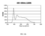
- Example 1 shows the much higher numeral value in the wavelength band of 480 ⁇ 510 nm at a color temperature of 3000K, compared to Comparative Example 1.
- the numeral values of the emission wavelength bands corresponding to specific color indices (R9 ⁇ R15) at the color temperatures of 3500K and 4000K were much higher in Examples 3 and 5 than in Comparative Examples 3 and 5.
- the numeral values of the emission wavelength bands corresponding to specific color indices (R9 ⁇ R15) in the color temperature range from 5000K to 6500K were remarkably higher in Examples 7, 9 and 11 than in Comparative Examples 7, 9 and 11.
- FIG. 12 illustrates the overall results of the emission spectra of FIGS. 6 to 11 , in which (a) shows the emission spectra of the comparative examples and (b) shows the emission spectra of the examples.
- the peak wavelength was formed in the range of 485 ⁇ 504 nm in the emission spectra of the examples according to the present invention, whereas there was no peak wavelength in the range of 485 ⁇ 504 nm in the emission spectra of the comparative examples as shown in FIG. 12( a ) .
- the peak wavelengths in the range of 485 ⁇ 504 nm in the emission spectrum according to the present invention are formed, and thereby R12 may be increased to 90% or more. Furthermore, R9 may be greatly increased by virtue of the formation of the peak wavelengths in the range of 485 ⁇ 504 nm. Consequently, specific color rendering indices R9 to R15 may be uniformly improved.
- the CRI may become uniform in the color temperature range from 3000K to 6500K. Especially, R9 and R12 may be drastically improved.
Landscapes
- Chemical & Material Sciences (AREA)
- Engineering & Computer Science (AREA)
- Materials Engineering (AREA)
- Organic Chemistry (AREA)
- Inorganic Chemistry (AREA)
- Led Device Packages (AREA)
- Non-Portable Lighting Devices Or Systems Thereof (AREA)
- Luminescent Compositions (AREA)
Abstract
Description
(Ba,Eu)Six(O,Cl)xNx (1<x<5) (Chemical Formula 1)
(Sr,Ba,Ca)xSiO2x:Eu (1<x<5) (Chemical Formula 2)
Si6-yAlyOyN8-y:Eu (0.1<y<0.5) (Chemical Formula 3)
Al8-zLuzO12:Ce++ (1<z<5) (Chemical Formula 4)
(Sr,Ca)AlSiNx:Eu (1<x<5) (Chemical Formula 5)
CaAlSiNy:Eu (1<y<5) (Chemical Formula 6)
Claims (3)
Applications Claiming Priority (5)
| Application Number | Priority Date | Filing Date | Title |
|---|---|---|---|
| KR1020130117971A KR101417874B1 (en) | 2013-10-02 | 2013-10-02 | White Light Emitting Device with High Color Rendering Index |
| KR10-2013-0117971 | 2013-10-02 | ||
| KR10-2014-0071997 | 2014-06-13 | ||
| KR1020140071997A KR101706600B1 (en) | 2014-06-13 | 2014-06-13 | White Light Emitting Device with High Color Rendering Index |
| PCT/KR2014/007614 WO2015050317A1 (en) | 2013-10-02 | 2014-08-18 | White light emitting device having high color rendering |
Publications (2)
| Publication Number | Publication Date |
|---|---|
| US20160218255A1 US20160218255A1 (en) | 2016-07-28 |
| US10020428B2 true US10020428B2 (en) | 2018-07-10 |
Family
ID=52778879
Family Applications (1)
| Application Number | Title | Priority Date | Filing Date |
|---|---|---|---|
| US14/917,380 Active US10020428B2 (en) | 2013-10-02 | 2014-08-18 | White light emitting device having high color rendering |
Country Status (5)
| Country | Link |
|---|---|
| US (1) | US10020428B2 (en) |
| EP (2) | EP3557635B1 (en) |
| JP (2) | JP6148395B2 (en) |
| CN (2) | CN108305929B (en) |
| WO (1) | WO2015050317A1 (en) |
Cited By (1)
| Publication number | Priority date | Publication date | Assignee | Title |
|---|---|---|---|---|
| US11133441B2 (en) | 2018-09-28 | 2021-09-28 | Nichia Corporation | Light emitting device and lighting fixture provided with the same |
Families Citing this family (22)
| Publication number | Priority date | Publication date | Assignee | Title |
|---|---|---|---|---|
| US9735323B2 (en) * | 2015-06-30 | 2017-08-15 | Nichia Corporation | Light emitting device having a triple phosphor fluorescent member |
| TWM521008U (en) * | 2016-01-27 | 2016-05-01 | 光寶科技股份有限公司 | Lamp device and its lighting module |
| US10823355B2 (en) * | 2016-01-27 | 2020-11-03 | Lite-On Electronics (Guangzhou) Limited | Light-emitting module for vehicle lamp |
| US10555397B2 (en) | 2016-01-28 | 2020-02-04 | Ecosense Lighting Inc. | Systems and methods for providing tunable warm white light |
| WO2017131699A1 (en) | 2016-01-28 | 2017-08-03 | Ecosense Lighting Inc | Systems for providing tunable white light with high color rendering |
| WO2017133459A1 (en) * | 2016-02-03 | 2017-08-10 | 欧普照明股份有限公司 | Light source module and illumination device |
| CN107830413A (en) * | 2016-09-14 | 2018-03-23 | 深圳市耀铭豪智能科技有限公司 | A kind of full-spectrum LED lighting device and preparation method thereof |
| JP2019016632A (en) | 2017-07-04 | 2019-01-31 | 日亜化学工業株式会社 | Light-emitting device |
| WO2019035831A1 (en) * | 2017-08-16 | 2019-02-21 | Ecosense Lighting Inc. | Multi-channel white light device for providing tunable white light with high color rendering |
| CN107461717A (en) * | 2017-08-24 | 2017-12-12 | 欧普照明股份有限公司 | A kind of light source module group and the lighting device including the light source module group |
| KR102230459B1 (en) * | 2017-09-06 | 2021-03-23 | 지엘비텍 주식회사 | D50, D65 Standard LED Light Emitting Module and Lighting Apparatus with High Color Rendering Index |
| WO2019051780A1 (en) * | 2017-09-15 | 2019-03-21 | 厦门市三安光电科技有限公司 | White light led package structure and white light source system |
| JP6940764B2 (en) | 2017-09-28 | 2021-09-29 | 日亜化学工業株式会社 | Light emitting device |
| CN108091751B (en) * | 2017-12-06 | 2020-02-18 | 佛山市国星光电股份有限公司 | A kind of white light LED device and preparation method thereof, LED lamp |
| CN108172677A (en) * | 2017-12-08 | 2018-06-15 | 佛山市国星光电股份有限公司 | A kind of white light LED device and preparation method thereof, LED flash lamp |
| DE102018101428A1 (en) * | 2018-01-23 | 2019-07-25 | Osram Opto Semiconductors Gmbh | Optoelectronic component |
| CN109411456A (en) * | 2018-10-16 | 2019-03-01 | 江苏稳润光电科技有限公司 | A kind of LED light source for fresh lamp illumination |
| JP7133744B1 (en) * | 2019-08-27 | 2022-09-08 | シグニファイ ホールディング ビー ヴィ | Lighting device for illuminating an aquarium |
| JP7348521B2 (en) * | 2019-12-24 | 2023-09-21 | 日亜化学工業株式会社 | light emitting device |
| US11293602B2 (en) * | 2020-02-28 | 2022-04-05 | Glbtech Co., Ltd. | High color rendering D50/D65 standard LED illuminant module and lighting apparatus |
| CN111933782A (en) * | 2020-07-31 | 2020-11-13 | 佛山市国星光电股份有限公司 | White LED light source and LED lamp comprising same |
| CN113937202B (en) * | 2021-09-29 | 2024-05-14 | 佛山市国星光电股份有限公司 | White light source and white light source system |
Citations (36)
| Publication number | Priority date | Publication date | Assignee | Title |
|---|---|---|---|---|
| WO2001089001A2 (en) | 2000-05-15 | 2001-11-22 | General Electric Company | White light emitting phosphor blends for led devices |
| US20020063301A1 (en) | 2000-09-21 | 2002-05-30 | Tetsuya Hanamoto | Semiconductor light-emitting device and light-emitting display device therewith |
| EP1278250A2 (en) | 2001-07-16 | 2003-01-22 | Patent-Treuhand-Gesellschaft für elektrische Glühlampen mbH | Illumination device with at least one LED as the light source |
| WO2005087896A1 (en) | 2004-03-12 | 2005-09-22 | National Institute For Materials Science | Phosphor, process for producing the same, lighting fixture and image display unit |
| JP2005285800A (en) | 2004-03-26 | 2005-10-13 | Kyocera Corp | Light emitting device |
| EP1630220A2 (en) | 2004-08-27 | 2006-03-01 | Dowa Mining Co., Ltd. | Phosphor mixture and light emitting device using the same |
| JP2006080443A (en) | 2004-09-13 | 2006-03-23 | Fujikura Ltd | Light emitting diode and light emitting diode manufacturing method |
| US20060091790A1 (en) * | 2004-10-28 | 2006-05-04 | Dowa Mining Co., Ltd. | Phosphor mixture and light emitting device |
| JP2006176546A (en) | 2004-12-20 | 2006-07-06 | Dowa Mining Co Ltd | Phosphor and light source using phosphor |
| US20060186377A1 (en) | 2005-02-22 | 2006-08-24 | Sharp Kabushiki Kaisha | Oxynitride phosphor and semiconductor light-emitting device |
| US20060197432A1 (en) * | 2005-03-01 | 2006-09-07 | Dowa Mining Co., Ltd. | Phosphor mixture and light emitting device |
| WO2006118104A1 (en) | 2005-04-26 | 2006-11-09 | Kabushiki Kaisha Toshiba | White led, and backlight and liquid crystal display device using the same |
| JP2007180377A (en) | 2005-12-28 | 2007-07-12 | Sharp Corp | Light emitting device |
| JP2007191680A (en) | 2005-09-01 | 2007-08-02 | Sharp Corp | Light emitting device |
| US20070278935A1 (en) * | 2006-06-02 | 2007-12-06 | Sharp Kabushiki Kaisha | Wavelength conversion member and light-emitting device |
| US20070284563A1 (en) * | 2004-05-13 | 2007-12-13 | Seoul Semiconductor Co., Ltd. | Light emitting device including rgb light emitting diodes and phosphor |
| KR20080063709A (en) | 2007-01-02 | 2008-07-07 | 삼성전기주식회사 | White light emitting device and light source module for LCD backlight using the same |
| US20080272688A1 (en) | 2006-11-14 | 2008-11-06 | Sharp Kabushiki Kaisha | Phosphor and Method of preparing the same as well as semiconductor light-emitting device and image display |
| EP2056366A1 (en) | 2006-08-14 | 2009-05-06 | Fujikura, Ltd. | Light emitting device and illumination device |
| US20100219770A1 (en) * | 2007-05-14 | 2010-09-02 | Lumimicro Corp., Ltd. | White led device capable of adjusting correlated color temperature |
| US20110031874A1 (en) | 2008-01-21 | 2011-02-10 | Nichia Corporation | Light emitting apparatus |
| WO2011033910A1 (en) | 2009-09-17 | 2011-03-24 | 株式会社東芝 | White-light emitting lamp and white-light led lighting device using same |
| WO2011115820A1 (en) | 2010-03-19 | 2011-09-22 | Nitto Denko Corporation | Garnet-based phosphor ceramic sheets for light emitting device |
| JP2011225822A (en) | 2010-02-26 | 2011-11-10 | Mitsubishi Chemicals Corp | Halophosphate phosphor, light-emitting device using the same, and lighting apparatus |
| JP2012109532A (en) | 2010-09-08 | 2012-06-07 | Mitsubishi Chemicals Corp | Light emitting apparatus, lighting apparatus, and lens |
| JP2013021339A (en) | 2004-04-27 | 2013-01-31 | Panasonic Corp | Light-emitting device |
| EP2554631A2 (en) | 2011-08-02 | 2013-02-06 | Everlight Electronics Co., Ltd | Phosphor composition and white light emitting device using the same |
| JP2013033971A (en) | 2005-06-15 | 2013-02-14 | Nichia Chem Ind Ltd | Light-emitting device |
| KR20130027653A (en) | 2011-09-08 | 2013-03-18 | 엘지이노텍 주식회사 | Led white light source module |
| JP2013078336A (en) | 2012-12-26 | 2013-05-02 | Sharp Corp | Light-emitting device for plant cultivation |
| WO2013061943A1 (en) | 2011-10-24 | 2013-05-02 | 株式会社東芝 | White light source and white light source system using white light source |
| KR20130079804A (en) | 2012-01-03 | 2013-07-11 | 삼성전자주식회사 | White light emitting device, display apparatus and illumination apparatus |
| US20130234584A1 (en) * | 2012-03-09 | 2013-09-12 | Kabushiki Kaisha Toshiba | White light emitting device |
| US20140265921A1 (en) * | 2013-03-13 | 2014-09-18 | Cree, Inc. | Solid State Lighting Apparatus and Methods of Forming |
| US20140299904A1 (en) * | 2013-04-03 | 2014-10-09 | Kabushiki Kaisha Toshiba | Light emitting device |
| US20150014725A1 (en) * | 2013-07-12 | 2015-01-15 | Lg Innotek Co., Ltd. | Phosphor and light emitting device having the same |
Family Cites Families (1)
| Publication number | Priority date | Publication date | Assignee | Title |
|---|---|---|---|---|
| US8461613B2 (en) * | 2008-05-27 | 2013-06-11 | Interlight Optotech Corporation | Light emitting device |
-
2014
- 2014-08-18 WO PCT/KR2014/007614 patent/WO2015050317A1/en not_active Ceased
- 2014-08-18 JP JP2016508915A patent/JP6148395B2/en active Active
- 2014-08-18 EP EP19173442.5A patent/EP3557635B1/en active Active
- 2014-08-18 CN CN201810205523.8A patent/CN108305929B/en active Active
- 2014-08-18 CN CN201480066061.6A patent/CN105814699B/en not_active Expired - Fee Related
- 2014-08-18 US US14/917,380 patent/US10020428B2/en active Active
- 2014-08-18 EP EP14850710.6A patent/EP3054490B1/en not_active Not-in-force
-
2016
- 2016-12-13 JP JP2016241369A patent/JP6407243B2/en active Active
Patent Citations (52)
| Publication number | Priority date | Publication date | Assignee | Title |
|---|---|---|---|---|
| US6621211B1 (en) * | 2000-05-15 | 2003-09-16 | General Electric Company | White light emitting phosphor blends for LED devices |
| WO2001089001A2 (en) | 2000-05-15 | 2001-11-22 | General Electric Company | White light emitting phosphor blends for led devices |
| US20020063301A1 (en) | 2000-09-21 | 2002-05-30 | Tetsuya Hanamoto | Semiconductor light-emitting device and light-emitting display device therewith |
| JP2002171000A (en) | 2000-09-21 | 2002-06-14 | Sharp Corp | Semiconductor light emitting device and light emitting display device using the same |
| EP1278250A2 (en) | 2001-07-16 | 2003-01-22 | Patent-Treuhand-Gesellschaft für elektrische Glühlampen mbH | Illumination device with at least one LED as the light source |
| WO2005087896A1 (en) | 2004-03-12 | 2005-09-22 | National Institute For Materials Science | Phosphor, process for producing the same, lighting fixture and image display unit |
| JP2005285800A (en) | 2004-03-26 | 2005-10-13 | Kyocera Corp | Light emitting device |
| JP2013021339A (en) | 2004-04-27 | 2013-01-31 | Panasonic Corp | Light-emitting device |
| US20070284563A1 (en) * | 2004-05-13 | 2007-12-13 | Seoul Semiconductor Co., Ltd. | Light emitting device including rgb light emitting diodes and phosphor |
| EP1630220A2 (en) | 2004-08-27 | 2006-03-01 | Dowa Mining Co., Ltd. | Phosphor mixture and light emitting device using the same |
| US20060045832A1 (en) * | 2004-08-27 | 2006-03-02 | Dowa Mining Co., Ltd. | Phosphor mixture and light emitting device using the same |
| JP2006080443A (en) | 2004-09-13 | 2006-03-23 | Fujikura Ltd | Light emitting diode and light emitting diode manufacturing method |
| US20060091790A1 (en) * | 2004-10-28 | 2006-05-04 | Dowa Mining Co., Ltd. | Phosphor mixture and light emitting device |
| JP2006176546A (en) | 2004-12-20 | 2006-07-06 | Dowa Mining Co Ltd | Phosphor and light source using phosphor |
| US20060186377A1 (en) | 2005-02-22 | 2006-08-24 | Sharp Kabushiki Kaisha | Oxynitride phosphor and semiconductor light-emitting device |
| US20060197432A1 (en) * | 2005-03-01 | 2006-09-07 | Dowa Mining Co., Ltd. | Phosphor mixture and light emitting device |
| WO2006118104A1 (en) | 2005-04-26 | 2006-11-09 | Kabushiki Kaisha Toshiba | White led, and backlight and liquid crystal display device using the same |
| KR20070119750A (en) | 2005-04-26 | 2007-12-20 | 가부시끼가이샤 도시바 | White LEDs, backlights using them, and liquid crystal displays |
| US20090166652A1 (en) * | 2005-04-26 | 2009-07-02 | Kabushiki Kaisha Toshiba | White LED, Backlight Using the Same, and Liquid Crystal Display Device |
| JP2013033971A (en) | 2005-06-15 | 2013-02-14 | Nichia Chem Ind Ltd | Light-emitting device |
| JP2007191680A (en) | 2005-09-01 | 2007-08-02 | Sharp Corp | Light emitting device |
| JP2007180377A (en) | 2005-12-28 | 2007-07-12 | Sharp Corp | Light emitting device |
| US20070278935A1 (en) * | 2006-06-02 | 2007-12-06 | Sharp Kabushiki Kaisha | Wavelength conversion member and light-emitting device |
| US20090146549A1 (en) * | 2006-08-14 | 2009-06-11 | Fujikura Ltd. | Light emitting device and illumination device |
| EP2056366A1 (en) | 2006-08-14 | 2009-05-06 | Fujikura, Ltd. | Light emitting device and illumination device |
| KR20090048589A (en) | 2006-08-14 | 2009-05-14 | 가부시키가이샤후지쿠라 | Light emitting device and lighting device |
| US20080272688A1 (en) | 2006-11-14 | 2008-11-06 | Sharp Kabushiki Kaisha | Phosphor and Method of preparing the same as well as semiconductor light-emitting device and image display |
| KR20080063709A (en) | 2007-01-02 | 2008-07-07 | 삼성전기주식회사 | White light emitting device and light source module for LCD backlight using the same |
| US20080180948A1 (en) | 2007-01-02 | 2008-07-31 | Samsung Electro-Mechanics Co., Ltd. | White light emitting device and light source module for liquid crystal display backlight using the same |
| US20100219770A1 (en) * | 2007-05-14 | 2010-09-02 | Lumimicro Corp., Ltd. | White led device capable of adjusting correlated color temperature |
| US20110031874A1 (en) | 2008-01-21 | 2011-02-10 | Nichia Corporation | Light emitting apparatus |
| KR20120043115A (en) | 2009-09-17 | 2012-05-03 | 도시바 마테리알 가부시키가이샤 | White-light emitting lamp and white-light led lighting device using same |
| US20120187824A1 (en) * | 2009-09-17 | 2012-07-26 | Toshiba Materials Co., Ltd. | White light emitting lamp and white led lighting apparatus including the same |
| WO2011033910A1 (en) | 2009-09-17 | 2011-03-24 | 株式会社東芝 | White-light emitting lamp and white-light led lighting device using same |
| JP2011225822A (en) | 2010-02-26 | 2011-11-10 | Mitsubishi Chemicals Corp | Halophosphate phosphor, light-emitting device using the same, and lighting apparatus |
| US20110227477A1 (en) * | 2010-03-19 | 2011-09-22 | Nitto Denko Corporation | Garnet-based phosphor ceramic sheets for light emitting device |
| WO2011115820A1 (en) | 2010-03-19 | 2011-09-22 | Nitto Denko Corporation | Garnet-based phosphor ceramic sheets for light emitting device |
| JP2013526007A (en) | 2010-03-19 | 2013-06-20 | 日東電工株式会社 | Garnet phosphor ceramic sheet for light emitting devices |
| JP2012109532A (en) | 2010-09-08 | 2012-06-07 | Mitsubishi Chemicals Corp | Light emitting apparatus, lighting apparatus, and lens |
| US20130033167A1 (en) | 2011-08-02 | 2013-02-07 | Everlight Electronics Co., Ltd. | Phosphor Composition And White Light Emitting Device Using The Same |
| KR20130018529A (en) | 2011-08-02 | 2013-02-25 | 에버라이트 일렉트로닉스 컴패니 리미티드 | Phosphor compositon and white light emitting device using the same |
| EP2554631A2 (en) | 2011-08-02 | 2013-02-06 | Everlight Electronics Co., Ltd | Phosphor composition and white light emitting device using the same |
| KR20130027653A (en) | 2011-09-08 | 2013-03-18 | 엘지이노텍 주식회사 | Led white light source module |
| WO2013061943A1 (en) | 2011-10-24 | 2013-05-02 | 株式会社東芝 | White light source and white light source system using white light source |
| KR20130079804A (en) | 2012-01-03 | 2013-07-11 | 삼성전자주식회사 | White light emitting device, display apparatus and illumination apparatus |
| US20130234584A1 (en) * | 2012-03-09 | 2013-09-12 | Kabushiki Kaisha Toshiba | White light emitting device |
| JP2013187485A (en) | 2012-03-09 | 2013-09-19 | Toshiba Corp | White light-emitting device |
| KR20130103360A (en) | 2012-03-09 | 2013-09-23 | 가부시끼가이샤 도시바 | White light emitting device |
| JP2013078336A (en) | 2012-12-26 | 2013-05-02 | Sharp Corp | Light-emitting device for plant cultivation |
| US20140265921A1 (en) * | 2013-03-13 | 2014-09-18 | Cree, Inc. | Solid State Lighting Apparatus and Methods of Forming |
| US20140299904A1 (en) * | 2013-04-03 | 2014-10-09 | Kabushiki Kaisha Toshiba | Light emitting device |
| US20150014725A1 (en) * | 2013-07-12 | 2015-01-15 | Lg Innotek Co., Ltd. | Phosphor and light emitting device having the same |
Non-Patent Citations (40)
| Title |
|---|
| European Patent Abstract (in English) of EP Pub. No. 1278250 A2, Pub. Date Jan. 22, 2003, downloaded on Jul. 27, 2017 from https://worldwide.espacenet.com/. |
| International Search Report (in English) of European Patent App. No. 20130018529 A1 (PCT/JP2007/064861), Pub. Date May 6, 2009, dated Sep. 25, 2007 from Japanese Patent Office. |
| International Search Report (in English) of WIPO Pub. No, WO2013/061943 A1 (Int'l App. No, PCT/JP2012/077296), Pub. Date May 2, 2013. |
| International Search Report (in English) of WIPO Pub. No. WO2006/118104 A1 (Int'l App. No. PCT/JP2006/308636), Pub. Date Nov. 9, 2006. |
| International Search Report (in English) of WIPO Pub. No. WO2011/033910 A1 (Int'l App. No. PCT/JP2010/064382), Pub. Date Mar. 24, 2011. |
| International Search Report (in Japanese) of WIPO Pub. No. WO2006/118104 A1 (Int'l App. No. PCT/JP2006/308636), Pub. Date Nov. 9, 2006. |
| International Search Report (in Japanese) of WIPO Pub. No. WO2011/033910 A1 (Int'l App. No. PCT/JP2010/064382), Pub. Date Mar. 24, 2011. |
| International Search Report (in Japanese) WIPO Pub. No. WO2013/061943 A1 (Int'l App. No. PCT/JP2012/077296), Pub. Date May 2, 2013. |
| International Search Report, Int'l App. No. PCT/US2011/027990, (Int'l Pub. No. WO 2011/115820 A1, Pub. Date Sep. 22, 2011), date of mailing of the International search report: Jul. 21, 2011. |
| Japanese Patent Abstract (in English) of JP Pub. No. 2002171000 A, Pub. Date Jun. 14, 2002, downloaded on Mar. 21, 2017 from https://worldwide.espacenet.com/. |
| Japanese Patent Abstract (in English) of JP Pub. No. 2005-285800 A, Pub. Date Oct. 13, 2005, downloaded on Jul. 27, 2017 from https://www4.j-platpat.inpit.go.jp/eng. |
| Japanese Patent Abstract (in English) of JP Pub. No. 2006-080443 A, Pub. Date Mar. 23, 2006, downloaded on Jul. 27, 2017 from https://www4.j-platpat.inpit.go.jp/eng. |
| Japanese Patent Abstract (in English) of JP Pub. No. 2006-176546 A, Pub. Date Jul. 6, 2006, downloaded on Jul. 27, 2017 from https://www4.j-platpat.inpit.go.jp/eng. |
| Japanese Patent Abstract (in English) of JP Pub. No. 2007-180377 A, Pub. Date Jul. 12, 2007, downloaded on Jul. 27, 2017 from https://www4.j-platpat. inpit.go.jp/eng. |
| Japanese Patent Abstract (in English) of JP Pub. No. 2007-191680 A, Pub. Date Aug. 2, 2007, downloaded on Jun. 29, 2016 from https://www4.j-platpat.inpit.go.jp/. |
| Japanese Patent Abstract (in English) of JP Pub. No. 2011-225822 A, downloaded on Nov. 24, 2016 from https://www.4.j-platpat.inpit,go.jp/eng/. |
| Japanese Patent Abstract (in English) of JP Pub. No. 2012-109532 A, Pub. Date Jun. 7, 2012, downloaded on Sep. 17, 2017 from https://worldwide.espacenet.com/. |
| Japanese Patent Abstract (in English) of JP Pub. No. 2013021339 A, Pub. Date Jan. 31, 2013, downloaded on Mar. 21, 2017 from https://worldwide.espacenet.com/ |
| Japanese Patent Abstract (in English) of JP Pub. No. 2013-033971 A, downloaded on Nov. 24, 2016 from https://www4.j-platpat.inpit.go.jp/eng/. |
| Japanese Patent Abstract (in English) of JP Pub. No. 2013078336 A, Pub. Date May 2, 2013, downloaded on Mar. 21, 2017 from https://worldwide.espacenet.com/. |
| Japanese Patent Abstract (in English) of JP Pub. No. 2013-187485 A, downloaded on Sep. 19, 2013 from https://www4.j-platpat.inpit.go.jp/eng. |
| Kijima, N. et al.; "A New Yellow Phoaphor La3Si6N11:Ce3+ for White LEDs"; ESC Transactions; Jan. 1, 2009, pp. 247-252. |
| Korean Patent Abstract (in English) of KR Pub. No. 1020070119750 A, Pub. Date Dec. 20, 2007, downloaded on Feb. 17, 2016 from http://worldwide.espacenet.com. |
| Korean Patent Abstract (in English) of KR Pub. No. 1020090048589 A, Pub. Date May 14, 2009, downloaded on Jun. 29, 2016 from http://kpa.kipris.or.kr. |
| Korean Patent Abstract (in English) of KR Pub. No. 1020120043115 A, Pub. Date May 3, 2012, downloaded on Feb. 17, 2016 from http://worldwide.espacenet.com. |
| Korean Patent Abstract (in English) of KR Pub. No. 1020130103360 A, Pub. Date Sep. 23, 2013, downloaded on Feb. 17, 2016 from http://worldwide.espacenet.com. |
| Korean Patent Abstract (in English) of KR Pub. No. 20080063709 A, Pub. Date Jul. 7, 2008, downloaded on Mar. 21, 2017 from https://worldwide.espacenet.com/. |
| Korean Patent Abstract (in English) of KR Pub. No. 20130018529 A, Pub. Date Feb. 25, 2013, downloaded on Mar. 21, 2017 from https://worldwide.espacenet.com/. |
| Korean Patent Abstract (in English) of KR Pub. No. 20130027653 A, Pub. Date Mar. 18, 2013, downloaded on Mar. 21, 2017 from https://worldwide.espacenet.com/. |
| Korean Patent Abstract (in English) of KR Pub. No. 20130079804 A, Pub. Date Jul. 11, 2013, downloaded on Mar. 21, 2017 from https://worldwide.espacenet.com/. |
| Office Action dated Feb. 23, 2016, Issued by Korean Intellectual Property Office, in App. No. 10-2014-0071997 (in Korean). |
| Office Action dated May 14, 2015, Issued by Korean Intellectual Property Office, in App. No. 10-2014-0071997 (in Korean). |
| Office Action from China Patent & Trademark Office for App. No. 201430066061.6, dated Aug. 29, 2017. |
| Office Action from Japanese Patent Office for App. No. 2016-241369, dated Aug. 31, 2017. |
| Partial European Search Report (in English) of European Patent App. No. 12177890 (EP2554631A2), Pub. Date Feb. 6, 2013, search completion Jul. 9, 2014 from European Patent Office (EPO). |
| Supplementary Partial European Search Report (in English) of European Patent App. No. 14850710, search completion Jun. 12, 2017 from European Patent Office (EPO). |
| WIPO Patent Abstract (English/Japanese) of WIPO Pub. No. W02006/118104 A1, Pub. Date Nov. 9, 2006. |
| WIPO Patent Abstract (English/Japanese) of WIPO Pub. No. W02011/033910 A1, Pub. Date Mar. 24, 2011. |
| WIPO Patent Abstract (English/Japanese) of WIPO Pub. No. WO2013/061943 A1, Pub. Date May 2, 2013. |
| WIPO Patent Abstract (in English) of WO Pub, No. 2005-087896 A1, Pub. Date Sep. 22, 2005, downloaded on Jul. 27, 2017 from https://patentscope.wipo.int/search/en/. |
Cited By (1)
| Publication number | Priority date | Publication date | Assignee | Title |
|---|---|---|---|---|
| US11133441B2 (en) | 2018-09-28 | 2021-09-28 | Nichia Corporation | Light emitting device and lighting fixture provided with the same |
Also Published As
| Publication number | Publication date |
|---|---|
| CN105814699B (en) | 2019-12-31 |
| JP6407243B2 (en) | 2018-10-17 |
| JP6148395B2 (en) | 2017-06-14 |
| CN108305929B (en) | 2021-02-05 |
| JP2017059854A (en) | 2017-03-23 |
| EP3054490B1 (en) | 2019-06-26 |
| WO2015050317A1 (en) | 2015-04-09 |
| EP3557635A1 (en) | 2019-10-23 |
| US20160218255A1 (en) | 2016-07-28 |
| JP2016515770A (en) | 2016-05-30 |
| EP3054490A4 (en) | 2017-07-19 |
| CN105814699A (en) | 2016-07-27 |
| CN108305929A (en) | 2018-07-20 |
| EP3557635B1 (en) | 2020-05-27 |
| EP3054490A1 (en) | 2016-08-10 |
Similar Documents
| Publication | Publication Date | Title |
|---|---|---|
| US10020428B2 (en) | White light emitting device having high color rendering | |
| US10568172B2 (en) | Dimmable solid-state light emitting devices | |
| JP5599483B2 (en) | Light emitting device using non-stoichiometric tetragonal alkaline earth silicate phosphor | |
| JP6275829B2 (en) | Light emitting device | |
| KR101417874B1 (en) | White Light Emitting Device with High Color Rendering Index | |
| KR20060101295A (en) | Light emitting elements and lighting fixtures | |
| JP2009055043A (en) | Light emitting device using non-stoichiometric tetragonal alkaline earth silicate phosphor | |
| CN101072844A (en) | Illumination system comprising a radiation source and a luminescent material | |
| US12595409B2 (en) | High luminous efficacy phosphor converted white LEDs | |
| JP2008285606A (en) | Phosphor, method for manufacturing the same, and light emitting device | |
| CN103797087A (en) | Luminescent substance mixture, optoelectronic component having a luminescent substance mixture, and street lamps having a luminescent substance mixture | |
| US10236425B2 (en) | White light emitting device having high color rendering | |
| CN102142503A (en) | White light generation method and white light emitting diode device | |
| CN105793391A (en) | Luminescent-substance mixture, light-emitting semiconductor component having luminescent-substance mixture, and streetlamp having luminescent-substance mixture | |
| KR101706600B1 (en) | White Light Emitting Device with High Color Rendering Index | |
| KR101093575B1 (en) | Red nitride phosphor and white light emitting diode using same | |
| KR102130817B1 (en) | White Light Emitting Device with High Color Rendering Index | |
| KR101652258B1 (en) | White Light Emitting Device with High Color Rendering Index | |
| KR101855391B1 (en) | White Light Emitting Device with High Color Rendering Index | |
| KR102496975B1 (en) | Phosphor compositions and lighting apparatus thereof | |
| KR101409489B1 (en) | Silicon oxynitride phosphor and light device having the same | |
| JP4948015B2 (en) | Aluminate blue phosphor and light emitting device using the same | |
| KR100966296B1 (en) | Nitride red phosphors and white light emitting diode using rare-earth-co-doped nitride red phosphors | |
| KR102092676B1 (en) | Light emitting device |
Legal Events
| Date | Code | Title | Description |
|---|---|---|---|
| AS | Assignment |
Owner name: GLBTECH CO., LTD., KOREA, REPUBLIC OF Free format text: ASSIGNMENT OF ASSIGNORS INTEREST;ASSIGNOR:KIM, HAN DO;REEL/FRAME:037920/0910 Effective date: 20160229 |
|
| STCF | Information on status: patent grant |
Free format text: PATENTED CASE |
|
| MAFP | Maintenance fee payment |
Free format text: PAYMENT OF MAINTENANCE FEE, 4TH YR, SMALL ENTITY (ORIGINAL EVENT CODE: M2551); ENTITY STATUS OF PATENT OWNER: SMALL ENTITY Year of fee payment: 4 |
|
| FEPP | Fee payment procedure |
Free format text: MAINTENANCE FEE REMINDER MAILED (ORIGINAL EVENT CODE: REM.); ENTITY STATUS OF PATENT OWNER: SMALL ENTITY |