US10015930B2 - Positioning and safety apparatus suitable for control of concave suspension in a combine harvester - Google Patents
Positioning and safety apparatus suitable for control of concave suspension in a combine harvester Download PDFInfo
- Publication number
- US10015930B2 US10015930B2 US15/374,711 US201615374711A US10015930B2 US 10015930 B2 US10015930 B2 US 10015930B2 US 201615374711 A US201615374711 A US 201615374711A US 10015930 B2 US10015930 B2 US 10015930B2
- Authority
- US
- United States
- Prior art keywords
- spring
- force transmission
- force
- control
- movable
- Prior art date
- Legal status (The legal status is an assumption and is not a legal conclusion. Google has not performed a legal analysis and makes no representation as to the accuracy of the status listed.)
- Active, expires
Links
Images


Classifications
-
- A—HUMAN NECESSITIES
- A01—AGRICULTURE; FORESTRY; ANIMAL HUSBANDRY; HUNTING; TRAPPING; FISHING
- A01F—PROCESSING OF HARVESTED PRODUCE; HAY OR STRAW PRESSES; DEVICES FOR STORING AGRICULTURAL OR HORTICULTURAL PRODUCE
- A01F12/00—Parts or details of threshing apparatus
- A01F12/18—Threshing devices
- A01F12/28—Devices for adjusting the concaves
-
- A—HUMAN NECESSITIES
- A01—AGRICULTURE; FORESTRY; ANIMAL HUSBANDRY; HUNTING; TRAPPING; FISHING
- A01D—HARVESTING; MOWING
- A01D41/00—Combines, i.e. harvesters or mowers combined with threshing devices
- A01D41/12—Details of combines
-
- A—HUMAN NECESSITIES
- A01—AGRICULTURE; FORESTRY; ANIMAL HUSBANDRY; HUNTING; TRAPPING; FISHING
- A01D—HARVESTING; MOWING
- A01D75/00—Accessories for harvesters or mowers
- A01D75/18—Safety devices for parts of the machines
- A01D75/182—Avoiding overload
-
- A—HUMAN NECESSITIES
- A01—AGRICULTURE; FORESTRY; ANIMAL HUSBANDRY; HUNTING; TRAPPING; FISHING
- A01F—PROCESSING OF HARVESTED PRODUCE; HAY OR STRAW PRESSES; DEVICES FOR STORING AGRICULTURAL OR HORTICULTURAL PRODUCE
- A01F7/00—Threshing apparatus
- A01F7/02—Threshing apparatus with rotating tools
Definitions
- the present invention is related to a positioning and safety apparatus that is primarily, but not exclusively, suitable for use in the suspension of concaves in a combine harvester.
- Agricultural combine harvesters comprise threshing rotors that rotate with respect to concave gratings, in short ‘concaves’, in order to separate grains from residue crop materials such as stalks and leaves. Threshing rotors are arranged transversally or longitudinally with respect to the driving direction of the harvester. The distance between the concaves and the rotors is adjustable in order to be able to adapt the combine to different crop types and harvesting conditions.
- a safety mechanism is required to protect the combine when dense swathes of crops or large rigid objects enter the machine, such as stones or pieces of metal or wood.
- a shear-bolt system is installed. When a large object enters the space between a rotor and a concave, the instantaneous force breaks the bolt, and the concave falls away from the rotor, so as to prevent damage.
- the present invention is related to an apparatus that ensures the control of the position of a component of a mechanical system, such as an adjustable concave in a combine harvester, while at the same time exhibiting a safety function that is reversible without requiring a long downtime of the system.
- the apparatus comprises a control part and an auxiliary part, both pivotable about the same axis, and means to maintain these two parts in an assembled state by a spring force, as long as the component is subjected to forces below a given limit.
- the auxiliary part and the control part are configured to become separated in such a manner that they can be reassembled by the intervention of an actuator included in the apparatus of the invention and—during normal operation—used for controlling the position of the component.
- the apparatus is designed so that its safety function resembles the operation of a shear bolt.
- the invention is in particular related to a positioning and safety apparatus as disclosed in the appended claims.
- FIG. 1 is a schematic side view of an axial flow combine harvester, showing the position of the threshing rotors and concaves.
- FIG. 2 illustrates the general concept as known in the art, of a system for adjusting the position of the concaves with respect to the threshing rotors, in the axial flow combine of FIG. 1 .
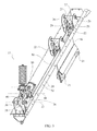
- FIGS. 3 and 4 illustrate a 3D view and a side view of a system for adjusting the position of the concaves, provided with an apparatus according to an embodiment of the invention.
- FIG. 5 shows a detailed view of the apparatus according to the embodiment shown in FIGS. 3 and 4 .
- FIGS. 6 a and 6 b show the control part applicable in an embodiment of the apparatus of the invention, wherein the control part is a plate of a suitable shape and having suitable dimensions, which make the apparatus operable in a similar manner to a shear-bolt.
- FIGS. 7 a to 7 f show a step-by-step evolution of the position of the apparatus during a breakage, as a function of the angle between the control part and the auxiliary part of the apparatus.
- FIG. 8 is a curve showing the relation of the force required to move the roller, as a function of the angles shown in FIGS. 7 a to 7 f.
- FIGS. 9 a to 9 f illustrate the manner in which the apparatus is brought back to its initial state after a breakage has occurred.
- FIG. 10 illustrates an alternative embodiment of an apparatus according to the invention.
- FIG. 1 shows the main components of an axial flow combine harvester, mounted on front and rear wheels 1 and 2 .
- Crops are cut from the field by the header assembly 3 , and supplied by the feeder 4 to a twin set of threshing rotors 5 , arranged along the longitudinal direction of the harvester and tilted slightly upward with respect to the horizontal.
- the threshing rotors 5 are rotatably mounted with respect to concaves.
- Preferably several sets 6 a - 6 c of concaves are mounted along the length of the rotors, with at least the first set 6 a being adjustable with respect to the rotors.
- the driver's cabin 7 is indicated, as well as the cleaning arrangement, comprising a grain pan 8 , a set of sieves 9 and a blower 10 for blowing light residue material towards the back of the harvester. Grains fall through the sieves and are transported by an assembly of augers and a grain elevator (not shown) to a grain tank 11 .
- FIG. 2 shows a preferred embodiment of this arrangement, provided with a positioning and safety apparatus 17 according to the present invention.
- An elongate gutter-shaped structure 20 is mounted on the chassis of the harvester, above the threshing rotors and the concaves.
- the gutter-shaped structure is an embodiment of the ‘fixed structure’ referred to in the appended claims.
- the rotors and concaves as such are not shown in FIG. 3 .
- the inner edges of the pair of concaves are suspended from the structure 20 via the support plate 16 already described with reference to FIG. 2 .
- the support plate 16 is provided with recesses 21 wherein the edges of the concaves are slidably mounted.
- the plate 16 is itself suspended in two attachment points 22 , from a pair of pivoting structures, each of the latter being provided with a rotatable axle 25 mounted between two fixed brackets 26 .
- the axle 25 comprises a first radially oriented arm 27 connected to an attachment point 22 of the plate 16 via pivotable links 28 .
- the second radial arm 29 is pivotably connected to a control rod 30 extending along the length of the gutter-shaped structure 20 , and connected at its outer end to the positioning and safety apparatus 17 .
- the above-described suspension mechanism of the plate 16 is known as such and described here only for the sake of clarifying the interaction with the apparatus of the invention.
- FIG. 4 shows a side view of the complete mechanism.
- the end 31 of the control rod 30 is pivotably connected to a control plate 35 that is itself pivotably mounted between two fixed support brackets 36 (‘fixed’ meaning immovably attached to the gutter-shaped structure 20 ).
- Rotation of the control plate 35 about its pivot axis 37 actuates a swing movement of the control rod 30 which in turns actuates a rotation of the axles 25 , via the radial arms 29 connected to the rod 30 , which finally results in the lifting or lowering of the support plate 16 , and the adjustment of the position of the concaves. How the control plate's rotation itself is actuated will now be explained, with reference to the more detailed view of the apparatus 17 shown in FIG. 5 , with reference also to FIGS. 3 and 4 for a number of the numerical references used hereafter.
- a fork-shaped component 40 hereafter referred to as the ‘fork’ 40 , is pivotable about the same pivot axis 37 as the control plate 35 , the legs of the fork extending on either side of the control plate 35 , the top of the fork 40 forming a platform 41 on which a mechanical spring 42 is mounted.
- the spring is pre-compressed between a lower end plate 58 and an upper end plate 59 .
- the fork 40 is an embodiment of the ‘auxiliary part’ cited in the summary and in the appended claims. The fork 40 and the control plate 35 are held together by the spring force in the following manner.
- a spring force transmission part 43 is mounted between the legs of the fork 40 and is pivotable with respect to the fork 40 about a pivot axis 44 parallel to the pivot axis 37 of the control plate 35 .
- One end of the force transmission part 43 is pivotably connected to a rod 38 , which runs through an opening in the fork's platform 41 and through the mechanical spring 42 and its lower and upper end plates 58 / 59 .
- the rod is connectable to the upper end plate 59 in the following manner: a screw 39 engages with the threaded end of the rod 38 and allows the positioning of the upper end plate 59 at a given position with respect to the rod 38 , thereby setting a pre-defined pre-stressed condition of the spring 42 .
- the spring force is thus exerted between the force transmission part 43 and the fork 40 . More precisely, the spring ‘pulls’ the rod 38 and thereby the second end of the force transmission part 43 (opposite the end carrying the roller 45 ) towards the platform 41 of the fork 40 . A limited movement of the spring with respect to the platform 41 is made possible by a ball-shaped connection piece 48 between the lower end plate 58 of the spring and the platform 41 .
- the other end of the force transmission part 43 opposite to the first end, as seen with respect its rotation axis 44 , carries a roller 45 that is rotatable with respect to the transmission part 43 about rotation axis 46 .
- the roller 45 is lodged in a seat portion 47 at the top of the control plate 35 , i.e.
- the force transmission part 43 acts as a lever that pushes the roller 45 against the seat portion 47 with a force determined by the spring's pre-compression and the dimensions of the force transmission part 43 .
- the control plate 35 , the fork 40 , the force transmission part 43 and the spring 42 form a single structure that is movable in one way only: by rotation of the control plate 35 about its pivot axis 37 .
- This rotation of the control plate and thus of the complete structure can be set in motion by an actuator 50 that is itself pivotably mounted between fixed brackets 51 , the actuator being pivotable about pivot axis 52 .
- the actuator comprises an electric motor 53 which drives the rotation of a threaded rod 54 .
- the rod 54 is engaged in a threaded opening of a cylinder 55 , the opening being transversal to the cylinder's axis, the cylinder 55 itself being pivotably mounted between the legs of the fork 40 .
- Rotation of the threaded rod 54 therefore displaces the cylinder 55 with respect to the rod 54 , resulting in a rotation of the fork 40 and thereby of the control plate 35 tied to the fork 40 by the spring force.
- This actuated rotation of the control plate 35 results in the actuation of the control rod 30 and of the support plate 16 .
- the rotation of the control plate 35 is made possible furthermore by the fact that the actuator 50 itself is pivotable as a whole about pivot axis 52 . This is the way in which the positioning and safety apparatus 17 controls the position of the concaves during normal operation of the harvester.
- the force exerted on it must be sufficient to counteract the spring force that works to push the roller 45 into this seat portion 47 .
- the downward force on the concaves is insufficient to generate this roller release force (i.e. when the obstructions are not large enough to push the concaves downwards)
- the assembly is maintained and the roller 45 stays locked in the seat portion 47 .
- the obstruction entering the space between the concaves and the threshing rotors must be large and rigid enough to push the concaves downwards.
- the apparatus is configured so that as soon as this happens, i.e.
- this release of the roller 45 from its seat portion 47 happens in a very short timespan, in such a manner that the mechanism approximates the operation of a shear-bolt.
- This effect is obtained by a number of measures explained on the basis of a detail of the control plate 35 shown in FIG. 6 a and of the control plate 35 and roller assembly in the locked state in FIG. 6 b .
- the dimensions shown are examples and not limiting to the claim scope. Application of these dimensions and shapes however ensures the shear-bolt-like operation.
- the seat portion 47 is shaped as a semi-circle with a convex portion 60 to one side, so the roller 45 needs to roll over said convex portion 60 in order to be fully released from the seat portion.
- the distance A between the control plate's pivot axis 37 and the roller's rotation axis 46 needs to be larger than the distance B between the control plate's pivot axis 37 and the transition point 62 between the semi-circular seat portion 47 and the convex portion 60 . If the latter condition is not fulfilled, the force F would act to push the roller 45 more strongly into the seat portion 47 rather than lifting it out of the seat portion. Preferably there is a small clearance 66 between the roller 45 and the seat portion 47 when the apparatus is in the locked condition, so as not to obstruct the movement of the roller, once this movement has initiated.
- FIG. 8 shows the normalized force required to move the roller 45 , as a function of the angle between the control plate 35 and the fork 40 , as shown in the sequence of drawings 7 a to 7 f . It is seen that this force drops sharply as a function of the angle.
- the apparatus of the invention allows the roller 45 to be brought back to its position lodged in the seat portion 47 , by using the actuator 50 .
- the concaves fall down to their lowest position, defined by a stop surface mounted underneath the support plate 16 .
- the roller has come to a halt on the slanted portion 65 at the top of the control plate 35 , as shown in FIG. 9 a .
- Actuating the actuator 50 now has the following effect: if the threaded rod 54 is rotated so that the cylinder 55 is pushed away from the actuator 50 , this will result in the rotation of the fork 40 about its rotation axis 37 , and relative to the control plate 35 , given that the fork 40 is now no longer tied to the control plate 35 . This rotation will gradually push the roller 45 upwards along the slanted portion 65 of the control plate, over the convex portion 60 , until the roller snaps back into the seat portion 47 as illustrated in FIGS. 9 a to 9 c .
- the apparatus of the invention thereby makes it possible to quickly reset the concaves after a breakage, without requiring emptying of the grain tank, and thus allowing to resume operation without excessive downtime.
- the mechanical spring 42 may be replaced by a pneumatic or hydraulic spring.
- the actuator 50 may be any suitable type of actuator capable of controlling the above-described movements.
- the fork 40 may be replaced by any other suitably shaped part.
- the spring force may be arranged to act directly on the end of the force transmission part 43 that carries the roller, instead of on the opposite end as is the case in the drawings described so far. This variant is illustrated in FIG. 10 .
- the same numerical references used above are used again in this figure to indicate the same parts or parts having the same function.
- the fork 40 is now mounted to one side of the control plate 35 .
- a threaded rod 70 is pivotably connected to an extension 71 of the fork.
- the rod 70 runs through the force transmission part 43 and the lower and upper end plates 58 / 59 of the mechanical spring 42 , with the spring being maintained in a compressed state in the same manner as in the embodiment of FIG. 5 , i.e. by a bolt 72 engaging with the threaded end of the rod 70 .
- the rod 70 is pulling one end of the fork (defined by extension 71 ) towards the force transmission part 43 , thereby pushing the roller 45 into the seat portion 47 of the control plate 35 .
- the roller 45 can only be released from the seat portion 47 by a force that is capable of counteracting the spring force.
- the actuator 50 brings the apparatus back to its original state, in the manner described above.
- roller 45 As described is the preferred embodiment.
- the roller 45 and seat portion 47 are preferably produced in hardened material, capable of withstanding the high forces. However in situations where the occurring forces are lower, alternatives can be used.
- any other suitable connection element could be provided, such as an element that glides over the control plate instead of rolling.
- the force transmission part 43 could be an integral part of the auxiliary part 40 , or connected thereto in another way than the way shown in the drawings.
- the apparatus of the invention may be used to control the position and provide a safety release function for other components besides the concaves in a combine harvester.
- the apparatus could, e.g., be used with the counter knives assembly in a chopper arrangement.
- the safety function needs to allow breakage in two opposite directions.
- the control plate 35 may be designed symmetrically with respect to the seat portion 47 , i.e. comprising a convex portion 60 and slanted portion 65 on both sides of the seat portion 47 .
Landscapes
- Life Sciences & Earth Sciences (AREA)
- Environmental Sciences (AREA)
- Harvester Elements (AREA)
Abstract
Description
Claims (14)
Applications Claiming Priority (2)
| Application Number | Priority Date | Filing Date | Title |
|---|---|---|---|
| BE2015/5813 | 2015-12-10 | ||
| BE2015/5813A BE1023185B1 (en) | 2015-12-10 | 2015-12-10 | POSITIONING AND SAFETY DEVICE SUITABLE FOR CONTROLLING THE DORSKORF SUSPENSION IN A CUTTER |
Publications (2)
| Publication Number | Publication Date |
|---|---|
| US20170164560A1 US20170164560A1 (en) | 2017-06-15 |
| US10015930B2 true US10015930B2 (en) | 2018-07-10 |
Family
ID=55272187
Family Applications (1)
| Application Number | Title | Priority Date | Filing Date |
|---|---|---|---|
| US15/374,711 Active 2037-01-10 US10015930B2 (en) | 2015-12-10 | 2016-12-09 | Positioning and safety apparatus suitable for control of concave suspension in a combine harvester |
Country Status (4)
| Country | Link |
|---|---|
| US (1) | US10015930B2 (en) |
| EP (1) | EP3178309B1 (en) |
| BE (1) | BE1023185B1 (en) |
| BR (1) | BR102016028460B1 (en) |
Cited By (1)
| Publication number | Priority date | Publication date | Assignee | Title |
|---|---|---|---|---|
| US10932414B2 (en) * | 2017-11-29 | 2021-03-02 | Agco Corporation | Concave adjustment system in a combine harvester twin axial-flow crop processor |
Families Citing this family (8)
| Publication number | Priority date | Publication date | Assignee | Title |
|---|---|---|---|---|
| BE1025193B1 (en) * | 2017-05-04 | 2018-12-06 | Cnh Industrial Belgium Nv | SELF-LOCKING SECURITY SYSTEM FOR A CHAFFER OF A HARVESTER FOR AGRICULTURAL APPLICATIONS |
| GB201715633D0 (en) * | 2017-09-27 | 2017-11-08 | Agco Int Gmbh | Concave adjustment system in a combine harvester twin axial-flow crop processor |
| US10653068B2 (en) * | 2018-02-21 | 2020-05-19 | Cnh Industrial America Llc | Adjustment and suspension device for concaves |
| CN112705001B (en) * | 2020-12-31 | 2022-06-14 | 高国杰 | Peanut picker raise dust processing apparatus |
| EP4573882A3 (en) | 2022-04-08 | 2025-07-16 | AGCO International GmbH | An adjustment and release unit for a concave of a threshing system of a combine harvester |
| GB202205170D0 (en) | 2022-04-08 | 2022-05-25 | Agco Int Gmbh | Support system for for a concave of a threshing system of a combine harvester |
| GB202217576D0 (en) | 2022-11-24 | 2023-01-11 | Agco Int Gmbh | An adjustable and release unit for a concave of a threshing system of a combine harvester |
| EP4442104A1 (en) | 2023-04-03 | 2024-10-09 | CNH Industrial Belgium N.V. | Positioning apparatus for a rotary combine harvester |
Citations (20)
| Publication number | Priority date | Publication date | Assignee | Title |
|---|---|---|---|---|
| US2616433A (en) * | 1949-07-08 | 1952-11-04 | Deere & Co | Concave-adjusting means for threshers |
| US2794438A (en) * | 1954-06-10 | 1957-06-04 | Case Co J I | Adjustable concave having shear pin |
| US2931363A (en) * | 1957-05-28 | 1960-04-05 | Case Co J I | Concave overload release mechanism |
| DE1950879U (en) | 1966-04-29 | 1966-12-01 | Josef Bautz G M B H | DEVICE FOR ADJUSTING THE GAP WIDTH BETWEEN THRESHING DRUM AND THRESHING BASKET IN COMBINE. |
| US3771530A (en) * | 1972-06-19 | 1973-11-13 | Deere & Co | Combine stone strap |
| US4271850A (en) * | 1980-03-27 | 1981-06-09 | Allis-Chalmers Corporation | Concave safety door with sealing and latching features |
| GB2065437A (en) | 1979-12-17 | 1981-07-01 | Deere & Co | Axial flow threshing device |
| US4484588A (en) * | 1984-03-26 | 1984-11-27 | Allis-Chalmers Corp. | Combined concave and rock door structure |
| US4802496A (en) | 1987-05-19 | 1989-02-07 | Deere & Company | Agricultural concave adjustment means |
| EP0468160A1 (en) * | 1990-07-26 | 1992-01-29 | Claas Ohg | Self-propelled combine |
| US5489239A (en) * | 1994-09-15 | 1996-02-06 | Case Corporation | Rotary combine |
| US20050176484A1 (en) * | 2004-01-12 | 2005-08-11 | Schenk Charles R. | Mechanism and method for automatically transversely positioning the pinch-point of a concave |
| US7392123B2 (en) | 2004-11-01 | 2008-06-24 | Cnh America Llc | System and method to detect a failed shear bolt supporting a concave of an agricultural combine |
| US7393274B2 (en) | 2006-02-01 | 2008-07-01 | Agco Corporation | Combine harvester processing system having adjustable members |
| US7803040B1 (en) | 2009-04-17 | 2010-09-28 | Cnh America Llc | Concave adjust assembly including a torsion axle for damping crop threshing impulse loads |
| EP2377387A2 (en) | 2010-04-17 | 2011-10-19 | CNH Belgium N.V. | Concave adjust assembly including a torsion axle for damping crop threshing impulse loads |
| US8133101B2 (en) | 2009-12-18 | 2012-03-13 | Agco Corporation | Concave adjustment mechanism |
| US8157629B2 (en) | 2008-03-14 | 2012-04-17 | Deere & Company | Concave suspension for a threshing section in a harvesting machine |
| WO2013082236A1 (en) * | 2011-11-29 | 2013-06-06 | Agco Corporation | Constant pressure concave assembly in a combine harvester processing system |
| WO2014191804A1 (en) | 2013-05-31 | 2014-12-04 | Agco Corporation | Combine having cam-operated concave adjustment |
-
2015
- 2015-12-10 BE BE2015/5813A patent/BE1023185B1/en not_active IP Right Cessation
-
2016
- 2016-12-03 BR BR102016028460-0A patent/BR102016028460B1/en active IP Right Grant
- 2016-12-09 EP EP16203085.2A patent/EP3178309B1/en active Active
- 2016-12-09 US US15/374,711 patent/US10015930B2/en active Active
Patent Citations (22)
| Publication number | Priority date | Publication date | Assignee | Title |
|---|---|---|---|---|
| US2616433A (en) * | 1949-07-08 | 1952-11-04 | Deere & Co | Concave-adjusting means for threshers |
| US2794438A (en) * | 1954-06-10 | 1957-06-04 | Case Co J I | Adjustable concave having shear pin |
| US2931363A (en) * | 1957-05-28 | 1960-04-05 | Case Co J I | Concave overload release mechanism |
| DE1950879U (en) | 1966-04-29 | 1966-12-01 | Josef Bautz G M B H | DEVICE FOR ADJUSTING THE GAP WIDTH BETWEEN THRESHING DRUM AND THRESHING BASKET IN COMBINE. |
| US3771530A (en) * | 1972-06-19 | 1973-11-13 | Deere & Co | Combine stone strap |
| GB2065437A (en) | 1979-12-17 | 1981-07-01 | Deere & Co | Axial flow threshing device |
| US4330000A (en) | 1979-12-17 | 1982-05-18 | Deere & Company | Grate adjusting arrangement for an axial flow rotary thresher |
| US4271850A (en) * | 1980-03-27 | 1981-06-09 | Allis-Chalmers Corporation | Concave safety door with sealing and latching features |
| US4484588A (en) * | 1984-03-26 | 1984-11-27 | Allis-Chalmers Corp. | Combined concave and rock door structure |
| US4802496A (en) | 1987-05-19 | 1989-02-07 | Deere & Company | Agricultural concave adjustment means |
| EP0468160A1 (en) * | 1990-07-26 | 1992-01-29 | Claas Ohg | Self-propelled combine |
| US5489239A (en) * | 1994-09-15 | 1996-02-06 | Case Corporation | Rotary combine |
| US20050176484A1 (en) * | 2004-01-12 | 2005-08-11 | Schenk Charles R. | Mechanism and method for automatically transversely positioning the pinch-point of a concave |
| US7118475B2 (en) | 2004-01-12 | 2006-10-10 | Chn America Llc | Mechanism and method for automatically transversely positioning the pinch-point of a concave |
| US7392123B2 (en) | 2004-11-01 | 2008-06-24 | Cnh America Llc | System and method to detect a failed shear bolt supporting a concave of an agricultural combine |
| US7393274B2 (en) | 2006-02-01 | 2008-07-01 | Agco Corporation | Combine harvester processing system having adjustable members |
| US8157629B2 (en) | 2008-03-14 | 2012-04-17 | Deere & Company | Concave suspension for a threshing section in a harvesting machine |
| US7803040B1 (en) | 2009-04-17 | 2010-09-28 | Cnh America Llc | Concave adjust assembly including a torsion axle for damping crop threshing impulse loads |
| US8133101B2 (en) | 2009-12-18 | 2012-03-13 | Agco Corporation | Concave adjustment mechanism |
| EP2377387A2 (en) | 2010-04-17 | 2011-10-19 | CNH Belgium N.V. | Concave adjust assembly including a torsion axle for damping crop threshing impulse loads |
| WO2013082236A1 (en) * | 2011-11-29 | 2013-06-06 | Agco Corporation | Constant pressure concave assembly in a combine harvester processing system |
| WO2014191804A1 (en) | 2013-05-31 | 2014-12-04 | Agco Corporation | Combine having cam-operated concave adjustment |
Non-Patent Citations (1)
| Title |
|---|
| EP16203085, European Search Report, dated Apr. 20, 2017, 5 pages. |
Cited By (1)
| Publication number | Priority date | Publication date | Assignee | Title |
|---|---|---|---|---|
| US10932414B2 (en) * | 2017-11-29 | 2021-03-02 | Agco Corporation | Concave adjustment system in a combine harvester twin axial-flow crop processor |
Also Published As
| Publication number | Publication date |
|---|---|
| EP3178309B1 (en) | 2018-08-22 |
| US20170164560A1 (en) | 2017-06-15 |
| BR102016028460B1 (en) | 2021-09-28 |
| BR102016028460A2 (en) | 2017-06-13 |
| EP3178309A1 (en) | 2017-06-14 |
| BE1023185B1 (en) | 2016-12-13 |
Similar Documents
| Publication | Publication Date | Title |
|---|---|---|
| US10015930B2 (en) | Positioning and safety apparatus suitable for control of concave suspension in a combine harvester | |
| EP3420797B1 (en) | Multi-section composite cutting device with anti-kink element and method for adjusting the height of a cutting device | |
| EP2845462A1 (en) | Articulated harvesting head ground force control circuit | |
| US8910724B2 (en) | Telescoping coulter system and method | |
| EP0958730A1 (en) | Device for actioning and adjusting working cylinders | |
| EP2529614B1 (en) | Mower combination | |
| EP3744168B1 (en) | Crop conditioner hood with integrated swathboard | |
| EP1927277A1 (en) | Agricultural harvester with a transfer device | |
| DE102014106696A1 (en) | Forage | |
| DE102020204860A1 (en) | WEATHER STATION BRACKET FOR HARVESTING MACHINE AND PROCEDURE FOR EXTENDING THE BRACKET | |
| JP5749715B2 (en) | Mower-conditioner with device for evenly spreading grass released backwards towards the ground | |
| DE19847891A1 (en) | Control for front attachment | |
| EP2926643B1 (en) | Agricultural machine | |
| EP4030886B1 (en) | Cutting mechanism with cutting elements which are mounted in a height-elastic manner | |
| US10568264B2 (en) | Harvester with header lift assembly | |
| EP3794932B1 (en) | Pivoting device for uniformly distributing a product on a conveying and cleaning element | |
| US20190090424A1 (en) | Swath Roller Attachment for a Swather Tractor | |
| US7343726B2 (en) | Harvesting machine with a discharge assembly | |
| US9538705B1 (en) | Cutter and a base cut assembly | |
| DE2345022C3 (en) | Floor scanning device for automatic cutting table height adjustment on combine harvesters | |
| EP2829172B1 (en) | Harvester | |
| DE102018215263A1 (en) | Self-propelled harvester with an overloading device | |
| US96576A (en) | Horse hay-rake | |
| EP4674252A1 (en) | Support wheel assembly for a header of a self-propelled harvester | |
| EP4709141A1 (en) | Pick-up attachment for a harvesting machine |
Legal Events
| Date | Code | Title | Description |
|---|---|---|---|
| AS | Assignment |
Owner name: CNH INDUSTRIAL BELGIUM NV, BELGIUM Free format text: ASSIGNMENT OF ASSIGNORS INTEREST;ASSIGNOR:VAN HULLEBUSCH, BART G.L.;REEL/FRAME:045749/0483 Effective date: 20151210 |
|
| AS | Assignment |
Owner name: CNH INDUSTRIAL AMERICA LLC, PENNSYLVANIA Free format text: ASSIGNMENT OF ASSIGNORS INTEREST;ASSIGNOR:CNH INDUSTRIAL BELGIUM NV;REEL/FRAME:046053/0302 Effective date: 20161205 |
|
| STCF | Information on status: patent grant |
Free format text: PATENTED CASE |
|
| AS | Assignment |
Owner name: BLUE LEAF I.P., INC., DELAWARE Free format text: ASSIGNMENT OF ASSIGNORS INTEREST;ASSIGNOR:CNH INDUSTRIAL AMERICA LLC;REEL/FRAME:047494/0078 Effective date: 20181011 |
|
| MAFP | Maintenance fee payment |
Free format text: PAYMENT OF MAINTENANCE FEE, 4TH YEAR, LARGE ENTITY (ORIGINAL EVENT CODE: M1551); ENTITY STATUS OF PATENT OWNER: LARGE ENTITY Year of fee payment: 4 |
|
| MAFP | Maintenance fee payment |
Free format text: PAYMENT OF MAINTENANCE FEE, 8TH YEAR, LARGE ENTITY (ORIGINAL EVENT CODE: M1552); ENTITY STATUS OF PATENT OWNER: LARGE ENTITY Year of fee payment: 8 |