US10011998B1 - Modular patio assembly - Google Patents
Modular patio assembly Download PDFInfo
- Publication number
- US10011998B1 US10011998B1 US15/731,595 US201715731595A US10011998B1 US 10011998 B1 US10011998 B1 US 10011998B1 US 201715731595 A US201715731595 A US 201715731595A US 10011998 B1 US10011998 B1 US 10011998B1
- Authority
- US
- United States
- Prior art keywords
- sleepers
- deck
- groundsheet
- tiles
- assembly
- Prior art date
- Legal status (The legal status is an assumption and is not a legal conclusion. Google has not performed a legal analysis and makes no representation as to the accuracy of the status listed.)
- Active
Links
Images


Classifications
-
- E—FIXED CONSTRUCTIONS
- E04—BUILDING
- E04F—FINISHING WORK ON BUILDINGS, e.g. STAIRS, FLOORS
- E04F15/00—Flooring
- E04F15/02—Flooring or floor layers composed of a number of similar elements
- E04F15/02177—Floor elements for use at a specific location
- E04F15/02183—Floor elements for use at a specific location for outdoor use, e.g. in decks, patios, terraces, verandas or the like
-
- E—FIXED CONSTRUCTIONS
- E04—BUILDING
- E04B—GENERAL BUILDING CONSTRUCTIONS; WALLS, e.g. PARTITIONS; ROOFS; FLOORS; CEILINGS; INSULATION OR OTHER PROTECTION OF BUILDINGS
- E04B1/00—Constructions in general; Structures which are not restricted either to walls, e.g. partitions, or floors or ceilings or roofs
- E04B1/343—Structures characterised by movable, separable, or collapsible parts, e.g. for transport
- E04B1/34315—Structures characterised by movable, separable, or collapsible parts, e.g. for transport characterised by separable parts
-
- E—FIXED CONSTRUCTIONS
- E04—BUILDING
- E04B—GENERAL BUILDING CONSTRUCTIONS; WALLS, e.g. PARTITIONS; ROOFS; FLOORS; CEILINGS; INSULATION OR OTHER PROTECTION OF BUILDINGS
- E04B1/00—Constructions in general; Structures which are not restricted either to walls, e.g. partitions, or floors or ceilings or roofs
- E04B1/343—Structures characterised by movable, separable, or collapsible parts, e.g. for transport
- E04B1/34336—Structures movable as a whole, e.g. mobile home structures
- E04B1/34352—Base structures or supporting means therefor
-
- E—FIXED CONSTRUCTIONS
- E04—BUILDING
- E04F—FINISHING WORK ON BUILDINGS, e.g. STAIRS, FLOORS
- E04F15/00—Flooring
- E04F15/02—Flooring or floor layers composed of a number of similar elements
- E04F15/02044—Separate elements for fastening to an underlayer
-
- E—FIXED CONSTRUCTIONS
- E04—BUILDING
- E04F—FINISHING WORK ON BUILDINGS, e.g. STAIRS, FLOORS
- E04F15/00—Flooring
- E04F15/02—Flooring or floor layers composed of a number of similar elements
- E04F15/02133—Flooring or floor layers composed of a number of similar elements fixed directly to an underlayer by means of magnets, hook and loop-type or similar fasteners, not necessarily involving the side faces of the flooring elements
- E04F15/02138—Flooring or floor layers composed of a number of similar elements fixed directly to an underlayer by means of magnets, hook and loop-type or similar fasteners, not necessarily involving the side faces of the flooring elements by hook and loop-type fasteners
-
- E—FIXED CONSTRUCTIONS
- E04—BUILDING
- E04F—FINISHING WORK ON BUILDINGS, e.g. STAIRS, FLOORS
- E04F15/00—Flooring
- E04F15/16—Flooring, e.g. parquet on flexible web, laid as flexible webs; Webs specially adapted for use as flooring; Parquet on flexible web
- E04F15/166—Flooring consisting of a number of elements carried by a common flexible web, e.g. rollable parquet
-
- E—FIXED CONSTRUCTIONS
- E04—BUILDING
- E04F—FINISHING WORK ON BUILDINGS, e.g. STAIRS, FLOORS
- E04F15/00—Flooring
- E04F15/18—Separately-laid insulating layers; Other additional insulating measures; Floating floors
-
- E—FIXED CONSTRUCTIONS
- E04—BUILDING
- E04F—FINISHING WORK ON BUILDINGS, e.g. STAIRS, FLOORS
- E04F15/00—Flooring
- E04F15/02—Flooring or floor layers composed of a number of similar elements
- E04F15/02044—Separate elements for fastening to an underlayer
- E04F2015/0205—Separate elements for fastening to an underlayer with load-supporting elongated furring elements between the flooring elements and the underlayer
- E04F2015/02066—Separate elements for fastening to an underlayer with load-supporting elongated furring elements between the flooring elements and the underlayer with additional fastening elements between furring elements and flooring elements
- E04F2015/02072—Separate elements for fastening to an underlayer with load-supporting elongated furring elements between the flooring elements and the underlayer with additional fastening elements between furring elements and flooring elements the additional fastening elements extending into the back side of the flooring elements
-
- E—FIXED CONSTRUCTIONS
- E04—BUILDING
- E04F—FINISHING WORK ON BUILDINGS, e.g. STAIRS, FLOORS
- E04F15/00—Flooring
- E04F15/02—Flooring or floor layers composed of a number of similar elements
- E04F15/02044—Separate elements for fastening to an underlayer
- E04F2015/0205—Separate elements for fastening to an underlayer with load-supporting elongated furring elements between the flooring elements and the underlayer
- E04F2015/02066—Separate elements for fastening to an underlayer with load-supporting elongated furring elements between the flooring elements and the underlayer with additional fastening elements between furring elements and flooring elements
- E04F2015/02077—Separate elements for fastening to an underlayer with load-supporting elongated furring elements between the flooring elements and the underlayer with additional fastening elements between furring elements and flooring elements the additional fastening elements located in-between two adjacent flooring elements
- E04F2015/02083—Piercing the side faces of the flooring elements
Definitions
- This invention relates to a modular patio assembly.
- U.S. Pat. No. 9,145,673 which issued to Hugh A. Dantzer on Sep. 29, 2015, discloses a modular deck assembly including a deck clip.
- modular decks and clips used as connectors in such decks are by no means new.
- An example of a modular deck is described in U.S. Pat. No. 6,209,267, which issued to Hugh A. Dantzer on Apr. 3, 2001.
- the patents listed on the cover page of the Dantzer patent disclose modular deck systems and connectors used in the construction of such systems. In general, the modular deck systems are somewhat complicated and rely on specially designed connectors for assembling the systems. The inventor found that there was a need for a deck system which could be quickly assembled without specially designed planks and/or connectors.
- the modular deck described in the Dantzer patent is quick and easy to assemble.
- An object of the present invention is to provide a modular patio assembly which is at least as simple as the Dantzer deck assembly described in U.S. Pat. No. 9,145,673, and which can be quickly constructed without a large number of screws or other fasteners.
- One version of a modular patio assembly in accordance with the present invention includes a groundsheet; at least three parallel sleepers connected to and extending transversely of the groundsheet, including two end sleepers and a central sleeper centered between the end sleepers; two parallel rows of deck tiles connected to the sleepers, each deck tile including furring strips and floorboards connected to the furring strips and extending perpendicular thereto; and cooperating hook and eye fasteners on top surfaces of said sleepers and on bottom surfaces of said furring strips for securing the deck tiles to the sleepers.
- Another embodiment of the patio assembly includes a flexible groundsheet adapted to be rolled to form a cylinder; at least three spaced apart sleepers including two end sleepers and an intermediate sleeper between said end sleepers permanently attached to a top surface of the groundsheet; two parallel rows of deck tiles mounted on said sleepers, each deck tile including a rectangular floorboard of sufficient length to partially overlap adjacent sleepers when placed thereon, spacers attached to a bottom surface of said floorboard for extending between side edges of adjacent sleepers when the floorboard is placed on the sleepers; and complementary hook and eye fasteners permanently connected to the top surfaces of said sleepers and to bottom surfaces of said floorboards for connecting said deck tiles to the sleepers.
- FIG. 1 is an isometric view of a rolled up groundsheet and sleepers used in a modular patio deck assembly in accordance with the invention
- FIG. 2 is an isometric view of the groundsheet and sleepers of FIG. 1 in the unrolled or laid out condition
- FIG. 3 is a top view of a deck tile used in the patio assembly of the present invention.
- FIG. 4 is a bottom view of the deck tile of FIG. 3 ;
- FIG. 5 is an isometric view of a partially constructed modular patio assembly
- FIG. 6 is an isometric view of the completed patio assembly
- FIG. 7 is an isometric view of a rolled up groundsheet and sleepers used in a second embodiment of the patio assembly
- FIG. 8 is an isometric view of the unrolled groundsheet and the sleepers of FIG. 7 ;
- FIGS. 9 and 10 are isometric views of sections of the patio assembly at two stages of construction
- FIG. 11 is an isometric view of a deck clip used in the second embodiment of the patio assembly.
- FIGS. 12 to 14 are isometric views of a section of the patio assembly showing the mounting of deck tiles using the deck clip of FIG. 11 ;
- FIG. 15 is an isometric view of the completed second embodiment of the patio assembly of the present invention.
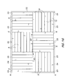
- FIG. 16 is a top view of the completed patio assembly of FIG. 15 ;
- FIG. 17 is an isometric view of a groundsheet and sleepers used in a third embodiment of the patio assembly
- FIGS. 18 and 19 are isometric views of a deck tile used in the third embodiment of the patio assembly.
- FIG. 20 is an isometric view of one corner of the third embodiment of the patio deck assembly during construction.
- FIG. 21 is an isometric view of the completed third embodiment of the patio deck.
- basic elements of the patio assembly include a groundsheet 1 formed of landscape fabric which can be rolled up to form a cylinder, a plurality of spaced apart, parallel sleepers 2 and 3 ( FIG. 2 ) permanently attached to the groundsheet using staples (not shown) or other fasteners, a plurality of spacers 4 , and a plurality of pre-assembled, rectangular deck tiles 6 ( FIGS. 3 and 4 ).
- An end sleeper 2 is attached to each end of the groundsheet 1 and the remaining central sleepers 3 are mounted on the groundsheet 1 between the end sleepers 2 .
- the spacers 4 are placed on the groundsheet 1 between the ends of the sleepers 2 and 3 .
- the spaces 4 stretch out the groundsheet 1 .
- each deck tile 6 includes three furring strips 7 and seven 1′′ ⁇ 6′′ floorboards 8 attached to the furring strips with 1 ⁇ 4′′ spacing between the boards.
- the deck tile 6 is assembled upside down, i.e. the floorboards 8 are placed on a flat surface and the furring strips 7 are nailed to the floorboard 8 using brad nails (not shown), which are not seen when the deck tile 6 is topside up.
- the furring strips 7 are connected to the ends of the boards 8 .
- hook and eye (Velcro®) fasteners are connected to the sleepers 2 and 3 , and to the deck tiles 6 .
- Halves 10 and 11 of the hook and eye fasteners are stapled to the end sleepers 2 and the central sleepers 3 , respectively, proximate the ends thereof.
- Fastener halves 12 are stapled to the middles of the sleepers 2 and 3 .
- the other halves 14 of the fasteners are stapled to the bottoms of the deck tiles 6 proximate the corners thereof.
- the fastener halves 14 When the deck panels 6 are mounted on the sleepers 2 and 3 , the fastener halves 14 are vertically aligned and become attached to the fastener halves 10 , 11 and 12 on the sleepers 2 and 3 . Whereas the fastener halves 10 and 14 are small rectangular strips, the fastener halves 11 and 12 are longer because they underlap the fastener halves 14 of two adjacent tiles 6 when the tiles are mounted on the sleepers 2 and 3 .
- the tiles 6 are mounted on the sleepers 2 and 3 one at a time, starting from one corner of the groundsheet to form the completed patio shown in FIG. 6 . Because the tiles 6 are attached to the sleepers 2 and 3 by hook and eye fasteners, the patio can quickly and easily be assembled and disassembled.
- a second embodiment of the patio assembly includes most of the basic elements of the assembly of FIGS. 1 to 6 .
- the deck assembly of FIGS. 1 to 6 is intended to be readily portable the assembly of FIGS. 7 to 16 is a more permanent structure, which once assembled remains in place indefinitely.
- the basic elements of the patio assembly of FIGS. 7 to 16 include a groundsheet 16 , parallel, spaced apart sleepers 17 and 18 permanently connected to the groundsheet using staples (not shown), a plurality of spacers 19 , pre-assembled deck tiles 6 ( FIGS. 3 and 4 ) and deck clips indicated generally at 20 .
- a narrow board 22 defining one end of a border is permanently mounted on and extends the length of each end sleeper 17 .
- Strips 23 of hook and eye fastener halves are attached to the ends of the sleepers 17 and 18 , and to the middle of end sleepers 17 .
- Four narrow boards 24 each having a length equal to one-half the distance between the end boards 22 are provided loose with the patio assembly.
- the boards 24 have a height equal to the thickness of the furring strips 7 and the deck boards 8 combined.
- the board 24 have pre-drilled holes 25 for receiving screws (not shown) when mounting the boards on the spacers 19 at the ends of the sleepers 17 and 18 .
- the ground sheet 16 is unrolled and the spacers 19 and the boards 24 are removed.
- the spacers 19 are placed in the position shown in phantom outline in FIG. 8 .
- a first of the boards 24 is placed above one side of the groundsheet 16 overlapping one end sleeper 17 and the end of one intermediate sleeper 18 .
- the outside of the board 24 is flush with the ends of the sleepers 17 and 18 , and with the outsides of the end spacers 19 .
- the thus positioned board 24 is then screwed to the spacers 19 .
- First and second deck tiles 6 are then positioned on the sleepers 17 and 18 against the boards 22 and 24 .
- a second board 24 is screwed to the adjacent spacers 19 along the outside edge of the second tile 6 to complete one-half of a border around the top of the patio assembly ( FIG. 10 ).
- a clip 20 is used to connect the inside corners of the first four of six deck tiles 6 to each other and to one of the intermediate sleepers 18 .
- the deck clip 20 is defined by a rectangular strip of material, one end 27 of which is bent to form an inverted L-shaped hook, which includes a top ledge 28 , which is connected to a large rectangular base 29 by a vertical web 30 .
- the ledge 28 extends horizontally from the top end of the web 30 in a direction away from the base 29 .
- Holes 32 are provided in the base 29 for receiving fasteners, which connect the slip 1 to a sleeper 18 ( FIGS. 12 to 14 ). Upwardly extending barbs 33 are punched out of the base 29 .
- the ledge 28 of the deck clip 20 is slid into a position in which one side of the ledge 28 overlaps the inner end of the furring strip 7 of one deck tile 6 and the side of the furring strip 7 of an adjacent deck tile 6 .
- the clip 20 is then connected to the intermediate sleeper 18 using fasteners in the form of screws 35 ( FIGS. 12 to 14 ).
- a third deck tile 6 ( FIG. 13 ) is placed in a position in which it overlaps approximately one-half of the base 29 of the clip 20 .
- the ends of the floorboards 8 of the third sleeper 6 are aligned with the longitudinal axis of the sleeper 18 .
- a fourth deck tile 6 ( FIG. 14 ) is then placed in position over the deck clip 20 with its floorboards 8 extending parallel to the longitudinal axis of the sleeper 18 .
- the corner of the fourth deck tile 6 is then pressed down so that the second prong 33 enters its furring strip 7 .
- a third board 24 is screwed to the spacers 19 in end-to-end relationship with the first board 24 .
- a second clip 20 is then mounted on the second intermediate sleeper 18 at the inner corners of the second and third deck tiles 6 and then the fifth and sixth deck tiles are attached to the second sleeper 18 in the same manner as the third and fourth tiles.
- a fourth board 24 is attached to the other ends of the sleepers 17 and 18 to complete the border around the tiles 6 . As shown in FIGS. 15 and 16 , the top of the deck tiles 8 is in the same plane as the top of the border.
- a relatively simple third embodiment of the invention includes a groundsheet 40 formed of landscape fabric ( FIG. 17 ), a plurality of spaced apart, parallel sleepers 41 and 42 permanently attached to the groundsheet using staples (not shown) or other fasteners, and a plurality of pre-assembled, square deck tiles 44 ( FIGS. 18 and 19 ).
- Narrow boards 45 defining end borders are permanently mounted on and extend the lengths of the end sleepers 42 .
- each deck tile 44 includes a square top plate or floorboard 46 , spacers 47 mounted on two opposite ends of the bottom of the floorboard and a strengthening strip 48 ( FIG. 19 ) mounted centrally on the bottom of the floorboard 46 .
- the spacers 47 are shorter than the sides of the floorboards 46 so that the sides of the floorboard extend beyond the ends of the spacers ( FIG. 18 ).
- the strip 48 ensures that there are no springy areas on a finished patio. While the floorboards 44 shown in FIGS. 18 to 21 are square, the floorboards can be rectangular.
- At least the top surfaces of the sleepers and the deck tiles are coated with a deck paint or another finish such as a vinyl covering available under the trademark DURADEK or a similar product. After the coating has been applied to the sleepers and the deck tiles, strips of hook and eye fasteners (not shown) are attached to the top surfaces of the sleepers and to the bottom corners of the tile floorboards.
- a deck paint or another finish such as a vinyl covering available under the trademark DURADEK or a similar product.
- the groundsheet 40 , sleepers 41 and 42 and the boards 45 would form a more or less cylindrical roll.
- the groundsheet 40 is unrolled ( FIG. 17 ), and, starting at one corner, the tiles 44 are mounted on the sleepers 41 and 42 .
- the sides fo the floorboards at the ends of the spacers 47 overlap the sleepers 41 and 42 .
- the length of each side of the floorboards is such that the floorboards overlap approximately one half the width of the sleeper 41 or 42 .
- the spacers 47 stretch out the groundsheet 40 and keep it flat on the ground. With all tiles 44 mounted on the sleepers 41 and 42 , the result is the patio shown in FIG. 21 .
Landscapes
- Engineering & Computer Science (AREA)
- Architecture (AREA)
- Civil Engineering (AREA)
- Structural Engineering (AREA)
- Physics & Mathematics (AREA)
- Electromagnetism (AREA)
- Floor Finish (AREA)
Abstract
Description
Claims (11)
Priority Applications (1)
| Application Number | Priority Date | Filing Date | Title |
|---|---|---|---|
| US15/731,595 US10011998B1 (en) | 2017-07-06 | 2017-07-06 | Modular patio assembly |
Applications Claiming Priority (1)
| Application Number | Priority Date | Filing Date | Title |
|---|---|---|---|
| US15/731,595 US10011998B1 (en) | 2017-07-06 | 2017-07-06 | Modular patio assembly |
Publications (1)
| Publication Number | Publication Date |
|---|---|
| US10011998B1 true US10011998B1 (en) | 2018-07-03 |
Family
ID=62684188
Family Applications (1)
| Application Number | Title | Priority Date | Filing Date |
|---|---|---|---|
| US15/731,595 Active US10011998B1 (en) | 2017-07-06 | 2017-07-06 | Modular patio assembly |
Country Status (1)
| Country | Link |
|---|---|
| US (1) | US10011998B1 (en) |
Cited By (7)
| Publication number | Priority date | Publication date | Assignee | Title |
|---|---|---|---|---|
| CN109083499A (en) * | 2018-11-09 | 2018-12-25 | 王蒙蒙 | A kind of novel building glass closure |
| US10214914B2 (en) * | 2016-12-14 | 2019-02-26 | Thomas W. Bachelder | Flooring system for and methods of installing decking material directly atop an installation surface |
| US20190383029A1 (en) * | 2018-06-14 | 2019-12-19 | Société en Commandite Prolam | Slip-resistant floor for a cargo-carrying apparatus |
| EP3620590A1 (en) * | 2018-09-06 | 2020-03-11 | Proposebois Nantes | Kit for applying a coating on a support such as a floor or wall |
| US11053694B1 (en) * | 2019-12-19 | 2021-07-06 | Robert B. Jordan, IV | Deck rejuvenation system and method |
| JP7288866B2 (en) | 2020-01-21 | 2023-06-08 | 三協立山株式会社 | outdoor furniture |
| USD1007009S1 (en) * | 2020-12-15 | 2023-12-05 | Fabricant De Poêles International Inc. | Floor covering panel |
Citations (21)
| Publication number | Priority date | Publication date | Assignee | Title |
|---|---|---|---|---|
| US4568587A (en) * | 1981-09-25 | 1986-02-04 | Balco, Inc. | Roll-up floor mat with rigid rails |
| US4622792A (en) * | 1984-05-31 | 1986-11-18 | Champion Building Systems, Inc. | Modular deck structure and method for constructing same |
| US5303526A (en) * | 1989-02-08 | 1994-04-19 | Robbins, Inc. | Resilient portable floor system |
| US5323575A (en) * | 1993-06-01 | 1994-06-28 | Yeh Tzung Jzng | Tile and mounting mat assembly |
| US5482755A (en) * | 1994-04-28 | 1996-01-09 | Manning; James H. | Readily attachable and detachable coverings for surfaces |
| US5486392A (en) * | 1994-07-05 | 1996-01-23 | Reese Enterprises, Inc. | Roll-up floor mat |
| US6182414B1 (en) * | 1999-03-30 | 2001-02-06 | Chin-Chih Huang | Wooden floorboard assembly |
| US6395362B1 (en) * | 1996-07-19 | 2002-05-28 | Tac-Fast Georgia, L.L.C. | Anchor sheet framework and subflooring |
| US6434779B1 (en) * | 1998-01-07 | 2002-08-20 | Construction Specialties, Inc. | Foot mat |
| US6460303B1 (en) * | 1996-07-19 | 2002-10-08 | Tac-Fast Georgia L.L.C. | Hook and loop anchor sheet module with overlapped edges and sufficient mass to resist buckling |
| US20030070391A1 (en) * | 2000-04-26 | 2003-04-17 | Tachauer Ernesto S. | Fastening with wide fastening membrane |
| US20050257483A1 (en) * | 2004-04-02 | 2005-11-24 | Lennart Wilhelmsson | Modular wooden decking for patios, balconies or terraces |
| US20060222804A1 (en) * | 2005-03-29 | 2006-10-05 | Murray Banting | Roll-up mat for roadways and the like |
| US7140156B1 (en) * | 2002-09-25 | 2006-11-28 | Dlh Nordisk, Inc. | System for installation of decking tiles |
| US20090266022A1 (en) * | 2008-04-28 | 2009-10-29 | Ling Chen Lin | Indoor/outdoor interlocking deck tile device |
| US20100251641A1 (en) * | 2009-04-07 | 2010-10-07 | Interface, Inc. | Systems and Methods for Modular Floor Installation |
| US20120090256A1 (en) * | 2010-10-14 | 2012-04-19 | Andrews Robin D | Three dimensional tiled deck accessories |
| US20130123033A1 (en) * | 2011-11-16 | 2013-05-16 | System-300 Group Oy | Temporary flooring structure |
| US9038324B2 (en) * | 2013-02-26 | 2015-05-26 | United Construction Products, Inc. | Field paver connector and restraining system |
| US20150345155A1 (en) * | 2013-01-28 | 2015-12-03 | Armstrong World Industries, Inc. | Flooring underlayment and apparatus, flooring system and floor installation method using the same |
| US9752326B2 (en) * | 2008-04-10 | 2017-09-05 | Velcro BVBA | Membrane roofing |
-
2017
- 2017-07-06 US US15/731,595 patent/US10011998B1/en active Active
Patent Citations (21)
| Publication number | Priority date | Publication date | Assignee | Title |
|---|---|---|---|---|
| US4568587A (en) * | 1981-09-25 | 1986-02-04 | Balco, Inc. | Roll-up floor mat with rigid rails |
| US4622792A (en) * | 1984-05-31 | 1986-11-18 | Champion Building Systems, Inc. | Modular deck structure and method for constructing same |
| US5303526A (en) * | 1989-02-08 | 1994-04-19 | Robbins, Inc. | Resilient portable floor system |
| US5323575A (en) * | 1993-06-01 | 1994-06-28 | Yeh Tzung Jzng | Tile and mounting mat assembly |
| US5482755A (en) * | 1994-04-28 | 1996-01-09 | Manning; James H. | Readily attachable and detachable coverings for surfaces |
| US5486392A (en) * | 1994-07-05 | 1996-01-23 | Reese Enterprises, Inc. | Roll-up floor mat |
| US6395362B1 (en) * | 1996-07-19 | 2002-05-28 | Tac-Fast Georgia, L.L.C. | Anchor sheet framework and subflooring |
| US6460303B1 (en) * | 1996-07-19 | 2002-10-08 | Tac-Fast Georgia L.L.C. | Hook and loop anchor sheet module with overlapped edges and sufficient mass to resist buckling |
| US6434779B1 (en) * | 1998-01-07 | 2002-08-20 | Construction Specialties, Inc. | Foot mat |
| US6182414B1 (en) * | 1999-03-30 | 2001-02-06 | Chin-Chih Huang | Wooden floorboard assembly |
| US20030070391A1 (en) * | 2000-04-26 | 2003-04-17 | Tachauer Ernesto S. | Fastening with wide fastening membrane |
| US7140156B1 (en) * | 2002-09-25 | 2006-11-28 | Dlh Nordisk, Inc. | System for installation of decking tiles |
| US20050257483A1 (en) * | 2004-04-02 | 2005-11-24 | Lennart Wilhelmsson | Modular wooden decking for patios, balconies or terraces |
| US20060222804A1 (en) * | 2005-03-29 | 2006-10-05 | Murray Banting | Roll-up mat for roadways and the like |
| US9752326B2 (en) * | 2008-04-10 | 2017-09-05 | Velcro BVBA | Membrane roofing |
| US20090266022A1 (en) * | 2008-04-28 | 2009-10-29 | Ling Chen Lin | Indoor/outdoor interlocking deck tile device |
| US20100251641A1 (en) * | 2009-04-07 | 2010-10-07 | Interface, Inc. | Systems and Methods for Modular Floor Installation |
| US20120090256A1 (en) * | 2010-10-14 | 2012-04-19 | Andrews Robin D | Three dimensional tiled deck accessories |
| US20130123033A1 (en) * | 2011-11-16 | 2013-05-16 | System-300 Group Oy | Temporary flooring structure |
| US20150345155A1 (en) * | 2013-01-28 | 2015-12-03 | Armstrong World Industries, Inc. | Flooring underlayment and apparatus, flooring system and floor installation method using the same |
| US9038324B2 (en) * | 2013-02-26 | 2015-05-26 | United Construction Products, Inc. | Field paver connector and restraining system |
Cited By (10)
| Publication number | Priority date | Publication date | Assignee | Title |
|---|---|---|---|---|
| US10214914B2 (en) * | 2016-12-14 | 2019-02-26 | Thomas W. Bachelder | Flooring system for and methods of installing decking material directly atop an installation surface |
| US20190383029A1 (en) * | 2018-06-14 | 2019-12-19 | Société en Commandite Prolam | Slip-resistant floor for a cargo-carrying apparatus |
| US12607021B2 (en) * | 2018-06-14 | 2026-04-21 | Société en Commandite Prolam | Slip-resistant floor for a cargo-carrying apparatus |
| EP3620590A1 (en) * | 2018-09-06 | 2020-03-11 | Proposebois Nantes | Kit for applying a coating on a support such as a floor or wall |
| FR3085693A1 (en) * | 2018-09-06 | 2020-03-13 | Proposebois Nantes | KIT FOR LAYING A COVERING ON A FLOOR OR WALL TYPE SUPPORT |
| CN109083499A (en) * | 2018-11-09 | 2018-12-25 | 王蒙蒙 | A kind of novel building glass closure |
| US11053694B1 (en) * | 2019-12-19 | 2021-07-06 | Robert B. Jordan, IV | Deck rejuvenation system and method |
| US11993940B1 (en) * | 2019-12-19 | 2024-05-28 | Robert B. Jordan, IV | Deck rejuvenation system and method |
| JP7288866B2 (en) | 2020-01-21 | 2023-06-08 | 三協立山株式会社 | outdoor furniture |
| USD1007009S1 (en) * | 2020-12-15 | 2023-12-05 | Fabricant De Poêles International Inc. | Floor covering panel |
Similar Documents
| Publication | Publication Date | Title |
|---|---|---|
| US10011998B1 (en) | Modular patio assembly | |
| US9145673B1 (en) | Deck clip and modular deck assembly | |
| US2129975A (en) | Acoustical tile clip | |
| US4221095A (en) | Wall constructed from wallboard held together with concealed fasteners | |
| US4238915A (en) | Tile setting assembly, tile wall and method for building a tile wall | |
| JP5599191B2 (en) | Building system | |
| US6449913B1 (en) | Parquet flooring panel comprising spaced, wooden strips secured by adhesive and forming irregular end shapes for alignment with adjacent panels | |
| CA2676653C (en) | Wall panel system | |
| US7748190B1 (en) | Cleat | |
| CA2509824A1 (en) | Cladding assembly and method of cladding posts | |
| KR20090117289A (en) | Combination system of tech materials with channel clip | |
| CA2893389A1 (en) | Fencing system | |
| RU143969U1 (en) | FACADE FACING MODULE (OPTIONS) | |
| US20120227348A1 (en) | Building Means | |
| US20100107534A1 (en) | Modular layout form for embedding objects in a settable material | |
| RU2007120756A (en) | FLOOR COVERING SYSTEM HAVING MANY PLACES OF COMBINATION | |
| CA2972602C (en) | Modular patio assembly | |
| US20200063438A1 (en) | Ventilated thin brick panel system | |
| US5058349A (en) | Surface tile for flooring and the like | |
| US20090282771A1 (en) | Panelling system primarily for decking | |
| US20080083187A1 (en) | Split tile for attachment to a building structure | |
| JP5837921B2 (en) | Partial structure for supporting floor and floor system including the partial structure | |
| JP4282748B1 (en) | Lattice body and assembly method thereof | |
| WO2016001886A1 (en) | A support arrangement for a structural lining | |
| US20210164236A1 (en) | Clip Attachment for Panel System |
Legal Events
| Date | Code | Title | Description |
|---|---|---|---|
| STCF | Information on status: patent grant |
Free format text: PATENTED CASE |
|
| FEPP | Fee payment procedure |
Free format text: MAINTENANCE FEE REMINDER MAILED (ORIGINAL EVENT CODE: REM.); ENTITY STATUS OF PATENT OWNER: SMALL ENTITY |
|
| FEPP | Fee payment procedure |
Free format text: SURCHARGE FOR LATE PAYMENT, SMALL ENTITY (ORIGINAL EVENT CODE: M2554); ENTITY STATUS OF PATENT OWNER: SMALL ENTITY |
|
| MAFP | Maintenance fee payment |
Free format text: PAYMENT OF MAINTENANCE FEE, 4TH YR, SMALL ENTITY (ORIGINAL EVENT CODE: M2551); ENTITY STATUS OF PATENT OWNER: SMALL ENTITY Year of fee payment: 4 |
|
| FEPP | Fee payment procedure |
Free format text: MAINTENANCE FEE REMINDER MAILED (ORIGINAL EVENT CODE: REM.); ENTITY STATUS OF PATENT OWNER: SMALL ENTITY |