TWI793799B - Imaging lens assembly module and electronic device - Google Patents
Imaging lens assembly module and electronic device Download PDFInfo
- Publication number
- TWI793799B TWI793799B TW110138063A TW110138063A TWI793799B TW I793799 B TWI793799 B TW I793799B TW 110138063 A TW110138063 A TW 110138063A TW 110138063 A TW110138063 A TW 110138063A TW I793799 B TWI793799 B TW I793799B
- Authority
- TW
- Taiwan
- Prior art keywords
- optical axis
- imaging lens
- lens
- reducing
- reduction
- Prior art date
Links
- 238000003384 imaging method Methods 0.000 title claims abstract description 223
- 230000003287 optical effect Effects 0.000 claims abstract description 181
- 239000000758 substrate Substances 0.000 claims abstract description 26
- 239000003292 glue Substances 0.000 claims description 25
- 238000013459 approach Methods 0.000 claims description 3
- 235000012149 noodles Nutrition 0.000 claims 1
- 238000010586 diagram Methods 0.000 description 23
- 238000004519 manufacturing process Methods 0.000 description 11
- 238000000034 method Methods 0.000 description 7
- 238000009434 installation Methods 0.000 description 6
- 230000000875 corresponding effect Effects 0.000 description 5
- 230000009286 beneficial effect Effects 0.000 description 4
- 238000002310 reflectometry Methods 0.000 description 4
- 230000007423 decrease Effects 0.000 description 1
- 238000013461 design Methods 0.000 description 1
- 238000005516 engineering process Methods 0.000 description 1
- 238000012986 modification Methods 0.000 description 1
- 230000004048 modification Effects 0.000 description 1
- 238000012545 processing Methods 0.000 description 1
Images


Classifications
-
- G—PHYSICS
- G02—OPTICS
- G02B—OPTICAL ELEMENTS, SYSTEMS OR APPARATUS
- G02B13/00—Optical objectives specially designed for the purposes specified below
- G02B13/001—Miniaturised objectives for electronic devices, e.g. portable telephones, webcams, PDAs, small digital cameras
- G02B13/0015—Miniaturised objectives for electronic devices, e.g. portable telephones, webcams, PDAs, small digital cameras characterised by the lens design
- G02B13/002—Miniaturised objectives for electronic devices, e.g. portable telephones, webcams, PDAs, small digital cameras characterised by the lens design having at least one aspherical surface
- G02B13/004—Miniaturised objectives for electronic devices, e.g. portable telephones, webcams, PDAs, small digital cameras characterised by the lens design having at least one aspherical surface having four lenses
-
- G—PHYSICS
- G02—OPTICS
- G02B—OPTICAL ELEMENTS, SYSTEMS OR APPARATUS
- G02B13/00—Optical objectives specially designed for the purposes specified below
- G02B13/001—Miniaturised objectives for electronic devices, e.g. portable telephones, webcams, PDAs, small digital cameras
- G02B13/0055—Miniaturised objectives for electronic devices, e.g. portable telephones, webcams, PDAs, small digital cameras employing a special optical element
- G02B13/0065—Miniaturised objectives for electronic devices, e.g. portable telephones, webcams, PDAs, small digital cameras employing a special optical element having a beam-folding prism or mirror
-
- G—PHYSICS
- G02—OPTICS
- G02B—OPTICAL ELEMENTS, SYSTEMS OR APPARATUS
- G02B7/00—Mountings, adjusting means, or light-tight connections, for optical elements
- G02B7/02—Mountings, adjusting means, or light-tight connections, for optical elements for lenses
- G02B7/021—Mountings, adjusting means, or light-tight connections, for optical elements for lenses for more than one lens
-
- G—PHYSICS
- G02—OPTICS
- G02B—OPTICAL ELEMENTS, SYSTEMS OR APPARATUS
- G02B5/00—Optical elements other than lenses
- G02B5/20—Filters
- G02B5/208—Filters for use with infrared or ultraviolet radiation, e.g. for separating visible light from infrared and/or ultraviolet radiation
Abstract
Description
本揭示內容係關於一種成像鏡頭模組,且特別是一種應用在可攜式電子裝置上的成像鏡頭模組。The disclosure relates to an imaging lens module, and in particular to an imaging lens module applied to a portable electronic device.
近年來,可攜式電子裝置發展快速,例如智慧型電子裝置、平板電腦、筆記型電腦等,已充斥在現代人的生活中,而裝載在可攜式電子裝置上的成像鏡頭模組也隨之蓬勃發展。但隨著科技愈來愈進步,使用者對於成像鏡頭模組的品質要求也愈來愈高。In recent years, portable electronic devices have developed rapidly, such as smart electronic devices, tablet computers, notebook computers, etc., which have flooded the lives of modern people, and imaging lens modules loaded on portable electronic devices have also followed suit. of flourishing. However, with the advancement of technology, users have higher and higher requirements for the quality of imaging lens modules.
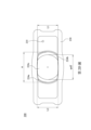
請參照第5A圖與第5B圖,其中第5A圖繪示依照現有技術中鏡筒50的示意圖,第5B圖繪示依照第5A圖現有技術中鏡筒50的另一示意圖。由第5A圖與第5B圖可知,現有技術中的鏡筒50的筒狀部51與底座部52為一體成型,而現有技術中的鏡筒50占用安裝的空間,以致於不利成像鏡頭模組的微小化。因此,發展一種可實現微小化並兼顧成像品質的成像鏡頭模組遂成為產業上重要且急欲解決的問題。Please refer to FIG. 5A and FIG. 5B , wherein FIG. 5A shows a schematic diagram of the
本揭示內容提供一種成像鏡頭模組與電子裝置,藉由設置縮減面於透鏡與鏡筒以壓縮成像鏡頭模組於垂直光軸的方向上的尺寸,進而實現成像鏡頭模組的微小化。藉此,於有限的空間中仍可安裝成像鏡頭,並維持成像品質。The present disclosure provides an imaging lens module and an electronic device. By arranging a reduction surface on the lens and lens barrel to compress the size of the imaging lens module in the direction perpendicular to the optical axis, the miniaturization of the imaging lens module is realized. In this way, the imaging lens can still be installed in a limited space, and the imaging quality can be maintained.
依據本揭示內容一實施方式提供一種成像鏡頭模組,包含一基板與一成像鏡頭。基板包含一感光元件。光軸通過成像鏡頭,且成像鏡頭包含一成像透鏡組與一鏡筒。成像透鏡組包含至少一透鏡。透鏡包含二第一縮減面,其中第一縮減面對稱於光軸設置,且第一縮減面自透鏡的一外緣面朝靠近光軸的方向縮減,使透鏡沿光軸觀察的輪廓呈非圓形。鏡筒包含一筒狀部與一底座部。筒狀部具有一第一內表面用以定義一第一內部空間,成像透鏡組設置於第一內部空間,且筒狀部包含二第二縮減面。第二縮減面對稱於光軸設置,第二縮減面設置於第一內表面對應第一縮減面的位置,第二縮減面自第一內表面朝靠近光軸的方向縮減,使第一內表面沿光軸觀察的輪廓呈非圓形。底座部具有一第二內表面用以定義一第二內部空間,且底座部自筒狀部沿光軸延伸並與基板實體接觸,使筒狀部與一成像面維持一固定距離。筒狀部與底座部為一體成型,透鏡的第一縮減面之間具有一最短間距,筒狀部的第二縮減面之間具有一最短間距,光軸垂直通過第一縮減面之間的最短間距與第二縮減面之間的最短間距,第一縮減面之間的最短間距為L1,第二縮減面之間的最短間距為L2,透鏡的一直徑為φ,其滿足下列條件:L1 ≤ L2 < φ。According to an embodiment of the present disclosure, an imaging lens module is provided, which includes a substrate and an imaging lens. The substrate includes a photosensitive element. The optical axis passes through the imaging lens, and the imaging lens includes an imaging lens group and a lens barrel. The imaging lens group includes at least one lens. The lens includes two first reducing surfaces, wherein the first reducing surface is arranged symmetrically to the optical axis, and the first reducing surface is reduced from an outer edge surface of the lens toward a direction close to the optical axis, so that the outline of the lens viewed along the optical axis is non-circular shape. The lens barrel includes a cylindrical portion and a base portion. The cylindrical portion has a first inner surface for defining a first inner space, the imaging lens group is disposed in the first inner space, and the cylindrical portion includes two second reducing surfaces. The second reduction surface is arranged symmetrically with respect to the optical axis, and the second reduction surface is arranged at the position corresponding to the first reduction surface on the first inner surface, and the second reduction surface is reduced from the first inner surface toward the direction close to the optical axis, so that the first inner surface The profile viewed along the optical axis is non-circular. The base part has a second inner surface for defining a second inner space, and the base part extends from the cylindrical part along the optical axis and is in physical contact with the substrate, so that the cylindrical part maintains a fixed distance from an imaging surface. The cylindrical part and the base part are integrally formed, there is a shortest distance between the first reducing surfaces of the lens, there is a shortest distance between the second reducing surfaces of the cylindrical part, and the optical axis passes through the shortest distance between the first reducing surfaces vertically. The shortest distance between the spacing and the second reduction surface, the shortest distance between the first reduction surface is L1, the shortest distance between the second reduction surface is L2, and the first diameter of the lens is φ, which satisfies the following conditions: L1 ≤ L2<φ.
依據前段所述實施方式的成像鏡頭模組,其中鏡筒的底座部沿光軸的一高度為H1,鏡筒整體沿光軸的一高度為H,其可滿足下列條件:0.13 < H1/H < 0.84。According to the imaging lens module described in the preceding paragraph, a height of the base portion of the lens barrel along the optical axis is H1, and a height of the entire lens barrel along the optical axis is H, which can satisfy the following conditions: 0.13<H1/H < 0.84.
依據前段所述實施方式的成像鏡頭模組,其中第一縮減面之間的最短間距為L1,透鏡的直徑為φ,其可滿足下列條件:0.5 < L1/φ < 0.8。According to the imaging lens module described in the preceding paragraph, the shortest distance between the first reducing surfaces is L1, and the diameter of the lens is φ, which can satisfy the following conditions: 0.5 < L1/φ < 0.8.
依據前段所述實施方式的成像鏡頭模組,其中底座部可包含二第三縮減面,第三縮減面對稱於光軸設置,第三縮減面設置於第二內表面,且第三縮減面自第二內表面朝靠近光軸的方向縮減,使底座部沿光軸觀察的輪廓呈非圓形。According to the imaging lens module of the embodiment described in the previous paragraph, wherein the base part may include two third reduction surfaces, the third reduction surface is arranged symmetrically to the optical axis, the third reduction surface is arranged on the second inner surface, and the third reduction surface is formed from The second inner surface shrinks toward the direction close to the optical axis, so that the outline of the base part viewed along the optical axis is non-circular.
依據前段所述實施方式的成像鏡頭模組,其中底座部可更包含一消光層,且消光層設置於第二內表面。According to the imaging lens module of the above-mentioned embodiment, the base portion may further include a matte layer, and the matte layer is disposed on the second inner surface.
依據前段所述實施方式的成像鏡頭模組,其中底座部可包含一紅外濾光片,紅外濾光片設置於第二內部空間。According to the imaging lens module described in the preceding paragraph, the base portion may include an infrared filter, and the infrared filter is disposed in the second inner space.
依據前段所述實施方式的成像鏡頭模組,其中底座部可包含一逃氣口,逃氣口連通第二內部空間與鏡筒的一外部空間,逃氣口沿平行光軸的方向延伸,且逃氣口由筒狀部往底座部漸縮。According to the imaging lens module of the embodiment described in the preceding paragraph, wherein the base part may include an air escape port, the air escape port communicates with the second internal space and an external space of the lens barrel, the air escape port extends in a direction parallel to the optical axis, and the air escape port is formed by The cylindrical portion tapers toward the base portion.
依據前段所述實施方式的成像鏡頭模組,其中成像透鏡組的透鏡的數量可為複數,透鏡中最像側的一透鏡可包含第一縮減面。According to the imaging lens module described in the preceding paragraph, the number of lenses in the imaging lens group may be plural, and the most image-side lens among the lenses may include a first reduction surface.
依據前段所述實施方式的成像鏡頭模組,其中鏡筒可更包含二第四縮減面,第四縮減面對稱於光軸設置,第四縮減面設置於鏡筒的一外表面,第四縮減面自鏡筒的外表面朝靠近光軸的方向縮減,且第四縮減面由筒狀部沿光軸延伸至底座部,使鏡筒沿光軸觀察的輪廓呈非圓形。According to the imaging lens module of the embodiment described in the preceding paragraph, wherein the lens barrel may further include two fourth reduction surfaces, the fourth reduction surface is arranged symmetrically to the optical axis, the fourth reduction surface is arranged on an outer surface of the lens barrel, and the fourth reduction surface The surface decreases from the outer surface of the lens barrel toward the direction close to the optical axis, and the fourth reducing surface extends from the cylindrical portion along the optical axis to the base portion, so that the outline of the lens barrel viewed along the optical axis is non-circular.
依據前段所述實施方式的成像鏡頭模組,其中由最像側的透鏡往物側的相鄰至少二透鏡可包含第一縮減面。According to the imaging lens module described in the preceding paragraph, at least two adjacent lenses from the most image-side lens to the object side may include a first reduction surface.
依據前段所述實施方式的成像鏡頭模組,其中最物側至最像側的每一透鏡可分別包含第一縮減面。According to the imaging lens module of the embodiment described in the preceding paragraph, each lens from the most object side to the most image side may respectively include a first reduction surface.
依據前段所述實施方式的成像鏡頭模組,其中鏡筒的第四縮減面之間於最像側具有一第一最短寬度,光軸垂直通過第一最短寬度,第一最短寬度為W1,其可滿足下列條件:0.8 mm < W1 < 2.2 mm。According to the imaging lens module of the embodiment described in the previous paragraph, wherein the fourth reduction surface of the lens barrel has a first shortest width on the most image side, the optical axis passes through the first shortest width vertically, and the first shortest width is W1, which The following conditions can be met: 0.8 mm < W1 < 2.2 mm.
依據前段所述實施方式的成像鏡頭模組,其中鏡筒的第四縮減面之間於最像側具有一第一最短寬度,鏡筒的第四縮減面之間於最物側具有一第二最短寬度,光軸垂直通過第一最短寬度與第二最短寬度,第一最短寬度與第二最短寬度之間具有一寬度差,第一最短寬度為W1,第二最短寬度為W2,寬度差為ΔW,其可滿足下列條件:ΔW = ∣W1-W2∣;以及0.005 mm < ΔW/2 < 0.2 mm。According to the imaging lens module of the embodiment described in the previous paragraph, the fourth reduction surface of the lens barrel has a first shortest width on the most image side, and the fourth reduction surface of the lens barrel has a second shortest width on the most object side. The shortest width, the optical axis passes through the first shortest width and the second shortest width vertically, there is a width difference between the first shortest width and the second shortest width, the first shortest width is W1, the second shortest width is W2, and the width difference is ΔW, which can satisfy the following conditions: ΔW = ∣W1-W2∣; and 0.005 mm < ΔW/2 < 0.2 mm.
依據前段所述實施方式的成像鏡頭模組,其中鏡筒的第四縮減面之間於最物側具有一第二最短寬度,光軸垂直通過第二最短寬度,第一最短寬度為W1,第二最短寬度為W2,其可滿足下列條件:0.7 mm < (W1+W2)/2 < 2.1 mm。According to the imaging lens module of the embodiment described in the preceding paragraph, wherein the fourth reduction surface of the lens barrel has a second shortest width on the most object side, the optical axis passes through the second shortest width vertically, the first shortest width is W1, and the second shortest width is W1. 2. The shortest width is W2, which can meet the following conditions: 0.7 mm < (W1+W2)/2 < 2.1 mm.
依據前段所述實施方式的成像鏡頭模組,其中透鏡中最像側的透鏡可透過一點膠方式與鏡筒連接。According to the imaging lens module of the embodiment described in the preceding paragraph, the lens on the most image side among the lenses can be connected to the lens barrel through a little glue.
依據前段所述實施方式的成像鏡頭模組,其中透鏡可分別包含一邊緣部與一光學有效部,邊緣部較光學有效部遠離光軸,光學有效部可具有光線屈折力,第一縮減面使光學有效部沿光軸觀察的輪廓呈非圓形。第一縮減面之間的最短間距為L1,各透鏡的光學有效部的一直徑為φeff,其可滿足下列條件:L1 < φeff。In the imaging lens module according to the embodiment described in the preceding paragraph, the lens may respectively include an edge portion and an optical effective portion, the edge portion is farther from the optical axis than the optical effective portion, the optical effective portion may have light refraction power, and the first reduction surface uses The outline of the optically effective portion viewed along the optical axis is non-circular. The shortest distance between the first reducing surfaces is L1, and a diameter of the optically effective portion of each lens is φeff, which can satisfy the following condition: L1<φeff.
依據前段所述實施方式的成像鏡頭模組,其中第一縮減面與第二縮減面可間隔設置,第一縮減面之間的最短間距為L1,第二縮減面之間的最短間距為L2,其可滿足下列條件:L1 < L2。According to the imaging lens module of the embodiment described in the preceding paragraph, wherein the first reduction surface and the second reduction surface can be arranged at intervals, the shortest distance between the first reduction surfaces is L1, and the shortest distance between the second reduction surfaces is L2, It can satisfy the following condition: L1 < L2.
依據前段所述實施方式的成像鏡頭模組,可更包含一光路轉折元件,其中光路轉折元件用以導引一光線至成像鏡頭。The imaging lens module according to the above-mentioned embodiment may further include an optical path turning element, wherein the optical path turning element is used to guide a light to the imaging lens.
依據本揭示內容一實施方式提供一種電子裝置,包含一面板螢幕與如前述實施方式的成像鏡頭模組,其中成像鏡頭模組設置於靠近面板螢幕的周圍,且面板螢幕所佔電子裝置的一屏佔比為92%以上。According to an embodiment of the present disclosure, an electronic device is provided, which includes a panel screen and the imaging lens module as in the foregoing embodiment, wherein the imaging lens module is disposed near the periphery of the panel screen, and the panel screen occupies one screen of the electronic device. The proportion is more than 92%.
依據前段所述實施方式的電子裝置,其中面板螢幕所佔電子裝置的屏佔比可為95%以上。According to the electronic device described in the preceding paragraph, the panel screen can account for more than 95% of the screen-to-body ratio of the electronic device.
依據前段所述實施方式的電子裝置,其中電子裝置可為一筆記型電腦。According to the electronic device described in the preceding paragraph, the electronic device may be a notebook computer.
本揭示內容提供一種成像鏡頭模組,包含一基板與一成像鏡頭。基板包含一感光元件。一光軸通過成像鏡頭,且成像鏡頭包含一成像透鏡組與一鏡筒。成像透鏡組包含至少一透鏡,且透鏡包含二第一縮減面,其中第一縮減面對稱於光軸設置,且第一縮減面自透鏡的一外緣面朝靠近光軸的方向縮減,使透鏡沿光軸觀察的輪廓呈非圓形。鏡筒包含一筒狀部與一底座部。筒狀部具有一第一內表面用以定義一第一內部空間,成像透鏡組設置於第一內部空間,且筒狀部包含二第二縮減面,其中第二縮減面對稱於光軸設置,第二縮減面設置於第一內表面對應第一縮減面的位置,第二縮減面自第一內表面朝靠近光軸的方向縮減,使第一內表面沿光軸觀察的輪廓呈非圓形。底座部具有一第二內表面用以定義一第二內部空間,且底座部自筒狀部沿光軸延伸並與基板實體接觸,使筒狀部與一成像面維持一固定距離。鏡筒的筒狀部與底座部為一體成型,透鏡的第一縮減面之間具有一最短間距,筒狀部的第二縮減面之間具有一最短間距,光軸垂直通過第一縮減面之間的最短間距與第二縮減面之間的最短間距,第一縮減面之間的最短間距為L1,第二縮減面之間的最短間距為L2,透鏡的一直徑為φ,其滿足下列條件:L1 ≤ L2 < φ。The disclosure provides an imaging lens module, which includes a substrate and an imaging lens. The substrate includes a photosensitive element. An optical axis passes through the imaging lens, and the imaging lens includes an imaging lens group and a lens barrel. The imaging lens group includes at least one lens, and the lens includes two first reducing surfaces, wherein the first reducing surface is arranged symmetrically to the optical axis, and the first reducing surface is reduced from an outer edge surface of the lens toward a direction close to the optical axis, so that the lens The profile viewed along the optical axis is non-circular. The lens barrel includes a cylindrical portion and a base portion. The cylindrical portion has a first inner surface for defining a first internal space, the imaging lens group is disposed in the first internal space, and the cylindrical portion includes two second reducing surfaces, wherein the second reducing surfaces are arranged symmetrically to the optical axis, The second reduction surface is arranged at the position where the first inner surface corresponds to the first reduction surface, and the second reduction surface shrinks from the first inner surface toward the direction close to the optical axis, so that the outline of the first inner surface viewed along the optical axis is non-circular. . The base part has a second inner surface for defining a second inner space, and the base part extends from the cylindrical part along the optical axis and is in physical contact with the substrate, so that the cylindrical part maintains a fixed distance from an imaging surface. The cylindrical part of the lens barrel and the base part are integrally formed, there is a shortest distance between the first reducing surfaces of the lens, there is a shortest distance between the second reducing surfaces of the cylindrical part, and the optical axis passes through the first reducing surface vertically The shortest distance between the shortest distance between and the second reduction surface, the shortest distance between the first reduction surface is L1, the shortest distance between the second reduction surface is L2, a diameter of the lens is φ, which meets the following conditions : L1 ≤ L2 < φ.
透過一體成型的筒狀部與底座部可減少成像鏡頭模組的組裝程序,以提升生產效率,並可避免習知技術的成像鏡頭與底座部安裝時產生的歪斜誤差。具體而言,鏡筒可為無螺牙結構,並可通過底座部的底面直接與基板連接固定。The integral forming of the cylindrical part and the base part can reduce the assembling process of the imaging lens module, so as to improve the production efficiency, and avoid the skew error generated when the imaging lens and the base part are installed in the prior art. Specifically, the lens barrel may have a screwless structure, and may be directly connected and fixed to the base plate through the bottom surface of the base portion.
再者,透過透鏡的第一縮減面與筒狀部的第二縮減面,可使成像鏡頭模組在垂直光軸的方向上的尺寸縮小,藉以實現成像鏡頭模組微小化,換言之,於有限的空間中仍可安裝成像鏡頭模組。進一步來說,第一縮減面與第二縮減面可為平面、曲面或二者之組合。Furthermore, through the first reducing surface of the lens and the second reducing surface of the cylindrical portion, the size of the imaging lens module in the direction perpendicular to the optical axis can be reduced, so as to realize the miniaturization of the imaging lens module. The imaging lens module can still be installed in the space. Further, the first reducing surface and the second reducing surface can be plane, curved or a combination of both.
成像鏡頭模組可為筆記型電腦的成像鏡頭模組或行動裝置的成像鏡頭模組,但不以此為限。The imaging lens module can be an imaging lens module of a notebook computer or an imaging lens module of a mobile device, but not limited thereto.
底座部可包含二第三縮減面,其中第三縮減面對稱於光軸設置,第三縮減面設置於第二內表面,且第三縮減面自第二內表面朝靠近光軸的方向縮減,使底座部沿光軸觀察的輪廓呈非圓形。藉此,可使鏡筒在垂直光軸的方向上進一步壓縮尺寸,減少安裝於基板所需的空間。具體而言,第三縮減面可為平面、曲面或二者之組合。The base portion may include two third reduction surfaces, wherein the third reduction surface is disposed symmetrically to the optical axis, the third reduction surface is disposed on the second inner surface, and the third reduction surface is reduced from the second inner surface toward the direction close to the optical axis, The contour of the base portion viewed along the optical axis is made non-circular. In this way, the size of the lens barrel can be further reduced in the direction perpendicular to the optical axis, reducing the space required for installation on the substrate. Specifically, the third reducing surface can be a plane, a curved surface or a combination of the two.
底座部可更包含一消光層,其中消光層設置於第二內表面。藉此,可避免非成像光線在底座部的內部發生反射,影響成像品質。具體而言,消光層可為抗反射結構,或者可經過噴砂處理或鍍膜處理,但不以此為限。The base portion may further include a matte layer, wherein the matte layer is disposed on the second inner surface. In this way, the reflection of the non-imaging light inside the base part can be avoided, which will affect the imaging quality. Specifically, the matting layer may be an anti-reflection structure, or may be sandblasted or coated, but not limited thereto.
底座部可包含一紅外濾光片,其中紅外濾光片設置於第二內部空間。藉此,可濾除紅外光以提升成像品質。The base part may include an infrared filter, wherein the infrared filter is disposed in the second internal space. In this way, infrared light can be filtered to improve image quality.
底座部可包含一逃氣口,其中逃氣口連通第二內部空間與鏡筒的一外部空間,逃氣口沿平行光軸的方向延伸,且逃氣口由筒狀部往底座部漸縮。透過逃氣口連通鏡筒的第二內部空間與外部空間以平衡壓力,避免組裝過程中成像鏡頭模組因內部氣壓導致成像鏡頭模組的偏移。The base portion may include an air escape port, wherein the air escape port communicates with the second inner space and an external space of the lens barrel, the air escape port extends along a direction parallel to the optical axis, and the air escape port tapers from the cylindrical portion to the base portion. The second internal space and the external space of the lens barrel are connected through the air escape port to balance the pressure, so as to prevent the imaging lens module from shifting due to the internal air pressure during the assembly process.
成像透鏡組的透鏡的數量可為複數,其中透鏡中最像側的一透鏡包含第一縮減面。藉此,有利於實現成像鏡頭模組的微小化。具體而言,由最大直徑的透鏡開始設置第一縮減面。The number of lenses in the imaging lens group may be plural, and one lens on the most image side of the lenses includes a first reduction surface. Thereby, it is beneficial to realize the miniaturization of the imaging lens module. Specifically, the first reduction surface is provided starting from the lens with the largest diameter.
鏡筒可更包含二第四縮減面,其中第四縮減面對稱於光軸設置,第四縮減面設置於鏡筒的一外表面,第四縮減面自鏡筒的外表面朝靠近光軸的方向縮減,且第四縮減面由筒狀部沿光軸延伸至底座部,使鏡筒沿光軸觀察的輪廓呈非圓形。具體而言,第四縮減面可為平面、曲面或二者之組合。The lens barrel may further include two fourth reducing surfaces, wherein the fourth reducing surface is arranged symmetrically to the optical axis, the fourth reducing surface is arranged on an outer surface of the lens barrel, and the fourth reducing surface is from the outer surface of the lens barrel toward a direction close to the optical axis. The direction is reduced, and the fourth reduction surface extends from the cylindrical portion to the base portion along the optical axis, so that the outline of the lens barrel viewed along the optical axis is non-circular. Specifically, the fourth reducing surface can be a plane, a curved surface or a combination of the two.
由最像側的透鏡往物側的相鄰至少二透鏡可包含第一縮減面。藉此,可應用於窄邊框的筆記型電腦,但並不以此應用為限。At least two adjacent lenses from the most image-side lens to the object side may include a first reduction surface. In this way, it can be applied to notebook computers with narrow borders, but the application is not limited thereto.
最物側至最像側的每一透鏡可分別包含第一縮減面。藉此,可在垂直光軸的方向上進一步縮小成像鏡頭模組的尺寸。具體而言,於最物側的透鏡至最像側的透鏡皆包含第一縮減面的情況下,同時要維持成像鏡頭模組的成像品質,並需要高生產良率。再者,成像透鏡組可更包含遮光元件與固定元件,其中遮光元件與固定元件皆包含縮減部。Each lens from the most object side to the most image side may respectively include a first reduction surface. Thereby, the size of the imaging lens module can be further reduced in the direction perpendicular to the optical axis. Specifically, in the case that the lens on the most object side to the lens on the most image side all include the first reducing surface, at the same time, the imaging quality of the imaging lens module needs to be maintained, and a high production yield is required. Furthermore, the imaging lens group may further include a shading element and a fixed element, wherein both the shading element and the fixing element include a reduction portion.
透鏡中最像側的透鏡可透過一點膠方式與鏡筒連接。透過點膠方式固定透鏡可提升生產效率,並增加組裝穩固性。具體而言,點膠方式的膠水可為黑色膠水,可降低非成像光線的反射率。再者,鏡筒的內表面可以設置點膠結構,並可透過影像辨識判斷填膠情況。The lens on the most image side of the lens can be connected to the lens barrel through a little glue. Fixing the lens by dispensing can improve production efficiency and increase assembly stability. Specifically, the glue in the way of dispensing can be black glue, which can reduce the reflectivity of non-imaging light. Furthermore, the inner surface of the lens barrel can be provided with a glue dispensing structure, and the glue filling situation can be judged through image recognition.
成像鏡頭模組可更包含一光路轉折元件,其中光路轉折元件用以導引一光線至成像鏡頭。具體來說,光路轉折元件可為稜鏡或反射鏡,並可設置於成像鏡頭與入光口之間,但並不以此為限。The imaging lens module may further include an optical path turning element, wherein the optical path turning element is used to guide a light to the imaging lens. Specifically, the light path turning element can be a mirror or a mirror, and can be arranged between the imaging lens and the light entrance, but not limited thereto.
鏡筒的底座部沿光軸的一高度為H1,鏡筒整體沿光軸的一高度為H,其可滿足下列條件:0.13 < H1/H < 0.84。透過調整底座部的高度以因應各種組裝或光學需求。A height of the base of the lens barrel along the optical axis is H1, and a height of the entire lens barrel along the optical axis is H, which can satisfy the following conditions: 0.13 < H1/H < 0.84. By adjusting the height of the base part to meet various assembly or optical requirements.
第一縮減面之間的最短間距為L1,透鏡的直徑為φ,其可滿足下列條件:0.5 < L1/φ < 0.8。藉此,有利於成像鏡頭微小化,並維持光學性能。The shortest distance between the first reducing surfaces is L1, and the diameter of the lens is φ, which can satisfy the following conditions: 0.5 < L1/φ < 0.8. Thereby, it is beneficial to the miniaturization of the imaging lens and maintains the optical performance.
鏡筒的第四縮減面之間於最像側具有最短的一第一寬度,光軸垂直通過第一寬度,第一寬度為W1,其可滿足下列條件:0.8 mm < W1 < 2.2 mm。藉此,於有限的基板空間仍可安裝成像鏡頭。The fourth reducing surface of the lens barrel has the shortest first width on the most image side, the optical axis passes through the first width vertically, and the first width is W1, which can satisfy the following conditions: 0.8 mm < W1 < 2.2 mm. In this way, the imaging lens can still be installed in the limited substrate space.
鏡筒的第四縮減面之間於最物側具有最短的一第二寬度,光軸垂直通過第二寬度,第一寬度與第二寬度之間具有一寬度差,第一寬度為W1,第二寬度為W2,寬度差為ΔW,其可滿足下列條件:ΔW = ∣W1-W2∣;以及0.005 mm < ΔW/2 < 0.2 mm。透過鏡筒的外表面無大變化的結構起伏,可有效利用安裝空間。The fourth reduction surface of the lens barrel has the shortest second width on the most object side, the optical axis passes through the second width vertically, there is a width difference between the first width and the second width, the first width is W1, and the second width is W1. The two widths are W2, and the width difference is ΔW, which can satisfy the following conditions: ΔW = ∣W1-W2∣; and 0.005 mm < ΔW/2 < 0.2 mm. There is no large structural undulation on the outer surface of the lens barrel, and the installation space can be effectively used.
第一寬度為W1,第二寬度為W2,其可滿足下列條件:0.7 mm < (W1+W2)/2 < 2.1 mm。藉此,使成像鏡頭模組可以在有限的空間安裝。具體來說,鏡筒的物側寬度與像側寬度皆為小尺寸。The first width is W1, and the second width is W2, which can satisfy the following condition: 0.7 mm < (W1+W2)/2 < 2.1 mm. Thereby, the imaging lens module can be installed in a limited space. Specifically, both the object-side width and the image-side width of the lens barrel are small.
透鏡可分別包含一邊緣部與一光學有效部,其中邊緣部較光學有效部遠離光軸,光學有效部具有光線屈折力,第一縮減面使光學有效部沿光軸觀察的輪廓呈非圓形。第一縮減面之間的最短間距為L1,各透鏡的光學有效部的一直徑為φeff,其可滿足下列條件:L1 < φeff。同時,光學有效部沿光軸的投影面積大於感光元件的投影面積,使成像鏡頭在微小化後仍可維持成像品質。The lens may respectively include an edge portion and an optical effective portion, wherein the edge portion is farther away from the optical axis than the optical effective portion, the optical effective portion has light refraction power, and the first reducing surface makes the outline of the optical effective portion viewed along the optical axis non-circular. . The shortest distance between the first reducing surfaces is L1, and a diameter of the optically effective portion of each lens is φeff, which can satisfy the following condition: L1<φeff. At the same time, the projected area of the optically effective part along the optical axis is larger than the projected area of the photosensitive element, so that the imaging lens can still maintain the imaging quality after being miniaturized.
第一縮減面與第二縮減面可間隔設置,第一縮減面之間的最短間距為L1,第二縮減面之間的最短間距為L2,其可滿足下列條件:L1 < L2。藉此,可避免透鏡過度定位造成組裝誤差。The first reduction surface and the second reduction surface can be arranged at intervals, the shortest distance between the first reduction surfaces is L1, and the shortest distance between the second reduction surfaces is L2, which can satisfy the following condition: L1 < L2. Thereby, assembly errors caused by over-positioning of the lens can be avoided.
上述本揭示內容的成像鏡頭模組中的各技術特徵皆可組合配置,而達到對應之功效。All the technical features of the above-mentioned imaging lens module of the present disclosure can be combined and configured to achieve corresponding effects.
本揭示內容提供一種電子裝置,包含一面板螢幕與前述的成像鏡頭模組,其中成像鏡頭模組設置於靠近面板螢幕的周圍,且面板螢幕所佔電子裝置的一屏佔比為92%以上。The present disclosure provides an electronic device comprising a panel screen and the aforementioned imaging lens module, wherein the imaging lens module is disposed near the panel screen, and the panel screen accounts for more than 92% of a screen ratio of the electronic device.
進一步來說,面板螢幕所佔電子裝置的屏佔比可為95%以上,且電子裝置可為一筆記型電腦。Furthermore, the panel screen can account for more than 95% of the screen ratio of the electronic device, and the electronic device can be a notebook computer.
根據上述實施方式,以下提出具體實施例並配合圖式予以詳細說明。According to the above-mentioned implementation manners, specific embodiments are proposed below and described in detail with reference to the drawings.
<第一實施例><First embodiment>
請參照第1A圖至第1D圖,其中第1A圖繪示依照本揭示內容第一實施例中成像鏡頭模組100的分解圖,第1B圖繪示依照第1A圖第一實施例中成像鏡頭模組100的示意圖,第1C圖繪示依照第1B圖第一實施例中成像鏡頭模組100沿剖線1C-1C的剖面圖,第1D圖繪示依照第1A圖第一實施例中成像鏡頭模組100的像側示意圖。由第1A圖至第1D圖可知,成像鏡頭模組100包含一基板110與一成像鏡頭(圖未標示),其中基板110包含一感光元件111,一光軸X通過成像鏡頭,且成像鏡頭包含一成像透鏡組(圖未標示)與一鏡筒130。具體而言,成像鏡頭模組100可為筆記型電腦的成像鏡頭模組或行動裝置的成像鏡頭模組,但不以此為限。Please refer to FIG. 1A to FIG. 1D, wherein FIG. 1A shows an exploded view of the
成像透鏡組包含至少一透鏡,其中成像透鏡組的透鏡的數量可為複數,且成像透鏡組可更包含遮光元件與固定元件。第一實施例中,成像透鏡組由物側至像側依序包含透鏡121、遮光元件141、透鏡122、遮光元件142、透鏡123、遮光元件143、透鏡124及固定元件144。必須說明的是,透鏡及各光學元件的數量、結構、面形等光學特徵可依照不同成像需求配置,並不以此為限。The imaging lens group includes at least one lens, wherein the number of lenses in the imaging lens group can be plural, and the imaging lens group can further include a light-shielding element and a fixed element. In the first embodiment, the imaging lens group includes a
請配合參照第1E圖與第1F圖可知,其中第1E圖繪示依照第1A圖第一實施例中透鏡124的側視圖,第1F圖繪示依照第1A圖第一實施例中透鏡124的示意圖。由第1D圖至第1F圖可知,透鏡124包含二第一縮減面151,其中第一縮減面151對稱於光軸X設置,且第一縮減面151自透鏡124的一外緣面124a朝靠近光軸X的方向縮減,使透鏡124沿光軸X觀察的輪廓呈非圓形。第一實施例中,第一縮減面151可為平面。Please refer to FIG. 1E and FIG. 1F in conjunction, wherein FIG. 1E shows a side view of the
請參照第1G圖至第1J圖,其中第1G圖繪示依照第1A圖第一實施例中鏡筒130的參數示意圖,第1H圖繪示依照第1A圖第一實施例中鏡筒130的立體圖,第1I圖繪示依照第1A圖第一實施例中鏡筒130的另一立體圖,第1J圖繪示依照第1A圖第一實施例中鏡筒130的剖面圖。由第1G圖至第1J圖可知,鏡筒130包含一筒狀部131與一底座部132,其中筒狀部131具有一第一內表面131a用以定義一第一內部空間131b,且成像透鏡組設置於第一內部空間131b;底座部132具有一第二內表面132a用以定義一第二內部空間132b,且底座部132自筒狀部131沿光軸X延伸並與基板110實體接觸,使筒狀部131與一成像面維持一固定距離。具體而言,鏡筒130可為無螺牙結構,並可通過底座部132的底面直接與基板110連接固定。再者,筒狀部131與底座部132為一體成型,藉以減少成像鏡頭模組100的組裝程序,以提升生產效率,並可避免習知技術的成像鏡頭與底座部安裝時產生的歪斜誤差。Please refer to FIG. 1G to FIG. 1J, wherein FIG. 1G shows the parameter diagram of the
進一步來說,鏡筒130的筒狀部131包含二第二縮減面152,其中第二縮減面152對稱於光軸X設置,第二縮減面152設置於第一內表面131a對應第一縮減面151的位置,第二縮減面152自第一內表面131a朝靠近光軸X的方向縮減,使第一內表面131a沿光軸X觀察的輪廓呈非圓形。第一實施例中,第二縮減面152可為平面。Further, the
進一步來說,透過透鏡124的第一縮減面151與筒狀部131的第二縮減面152,可使成像鏡頭模組100在垂直光軸X的方向上的尺寸縮小,藉以實現成像鏡頭模組100微小化,換言之,於有限的空間中仍可安裝成像鏡頭模組100。Further, through the first reducing
由第1A圖可知,透鏡121、122、123、124中最像側的一透鏡(即透鏡124)包含第一縮減面151。藉此,有利於實現成像鏡頭模組100的微小化。具體而言,由最大直徑的透鏡開始設置第一縮減面151。It can be seen from FIG. 1A that the most image-side lens among the
再者,由最像側的透鏡(即透鏡124)往物側的相鄰至少二透鏡包含第一縮減面151(以透鏡124的標示為例)。藉此,可應用於窄邊框的筆記型電腦,但並不以此應用為限。Furthermore, at least two lenses adjacent to the object side from the lens on the most image side (that is, the lens 124 ) include the first reducing surface 151 (take the label of the
進一步來說,最物側至最像側的每一透鏡121、122、123、124分別包含第一縮減面151(以透鏡124的標示為例),且遮光元件141、142、143及固定元件144皆包含縮減部。藉此,可在垂直光軸X的方向上進一步縮小成像鏡頭模組100的尺寸。具體而言,於最物側的透鏡(即透鏡121)至最像側的透鏡(即透鏡124)皆包含第一縮減面151(以透鏡124的標示為例)的情況下,同時要維持成像鏡頭模組100的成像品質,並需要高生產良率。Further, each
由第1C圖可知,第一縮減面151與第二縮減面152間隔設置,其中一空氣間隙G設置於第一縮減面151與第二縮減面152之間。藉此,可避免透鏡121、122、123、124過度定位造成組裝誤差。It can be seen from FIG. 1C that the first reducing
由第1D圖與第1F圖可知,透鏡121、122、123、124分別更包含一邊緣部124b(以透鏡124的標示為例)與一光學有效部124c(以透鏡124的標示為例),邊緣部124b較光學有效部124c遠離光軸X,光學有效部124c具有光線屈折力,第一縮減面151使光學有效部124c沿光軸X觀察的輪廓呈非圓形。It can be seen from FIG. 1D and FIG. 1F that the
底座部132更包含二第三縮減面153,其中第三縮減面153對稱於光軸X設置,第三縮減面153設置於第二內表面132a,且第三縮減面153自第二內表面132a朝靠近光軸X的方向縮減,使底座部132沿光軸X觀察的輪廓呈非圓形。藉此,可使鏡筒130在垂直光軸X的方向上進一步壓縮尺寸,減少安裝於基板110所需的空間。第一實施例中,第三縮減面153可為平面。The
底座部132更包含一消光層,設置於第二內表面132a。藉此,可避免非成像光線在底座部132的內部發生反射,影響成像品質。具體而言,消光層可為抗反射結構,或者可經過噴砂處理或鍍膜處理,但不以此為限。The
由第1A圖與第1C圖可知,底座部132包含一紅外濾光片134,其中紅外濾光片134設置於第二內部空間132b。藉此,可濾除紅外光以提升成像品質。It can be seen from FIG. 1A and FIG. 1C that the
由第1H圖與第1I圖可知,鏡筒130更包含二第四縮減面154,其中第四縮減面154對稱於光軸X設置,第四縮減面154設置於鏡筒130的一外表面,第四縮減面154自鏡筒130的外表面朝靠近光軸X的方向縮減,且第四縮減面154由筒狀部131沿光軸X延伸至底座部132,使鏡筒130沿光軸X觀察的輪廓呈非圓形。第一實施例中,第四縮減面154可為平面。必須說明的是,各縮減面(即第二縮減面152、第三縮減面153、第四縮減面154)上的圖案僅用於示意縮減面範圍,不構成各縮減面的結構的一部分。It can be seen from FIG. 1H and FIG. 1I that the
透鏡中最像側的透鏡(即透鏡124)透過一點膠方式與鏡筒130連接。可透過點膠方式固定透鏡提升生產效率,並增加組裝穩固性。具體而言,點膠方式的膠水設置於邊緣部124b與鏡筒130連接,且膠水可為黑色膠水,藉以降低非成像光線的反射率。再者,鏡筒130的內表面可以設置點膠結構,並可透過影像辨識判斷填膠情況。The most image-side lens among the lenses (that is, the lens 124 ) is connected to the
由第1C圖、第1D圖及第1G圖可知,透鏡124的第一縮減面151之間具有一最短間距,筒狀部131的第二縮減面152之間具有一最短間距,光軸X垂直通過第一縮減面151之間的最短間距與第二縮減面152之間的最短間距,第一縮減面151之間的最短間距為L1,第二縮減面152之間的最短間距為L2;透鏡124的一直徑為φ;鏡筒130的底座部132沿光軸X的一高度為H1,鏡筒130整體沿光軸X的一高度為H;鏡筒130的第四縮減面154之間於最像側具有一第一最短寬度,鏡筒130的第四縮減面154之間於最物側具有一第二最短寬度,光軸X垂直通過第一最短寬度與第二最短寬度,第一最短寬度與第二最短寬度之間具有一寬度差,第一最短寬度為W1,第二最短寬度為W2,寬度差為ΔW;各透鏡121、122、123、124的光學有效部124c(以透鏡124的標示為主)的一直徑為φeff,所述參數滿足下列表一條件。
第一實施例中,第一縮減面151之間的最短間距與透鏡123、124的光學有效部124c(以透鏡124的標示為主)的直徑,其滿足下列條件:L1 < φeff。In the first embodiment, the shortest distance between the first reducing
<第二實施例><Second embodiment>
請參照第2A圖至第2D圖,其中第2A圖繪示依照本揭示內容第二實施例中成像鏡頭模組200的分解圖,第2B圖繪示依照第2A圖第二實施例中成像鏡頭模組200的示意圖,第2C圖繪示依照第2B圖第二實施例中成像鏡頭模組200沿剖線2C-2C的剖面圖,第2D圖繪示依照第2A圖第二實施例中成像鏡頭模組200的像側示意圖。由第2A圖至第2D圖可知,成像鏡頭模組200包含一基板210與一成像鏡頭(圖未標示),其中基板210包含一感光元件211,一光軸X通過成像鏡頭,且成像鏡頭包含一成像透鏡組(圖未標示)與一鏡筒230。具體而言,成像鏡頭模組200可為筆記型電腦的成像鏡頭模組或行動裝置的成像鏡頭模組,但不以此為限。Please refer to FIG. 2A to FIG. 2D, wherein FIG. 2A shows an exploded view of the
成像透鏡組包含至少一透鏡,其中成像透鏡組的透鏡的數量可為複數,且成像透鏡組可更包含遮光元件與固定元件。第二實施例中,成像透鏡組由物側至像側依序包含透鏡221、遮光元件241、透鏡222、遮光元件242、透鏡223、遮光元件243、透鏡224及固定元件244。必須說明的是,透鏡及各光學元件的數量、結構、面形等光學特徵可依照不同成像需求配置,並不以此為限。The imaging lens group includes at least one lens, wherein the number of lenses in the imaging lens group can be plural, and the imaging lens group can further include a light-shielding element and a fixed element. In the second embodiment, the imaging lens group includes a
請配合參照第2E圖與第2F圖可知,其中第2E圖繪示依照第2A圖第二實施例中透鏡224的側視圖,第2F圖繪示依照第2A圖第二實施例中透鏡224的示意圖。由第2D圖至第2F圖可知,透鏡224包含二第一縮減面251,其中第一縮減面251對稱於光軸X設置,且第一縮減面251自透鏡224的一外緣面224a朝靠近光軸X的方向縮減,使透鏡224沿光軸X觀察的輪廓呈非圓形。第二實施例中,第一縮減面251可為曲面。Please refer to FIG. 2E and FIG. 2F in conjunction. FIG. 2E shows a side view of the
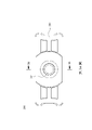
請參照第2G圖至第2J圖,其中第2G圖繪示依照第2A圖第二實施例中鏡筒230的參數示意圖,第2H圖繪示依照第2A圖第二實施例中鏡筒230的立體圖,第2I圖繪示依照第2A圖第二實施例中鏡筒230的另一立體圖,第2J圖繪示依照第2A圖第二實施例中鏡筒230的剖面圖。由第2G圖至第2J圖可知,鏡筒230包含一筒狀部231與一底座部232,其中筒狀部231具有一第一內表面231a用以定義一第一內部空間231b,且成像透鏡組設置於第一內部空間231b;底座部232具有一第二內表面232a用以定義一第二內部空間232b,且底座部232自筒狀部231沿光軸X延伸並與基板210實體接觸,使筒狀部231與一成像面維持一固定距離。具體而言,鏡筒230可為無螺牙結構,並可通過底座部232的底面直接與基板210連接固定。再者,筒狀部231與底座部232為一體成型,藉以減少成像鏡頭模組200的組裝程序,以提升生產效率,並可避免習知技術的成像鏡頭與底座部232安裝時產生的歪斜誤差。Please refer to FIG. 2G to FIG. 2J, wherein FIG. 2G shows a schematic diagram of the parameters of the
進一步來說,鏡筒230的筒狀部231包含二第二縮減面252,其中第二縮減面252對稱於光軸X設置,第二縮減面252設置於第一內表面231a對應第一縮減面251的位置,第二縮減面252自第一內表面231a朝靠近光軸X的方向縮減,使第一內表面231a沿光軸X觀察的輪廓呈非圓形。第二實施例中,第二縮減面252可為曲面。Further, the
進一步來說,透過透鏡224的第一縮減面251與筒狀部231的第二縮減面252,可使成像鏡頭模組200在垂直光軸X的方向上的尺寸縮小,藉以實現成像鏡頭模組200微小化,換言之,於有限的空間中仍可安裝成像鏡頭模組200。Furthermore, through the first reducing
由第2A圖可知,透鏡221、222、223、224中最像側的一透鏡(即透鏡224)包含第一縮減面251。藉此,有利於實現成像鏡頭模組200的微小化。具體而言,由最大直徑的透鏡開始設置第一縮減面251。It can be seen from FIG. 2A that the most image-side lens among the
再者,由最像側的透鏡(即透鏡224)往物側的相鄰至少二透鏡包含第一縮減面251(以透鏡224的標示為例)。藉此,可應用於窄邊框的筆記型電腦,但並不以此應用為限。Furthermore, at least two lenses adjacent to the object side from the lens on the most image side (that is, the lens 224 ) include the first reducing surface 251 (take the label of the
進一步來說,最物側至最像側的每一透鏡221、222、223、224分別包含第一縮減面251(以透鏡224的標示為例),且遮光元件241、242、243及固定元件244皆包含縮減部。藉此,可在垂直光軸X的方向上進一步縮小成像鏡頭模組200的尺寸。具體而言,於最物側的透鏡(即透鏡221)至最像側的透鏡(即透鏡224)皆包含第一縮減面251(以透鏡224的標示為例)的情況下,同時要維持成像鏡頭模組200的成像品質,並需要高生產良率。Further, each
由第2C圖可知,第一縮減面251與第二縮減面252間隔設置,其中一空氣間隙G設置於第一縮減面251與第二縮減面252之間。藉此,可避免透鏡221、222、223、224過度定位造成組裝誤差。It can be seen from FIG. 2C that the first reducing
由第2D圖與第2F圖可知,透鏡221、222、223、224分別更包含一邊緣部224b(以透鏡224的標示為例)與一光學有效部224c(以透鏡224的標示為例),邊緣部224b較光學有效部224c遠離光軸X,光學有效部224c具有光線屈折力,第一縮減面251使光學有效部224c沿光軸X觀察的輪廓呈非圓形。It can be seen from FIG. 2D and FIG. 2F that the
底座部232更包含二第三縮減面253,其中第三縮減面253對稱於光軸X設置,第三縮減面253設置於第二內表面232a,且第三縮減面253自第二內表面232a朝靠近光軸X的方向縮減,使底座部232沿光軸X觀察的輪廓呈非圓形。藉此,可使鏡筒230在垂直光軸X的方向上進一步壓縮尺寸,減少安裝於基板210所需的空間。第二實施例中,第三縮減面253可為平面與曲面的組合。The
底座部232更包含一消光層,設置於第二內表面232a。藉此,可避免非成像光線在底座部232的內部發生反射,影響成像品質。具體而言,消光層可為抗反射結構,或者可經過噴砂處理或鍍膜處理,但不以此為限。The
由第2A圖與第2C圖可知,底座部232包含一紅外濾光片234,其中紅外濾光片234設置於第二內部空間232b。藉此,可濾除紅外光以提升成像品質。It can be seen from FIG. 2A and FIG. 2C that the
由第2H圖與第2I圖可知,鏡筒230更包含二第四縮減面254,其中第四縮減面254對稱於光軸X設置,第四縮減面254設置於鏡筒230的一外表面,第四縮減面254自鏡筒230的外表面朝靠近光軸X的方向縮減,且第四縮減面254由筒狀部231沿光軸X延伸至底座部232,使鏡筒230沿光軸X觀察的輪廓呈非圓形。第二實施例中,第四縮減面254可為平面與曲面的組合。必須說明的是,各縮減面(即第二縮減面252、第三縮減面253、第四縮減面254)上的圖案僅用於示意縮減面範圍,不構成各縮減面的結構的一部分。It can be seen from FIG. 2H and FIG. 2I that the
透鏡中最像側的透鏡(即透鏡224)透過一點膠方式與鏡筒230連接。可透過點膠方式固定透鏡提升生產效率,並增加組裝穩固性。具體而言,點膠方式的膠水設置於邊緣部224b與鏡筒230連接,且膠水可為黑色膠水,藉以降低非成像光線的反射率。再者,鏡筒230的內表面可以設置點膠結構,並可透過影像辨識判斷填膠情況。The most image-side lens among the lenses (that is, the lens 224 ) is connected to the
由第2A圖、第2B圖、第2D圖、第2H圖、第2I圖及第2J圖可知,底座部232包含一逃氣口235,其中逃氣口235連通第二內部空間232b與鏡筒230的一外部空間,逃氣口235沿平行光軸X的方向延伸,且逃氣口235由筒狀部231往底座部232漸縮。透過逃氣口235連通鏡筒230的第二內部空間232b與外部空間以平衡壓力,避免組裝過程中成像鏡頭模組200因內部氣壓導致成像鏡頭模組200的偏移。As can be seen from Figures 2A, 2B, 2D, 2H, 2I and 2J, the
由第2A圖可知,成像鏡頭模組200更包含一光路轉折元件260,其中光路轉折元件260用以導引一光線至成像鏡頭。具體來說,光路轉折元件260可為稜鏡或反射鏡,並可設置於成像鏡頭與入光口之間,但並不以此為限。It can be seen from FIG. 2A that the
由第2C圖、第2D圖及第2G圖可知,透鏡224的第一縮減面251之間具有一最短間距,筒狀部231的第二縮減面252之間具有一最短間距,光軸X垂直通過第一縮減面251之間的最短間距與第二縮減面252之間的最短間距,第一縮減面251之間的最短間距為L1,第二縮減面252之間的最短間距為L2;透鏡224的一直徑為φ;鏡筒230的底座部232沿光軸X的一高度為H1,鏡筒230整體沿光軸X的一高度為H;鏡筒230的第四縮減面254之間於最像側具有一第一最短寬度,鏡筒230的第四縮減面254之間於最物側具有一第二最短寬度,光軸X垂直通過第一最短寬度與第二最短寬度,第一最短寬度與第二最短寬度之間具有一寬度差,第一最短寬度為W1,第二最短寬度為W2,寬度差為ΔW;各透鏡221、222、223、224的光學有效部224c(以透鏡224的標示為主)的一直徑為φeff,所述參數滿足下列表二條件。
第二實施例中,第一縮減面251之間的最短間距與透鏡224,其滿足下列條件:L1 < φeff。In the second embodiment, the shortest distance between the first reducing
<第三實施例><Third embodiment>
請參照第3A圖與第3B圖,其中第3A圖繪示依照本揭示內容第三實施例中成像鏡頭模組300的示意圖,第3B圖繪示依照第3A圖第三實施例中成像鏡頭模組300沿剖線3B-3B的剖面圖。由第3A圖與第3B圖可知,成像鏡頭模組300包含一基板(圖未繪示)與一成像鏡頭(圖未標示),其中基板包含一感光元件(圖未繪示),一光軸(圖未標示)通過成像鏡頭,且成像鏡頭包含一成像透鏡組(圖未標示)與一鏡筒330。具體而言,成像鏡頭模組300可為筆記型電腦的成像鏡頭模組或行動裝置的成像鏡頭模組,但不以此為限。Please refer to FIG. 3A and FIG. 3B, wherein FIG. 3A shows a schematic diagram of the
由第3B圖可知,成像透鏡組包含至少一透鏡,其中成像透鏡組的透鏡的數量可為複數,且成像透鏡組可更包含遮光元件與固定元件。第三實施例中,成像透鏡組由物側至像側依序包含透鏡321、遮光元件341、透鏡322、遮光元件342、透鏡323、遮光元件343、透鏡324及固定元件344。必須說明的是,透鏡及各光學元件的數量、結構、面形等光學特徵可依照不同成像需求配置,並不以此為限。It can be seen from FIG. 3B that the imaging lens group includes at least one lens, wherein the number of lenses in the imaging lens group can be plural, and the imaging lens group can further include a light shielding element and a fixing element. In the third embodiment, the imaging lens group includes a
透鏡324包含二第一縮減面351,其中第一縮減面351對稱於光軸設置,且第一縮減面351自透鏡324的一外緣面(圖未標示)朝靠近光軸的方向縮減,使透鏡324沿光軸觀察的輪廓呈非圓形。第三實施例中,第一縮減面351可為平面。The
請參照第3C圖至第3F圖,其中第3C圖繪示依照第3A圖第三實施例中鏡筒330的參數示意圖,第3D圖繪示依照第3A圖第三實施例中鏡筒330的立體圖,第3E圖繪示依照第3D圖第三實施例中鏡筒330的剖切面,第3F圖繪示依照第3A圖第三實施例中鏡筒330的另一立體圖。由第3C圖至第3F圖可知,鏡筒330包含一筒狀部331與一底座部332,其中筒狀部331具有一第一內表面331a用以定義一第一內部空間331b,且成像透鏡組設置於第一內部空間331b;底座部332具有一第二內表面332a用以定義一第二內部空間332b,且底座部332自筒狀部331沿光軸延伸並與基板實體接觸,使筒狀部331與一成像面維持一固定距離。具體而言,鏡筒330可為無螺牙結構,並可通過底座部332的底面直接與基板連接固定。再者,筒狀部331與底座部332為一體成型,藉以減少成像鏡頭模組300的組裝程序,以提升生產效率,並可避免習知技術的成像鏡頭與底座部安裝時產生的歪斜誤差。Please refer to FIG. 3C to FIG. 3F, wherein FIG. 3C shows a schematic diagram of the parameters of the
進一步來說,鏡筒330的筒狀部331包含二第二縮減面352,其中第二縮減面352對稱於光軸設置,第二縮減面352設置於第一內表面331a對應第一縮減面351的位置,第二縮減面352自第一內表面331a朝靠近光軸的方向縮減,使第一內表面331a沿光軸觀察的輪廓呈非圓形。第三實施例中,第二縮減面352可為平面。Further, the
進一步來說,透過透鏡324的第一縮減面351與筒狀部331的第二縮減面352,可使成像鏡頭模組300在垂直光軸的方向上的尺寸縮小,藉以實現成像鏡頭模組300微小化,換言之,於有限的空間中仍可安裝成像鏡頭模組300。Further, through the first reducing
由第3B圖可知,第一縮減面351與第二縮減面352間隔設置,其中一空氣間隙G設置於第一縮減面351與第二縮減面352之間。藉此,可避免透鏡321、322、323、324過度定位造成組裝誤差。It can be seen from FIG. 3B that the first reducing
底座部332更包含二第三縮減面353,其中第三縮減面353對稱於光軸設置,第三縮減面353設置於第二內表面332a,且第三縮減面353自第二內表面332a朝靠近光軸的方向縮減,使底座部332沿光軸觀察的輪廓呈非圓形。藉此,可使鏡筒330在垂直光軸的方向上進一步壓縮尺寸,減少安裝於基板所需的空間。第三實施例中,第三縮減面353可為平面。The
底座部332更包含一消光層,設置於第二內表面332a。藉此,可避免非成像光線在底座部332的內部發生反射,影響成像品質。具體而言,消光層可為抗反射結構,或者可經過噴砂處理或鍍膜處理,但不以此為限。The
由第3B圖可知,底座部332包含一紅外濾光片334,其中紅外濾光片334設置於第二內部空間332b。藉此,可濾除紅外光以提升成像品質。It can be seen from FIG. 3B that the
由第3D圖至第3F圖可知,鏡筒330更包含二第四縮減面354,其中第四縮減面354對稱於光軸設置,第四縮減面354設置於鏡筒330的一外表面,第四縮減面354自鏡筒330的外表面朝靠近光軸的方向縮減,且第四縮減面354由筒狀部331沿光軸延伸至底座部332,使鏡筒330沿光軸觀察的輪廓呈非圓形。第三實施例中,第四縮減面354可為平面。It can be seen from Figures 3D to 3F that the
透鏡中最像側的透鏡(即透鏡324)透過一點膠方式與鏡筒330連接。可透過點膠方式固定透鏡提升生產效率,並增加組裝穩固性。具體而言,點膠方式的膠水設置於邊緣部(圖未標示)與鏡筒330連接,且膠水可為黑色膠水,藉以降低非成像光線的反射率。再者,鏡筒330的內表面可以設置點膠結構,並可透過影像辨識判斷填膠情況。The lens on the most image side among the lenses (that is, the lens 324 ) is connected to the
由第3B圖與第3C圖可知,鏡筒330的底座部332沿光軸的一高度為H1,鏡筒330整體沿光軸的一高度為H;鏡筒330的第四縮減面354之間於最像側具有一第一最短寬度,鏡筒330的第四縮減面354之間於最物側具有一第二最短寬度,光軸垂直通過第一最短寬度與第二最短寬度,第一最短寬度與第二最短寬度之間具有一寬度差,第一最短寬度為W1,第二最短寬度為W2,寬度差為ΔW,所述參數滿足下列表三條件。
另外,第三實施例與第一實施例其餘的元件之結構及配置關係皆相同,在此將不另贅述。In addition, the third embodiment is the same as the first embodiment in terms of structure and arrangement of other components, and will not be repeated here.
<第四實施例><Fourth embodiment>
請參照第4圖,其繪示依照本揭示內容第四實施例中電子裝置40的示意圖。由第4圖可知,電子裝置40為一筆記型電腦,且包含一面板螢幕41與一成像鏡頭模組42,其中面板螢幕41所佔電子裝置40的一屏佔比為92%以上。再者,面板螢幕41所佔電子裝置40的屏佔比可為95%以上。具體而言,成像鏡頭模組42可為前述第一實施例至第三實施例的成像鏡頭模組,且成像鏡頭模組42設置於面板螢幕41的一邊框43,但並不以此為限。Please refer to FIG. 4 , which shows a schematic diagram of an
進一步來說,使用者透過電子裝置40的面板螢幕41進入拍攝模式。此時成像鏡頭模組42匯集成像光線在電子裝置40的一電子感光元件(圖未繪示)上,並輸出有關影像的電子訊號至成像訊號處理元件(Image Signal Processor,ISP)(圖未繪示)。Furthermore, the user enters the shooting mode through the
再者,成像鏡頭模組與電子感光元件可設置在一軟性電路板(Flexible Printed Circuitboard,FPC)(圖未繪示)上,並透過一連接器(圖未繪示)電性連接成像訊號處理元件等相關元件以執行拍攝流程。當前的電子裝置具有輕薄的趨勢,將成像鏡頭模組與相關元件配置於軟性電路板上,再利用連接器將電路彙整至電子裝置的主板,可滿足電子裝置內部有限空間的機構設計及電路佈局需求並獲得更大的裕度。Moreover, the imaging lens module and the electronic photosensitive element can be arranged on a flexible printed circuit board (Flexible Printed Circuitboard, FPC) (not shown in the figure), and are electrically connected to the imaging signal processing through a connector (not shown in the figure). Components and other related components to execute the shooting process. The current electronic devices have a trend of thinner and thinner. The imaging lens module and related components are arranged on the flexible circuit board, and then the circuit is integrated to the main board of the electronic device by using a connector, which can meet the mechanism design and circuit layout of the limited space inside the electronic device. demand and gain greater margins.
此外,電子裝置40可更包含但不限於顯示單元(Display)、控制單元(Control Unit)、儲存單元(Storage Unit)、暫儲存單元(RAM)、唯讀儲存單元(ROM)或其組合。In addition, the
雖然本發明已以實施例揭露如上,然其並非用以限定本發明,任何所屬技術領域中具有通常知識者,在不脫離本發明的精神和範圍內,當可作些許的更動與潤飾,故本發明的保護範圍當視後附的申請專利範圍所界定者為準。Although the present invention has been disclosed above with the embodiments, it is not intended to limit the present invention. Anyone with ordinary knowledge in the technical field may make some changes and modifications without departing from the spirit and scope of the present invention. The scope of protection of the present invention should be defined by the scope of the appended patent application.
100,200,300,42:成像鏡頭模組
110,210:基板
111,211:感光元件
121,122,123,124,221,222,223,224,321,322,323,324:透鏡
124a,224a:外緣面
124b,224b:邊緣部
124c,224c:光學有效部
130,230,330,50:鏡筒
131,231,331,51:筒狀部
131a,231a,331a:第一內表面
131b,231b,331b:第一內部空間
132,232,332,52:底座部
132a,232a,332a:第二內表面
132b,232b,332b:第二內部空間
134,234,334:紅外濾光片
141,142,143,241,242,243,341,342,343:遮光元件
144,244,344:固定元件
151,251,351:第一縮減面
152,252,352:第二縮減面
153,253,353:第三縮減面
154,254,354:第四縮減面
235:逃氣口
260:光路轉折元件
40:電子裝置
41:面板螢幕
43:邊框
X:光軸
G:空氣間隙
L1:第一縮減面之間的最短間距
L2:第二縮減面之間的最短間距
φ:透鏡的直徑
H1:鏡筒的底座部沿光軸的高度
H:鏡筒整體沿光軸的高度
W1:第一最短寬度
W2:第二最短寬度
ΔW:寬度差
φeff:各透鏡的光學有效部的直徑
100,200,300,42: imaging lens module
110,210: Substrate
111,211: photosensitive element
121,122,123,124,221,222,223,224,321,322,323,324:
第1A圖繪示依照本揭示內容第一實施例中成像鏡頭模組的分解圖;
第1B圖繪示依照第1A圖第一實施例中成像鏡頭模組的示意圖;
第1C圖繪示依照第1B圖第一實施例中成像鏡頭模組沿剖線1C-1C的剖面圖;
第1D圖繪示依照第1A圖第一實施例中成像鏡頭模組的像側示意圖;
第1E圖繪示依照第1A圖第一實施例中透鏡的側視圖;
第1F圖繪示依照第1A圖第一實施例中透鏡的示意圖;
第1G圖繪示依照第1A圖第一實施例中鏡筒的參數示意圖;
第1H圖繪示依照第1A圖第一實施例中鏡筒的立體圖;
第1I圖繪示依照第1A圖第一實施例中鏡筒的另一立體圖;
第1J圖繪示依照第1A圖第一實施例中鏡筒的剖面圖;
第2A圖繪示依照本揭示內容第二實施例中成像鏡頭模組的分解圖;
第2B圖繪示依照第2A圖第二實施例中成像鏡頭模組的示意圖;
第2C圖繪示依照第2B圖第二實施例中成像鏡頭模組沿剖線2C-2C的剖面圖;
第2D圖繪示依照第2A圖第二實施例中成像鏡頭模組的像側示意圖;
第2E圖繪示依照第2A圖第二實施例中透鏡的側視圖;
第2F圖繪示依照第2A圖第二實施例中透鏡的示意圖;
第2G圖繪示依照第2A圖第二實施例中鏡筒的參數示意圖;
第2H圖繪示依照第2A圖第二實施例中鏡筒的立體圖;
第2I圖繪示依照第2A圖第二實施例中鏡筒的另一立體圖;
第2J圖繪示依照第2A圖第二實施例中鏡筒的剖面圖;
第3A圖繪示依照本揭示內容第三實施例中成像鏡頭模組的示意圖;
第3B圖繪示依照第3A圖第三實施例中成像鏡頭模組沿剖線3B-3B的剖面圖;
第3C圖繪示依照第3A圖第三實施例中鏡筒的參數示意圖;
第3D圖繪示依照第3A圖第三實施例中鏡筒的立體圖;
第3E圖繪示依照第3D圖第三實施例中鏡筒的剖切面;
第3F圖繪示依照第3A圖第三實施例中鏡筒的另一立體圖;
第4圖繪示依照本揭示內容第四實施例中電子裝置的示意圖;
第5A圖繪示依照現有技術中鏡筒的示意圖;以及
第5B圖繪示依照第5A圖現有技術中鏡筒的另一示意圖。
FIG. 1A shows an exploded view of an imaging lens module according to a first embodiment of the present disclosure;
FIG. 1B shows a schematic diagram of the imaging lens module in the first embodiment according to FIG. 1A;
FIG. 1C shows a cross-sectional view of the imaging lens module along the
100:成像鏡頭模組
110:基板
111:感光元件
121,122,123,124:透鏡
130:鏡筒
134:紅外濾光片
141,142,143:遮光元件
144:固定元件
X:光軸
100: Imaging lens module
110: Substrate
111: photosensitive element
121,122,123,124: lens
130: lens barrel
134:
Claims (20)
Applications Claiming Priority (2)
| Application Number | Priority Date | Filing Date | Title |
|---|---|---|---|
| US202163211037P | 2021-06-16 | 2021-06-16 | |
| US63/211,037 | 2021-06-16 |
Publications (2)
| Publication Number | Publication Date |
|---|---|
| TW202300969A TW202300969A (en) | 2023-01-01 |
| TWI793799B true TWI793799B (en) | 2023-02-21 |
Family
ID=81762186
Family Applications (1)
| Application Number | Title | Priority Date | Filing Date |
|---|---|---|---|
| TW110138063A TWI793799B (en) | 2021-06-16 | 2021-10-14 | Imaging lens assembly module and electronic device |
Country Status (3)
| Country | Link |
|---|---|
| US (1) | US20220404583A1 (en) |
| CN (2) | CN216670378U (en) |
| TW (1) | TWI793799B (en) |
Citations (2)
| Publication number | Priority date | Publication date | Assignee | Title |
|---|---|---|---|---|
| TW201740149A (en) * | 2016-05-09 | 2017-11-16 | 大立光電股份有限公司 | Imaging lens assembly and electronic device |
| TW201925842A (en) * | 2017-12-01 | 2019-07-01 | 大陸商信泰光學(深圳)有限公司 | Lens module |
-
2021
- 2021-10-14 TW TW110138063A patent/TWI793799B/en active
-
2022
- 2022-01-19 CN CN202220134323.XU patent/CN216670378U/en active Active
- 2022-01-19 CN CN202210057952.1A patent/CN115480363A/en active Pending
- 2022-05-20 US US17/749,213 patent/US20220404583A1/en active Pending
Patent Citations (3)
| Publication number | Priority date | Publication date | Assignee | Title |
|---|---|---|---|---|
| TW201740149A (en) * | 2016-05-09 | 2017-11-16 | 大立光電股份有限公司 | Imaging lens assembly and electronic device |
| US20190155001A1 (en) * | 2016-05-09 | 2019-05-23 | Largan Precision Co., Ltd. | Imaging lens assembly and electronic device |
| TW201925842A (en) * | 2017-12-01 | 2019-07-01 | 大陸商信泰光學(深圳)有限公司 | Lens module |
Also Published As
| Publication number | Publication date |
|---|---|
| US20220404583A1 (en) | 2022-12-22 |
| TW202300969A (en) | 2023-01-01 |
| CN115480363A (en) | 2022-12-16 |
| CN216670378U (en) | 2022-06-03 |
Similar Documents
| Publication | Publication Date | Title |
|---|---|---|
| TWI623787B (en) | Imaging lens set with plastic lens element, imaging lens module and electronic device | |
| US11579341B2 (en) | Lens, camera module and manufacturing method thereof | |
| TWI657281B (en) | Imaging lens set with plastic lens element, imaging lens module and electronic device | |
| TWI672538B (en) | Camera module and electronic device | |
| TWI701473B (en) | Imaging lens assembly module, camera module and electronic device | |
| TW201908793A (en) | Imaging lens, camera module and electronic device | |
| TWI672537B (en) | Plastic lens assembly, imaging lens module and electronic device | |
| TWI682611B (en) | Photographing module with leaf spring and electronic device including same module | |
| TWI671548B (en) | Imaging lens assembly, camera module and electronic device | |
| TW201910843A (en) | Imaging lens assembly, camera module and electronic device | |
| KR20190066522A (en) | Lens module and mobile device including the smae | |
| US20220163750A1 (en) | Lens structure and method for assembling same, and camera module | |
| TWM584902U (en) | Camera device | |
| TWI692400B (en) | Optical lens assembly and electronic device | |
| TWI793799B (en) | Imaging lens assembly module and electronic device | |
| TW202014752A (en) | Imaging lens assembly with metal retainer, camera module including same assembly and electronic device including same module | |
| TWI769815B (en) | Plastic light-folding element, imaging lens assembly module and electronic device | |
| TWI777542B (en) | Imaging lens assembly and electronic device | |
| TWI691782B (en) | Plastic lens barrel, imaging lens module and electronic device | |
| US20240069302A1 (en) | Lens, lens module, and electronic device | |
| TWI784743B (en) | Camera module and electronic device | |
| EP4102263A1 (en) | Camera module and electronic device | |
| TWI829423B (en) | Imaging lens assembly and electronic device | |
| TWI784676B (en) | Plastic light-folding element, imaging lens assembly module and electronic device | |
| WO2023061138A1 (en) | Electronic device |