TWI764330B - Elevator tractor - Google Patents
Elevator tractorInfo
- Publication number
- TWI764330B TWI764330B TW109136285A TW109136285A TWI764330B TW I764330 B TWI764330 B TW I764330B TW 109136285 A TW109136285 A TW 109136285A TW 109136285 A TW109136285 A TW 109136285A TW I764330 B TWI764330 B TW I764330B
- Authority
- TW
- Taiwan
- Prior art keywords
- output shaft
- base
- brake
- rotary encoder
- holes
- Prior art date
Links
Images


Abstract
Description
本發明係有關於一種電梯曳引機結構,尤指一種可避免曳引機之出力軸產生偏心問題,並可提高曳引機使用壽命及維修方便性等效能之結構。 The present invention relates to an elevator traction machine structure, especially a structure that can avoid the eccentric problem of the output shaft of the traction machine, and can improve the service life of the traction machine and the efficiency of maintenance.
按,現有曳引機係主要於機座之馬達容腔內設有對應設立之定子及轉子,並於轉子中心組設有一出力軸,又於出力軸前端設有一曳引輪,另於該機座後側位於該出力軸後端處組設有一旋轉編碼器,且於機座前側設有一鋼索防脫桿。藉此,當啟動該曳引機運作時,係供電予定子以與轉子間產生旋轉磁場,以帶動轉子之出力軸轉動,進而驅使出力軸相接之曳引輪轉動,隨之帶動曳引輪上之鋼索牽引電梯車廂或配重塊等負載升降作動,當出力軸轉動時,旋轉編碼器係會同步偵測出力軸轉速,並轉換為電梯車廂位移的即時位置,另當鋼索欲跳脫時藉由鋼索防脫桿以將鋼索彈回復位。 Press, the existing traction machine is mainly equipped with a corresponding stator and a rotor in the motor cavity of the machine base, and a power output shaft is set in the center of the rotor, and a traction sheave is set at the front end of the output shaft. A rotary encoder is assembled on the rear side at the rear end of the output shaft, and a steel cable anti-dropping rod is arranged on the front side of the machine base. Therefore, when the hoisting machine is started to operate, power is supplied to the stator to generate a rotating magnetic field between the stator and the rotor, so as to drive the output shaft of the rotor to rotate, and then drive the traction sheave connected to the output shaft to rotate, thereby driving the traction sheave on the traction sheave. When the wire rope pulls the elevator car or the counterweight and other loads up and down, when the output shaft rotates, the rotary encoder system will synchronously detect the output shaft speed and convert it into the real-time position of the elevator car displacement. Wire rope anti-slip bar to bounce the wire back into place.
然,現有曳引機由於其出力軸前端係呈懸空缺乏支撐,當曳引機作動時,因車廂重量、平衡配重、人員載重及反作用力等產生的徑向負載,會透過曳引輪作用於出力軸上,而使出力軸極易因該徑向負載重壓產生偏心問題,以致造成曳引機提早損壞缺失,又現有曳引機其旋轉編碼器的裝設係於機座後側,以致機座後側與電梯井牆壁之距離無法有效減縮,於此,不僅佔空間 安裝不便,且當旋轉編碼器故障須維修時,須將整個曳引機拆下,再將曳引機前後翻轉後,才有辦法進行旋轉編碼器的維修更換,而造成旋轉編碼器維修更換上極大不便性,又現有曳引機於鋼索欲跳脫時係利用鋼索防脫桿將鋼索彈回限位,但鋼索防脫桿之組設,需由馬達外殼再外接架設,於工序上仍有改善空間。另當停、斷電等造成電梯車廂停止運作時,現有曳引機雖可經由盤車以手動方式將電梯車廂作動至指定樓層,以對電梯車廂內的人員或物品提供救援,然安裝盤車上須佔用一定空間及造成機構設計上的複雜性。 However, the front end of the output shaft of the existing traction machine is suspended in the air and lacks support. When the traction machine operates, the radial load generated by the weight of the carriage, the balance weight, the personnel load and the reaction force will act on the traction sheave through the traction sheave. On the output shaft, the output shaft is easily eccentric due to the radial load and heavy pressure, resulting in premature damage and loss of the traction machine. In addition, the rotary encoder of the existing traction machine is installed on the back side of the machine base, so that The distance between the rear side of the machine base and the wall of the elevator shaft cannot be effectively reduced, which not only takes up space Installation is inconvenient, and when the rotary encoder fails and needs to be repaired, the entire traction machine must be removed, and then the traction machine is turned back and forth before the rotary encoder can be repaired and replaced, resulting in the maintenance and replacement of the rotary encoder. It is very inconvenient, and the existing traction machine uses the wire rope anti-dropping rod to bounce the wire back to the limit when the wire rope is about to jump off. room for improvement. In addition, when the elevator car stops running due to stopping, power failure, etc., although the existing traction machine can manually move the elevator car to the designated floor through the cranking machine to provide rescue for the people or objects in the elevator car, the cranking machine is installed. It takes up a certain space and causes complexity in the design of the mechanism.
緣是,本發明人有鑑於現有曳引機於使用實施上仍有上述缺失,乃藉其多年於相關領域的製造及設計經驗和知識的輔佐,並經多方巧思,研創出本發明。 The reason is that the inventors of the present invention have developed the present invention with the help of years of experience and knowledge in manufacturing and design in the related fields in view of the above-mentioned deficiencies in the use and implementation of the existing traction machines.
本發明係有關於一種電梯曳引機結構,其一目的在於曳引機之出力軸前、後端分別穿接於機座及固定座之軸承,以解決曳引機作動時,出力軸會因徑向負載產生偏心問題;其二目的在於將旋轉編碼器組設於曳引機前側,以解決旋轉編碼器不易維修更換問題;其三目的在於曳引輪上方蓋設有一鋼索防脫板,避免曳引輪上之鋼索發生跳脫情形,增強電梯裝置安全性;其四目的在於使定子由一長條形矽鋼片捲繞成環圈體,以縮小定子體積,並減少定子製造工時與成本,及增加定子各繞線槽內線圈截面積,以提高單位面積電流量及轉矩與發電效率。其五目的在於其出力軸相對旋轉編碼器的另端鎖接有一盤車轉接器,以利與盤車進行組裝,藉由手動檢測該出力軸是否有異音干涉或生銹等情況,或當斷電或故障停車時,便利對關在電梯車廂內的人員或物品等提供救援者。 The present invention relates to an elevator traction machine structure, and one of its objectives is to connect the front and rear ends of the output shaft of the traction machine to the bearings of the machine base and the fixed seat respectively, so as to solve the problem that the output shaft will be Radial load causes eccentricity problem; the second purpose is to set the rotary encoder on the front side of the traction machine to solve the problem that the rotary encoder is not easy to maintain and replace; the third purpose is that the upper cover of the traction sheave is provided with a steel cable anti-drop plate to avoid traction The wire rope on the pulley is tripped, which enhances the safety of the elevator installation; its four purposes are to make the stator wound into a ring body from a long strip of silicon steel sheet, so as to reduce the volume of the stator and reduce the man-hour and cost of manufacturing the stator, and Increase the cross-sectional area of the coils in each winding slot of the stator to improve the current per unit area, torque and power generation efficiency. The fifth purpose is to lock a crank adapter to the other end of the output shaft relative to the rotary encoder, so as to facilitate the assembly with the crank, and manually detect whether the output shaft has abnormal noise interference or rust, or In the event of a power failure or failure to stop, it is convenient for rescuers to provide rescuers to people or objects locked in the elevator car.
為了達到上述實施目的,本發明人乃研擬如下電梯曳引機結構,係主要設有一曳引機之機座,並於該機座成型有一馬達容腔,且於該馬達容腔內設有相對應設立之一定子及一轉子,該定子係由一長條形矽鋼片一體捲繞形成一環圈體,又於該轉子中心組設有一出力軸,並於該出力軸上組接有一曳引輪,另於該機座設有一第一組孔,且使該出力軸後端穿設於該機座之第一組孔,另設有一固定座,乃使該固定座位於該機座前側,並與該機座前側相連結,又於該固定座設有一第二組孔,且使該出力軸前端穿設於該固定座之第二組孔,另使該固定座與該機座間形成有一容置區間,且於該容置區間的左、右兩側各形成一敞開之開口,並使該曳引輪位於該容置區間,而使該曳引輪設置於該出力軸的中段位置處,復設有一盤車轉接器,且使該盤車轉接器組接於該出力軸一端中心處。 In order to achieve the above-mentioned implementation purpose, the present inventor has developed the following elevator traction machine structure, which is mainly provided with a chassis of the traction machine, and a motor cavity is formed in the chassis, and a motor cavity is provided in the motor cavity. Correspondingly set up a stator and a rotor. The stator is integrally wound by a long strip of silicon steel to form a ring body, and an output shaft is arranged in the center of the rotor, and a traction wheel is assembled on the output shaft. , in addition, a first group of holes is arranged in the base, and the rear end of the output shaft passes through the first group of holes in the base, and a fixing seat is arranged so that the fixing seat is located on the front side of the base, and It is connected with the front side of the base, and a second group of holes is arranged on the fixed base, and the front end of the output shaft is passed through the second set of holes in the fixed base, and a space is formed between the fixed base and the base. The accommodating section is formed, and an opening is formed on the left and right sides of the accommodating section, and the traction sheave is located in the accommodating section, and the traction sheave is set at the middle position of the output shaft. There is a cranking adapter, and the cranking adapter is assembled at the center of one end of the output shaft.
如上所述電梯曳引機結構,其中,該機座之第一組孔係組設有至少一第一軸承,另該固定座之第二組孔係組設有至少一第二軸承,又使該出力軸後端穿設於該機座其第一組孔中之第一軸承,另使該出力軸前端穿設於該固定座其第二組孔中之第二軸承。 The elevator traction machine structure as described above, wherein the first group of holes of the machine base is provided with at least one first bearing, and the second group of holes of the fixed seat is provided with at least one second bearing, so that the The rear end of the output shaft passes through the first bearing in the first set of holes in the base, and the front end of the output shaft passes through the second bearing in the second set of holes in the fixing base.
如上所述電梯曳引機結構,其中,該電梯曳引機結構係進一步包含有一旋轉編碼器,該旋轉編碼器係位於該盤車轉接器的相對另側,乃使該旋轉編碼器選擇性地組設於該固定座的前側處,而與該出力軸的前端位置相對應,另該盤車轉接器係相對組接於該出力軸的後端中心處;或使該旋轉編碼器選擇性地組設於該機座的後側處,而與該出力軸的後端位置相對應,另該盤車轉接器係相對組接於該出力軸的前端中心處。 The elevator traction machine structure as described above, wherein, the elevator traction machine structure further includes a rotary encoder, and the rotary encoder is located on the opposite side of the barring adapter, so that the rotary encoder can be selectively It is assembled at the front side of the fixed seat and corresponds to the front end position of the output shaft, and the cranking adapter is relatively assembled at the center of the rear end of the output shaft; or the rotary encoder is selected The crank adaptor is assembled at the rear side of the machine base, corresponding to the rear end of the output shaft, and the crank adapter is relatively assembled at the center of the front end of the output shaft.
如上所述電梯曳引機結構,其中,該旋轉編碼器係設有一檢出梢,又於該出力軸其前端及後端的中心處各設有一插槽,另設有一護蓋,該護蓋係於其內面成型有一嵌槽,並於該護蓋周側設有數鎖孔;又該盤車轉接器係於一 端設有一鎖接段,另設有一封蓋,該封蓋係於中心處設有一穿孔,而於該封蓋周側設有數鎖孔;乃使該旋轉編碼器選擇性地設置於該固定座其第二組孔處,而使其檢出梢對應插設於該出力軸前端之插槽定位,又使該護蓋位於該固定座前側,以將該旋轉編碼器覆蓋於內,且使該旋轉編碼器嵌設於該護蓋內面之嵌槽定位,另於該護蓋其各鎖孔分別穿設有一鎖固件,以與該固定座鎖接結合,又該盤車轉接器之鎖接段係對應鎖固於該出力軸後端之插槽中,另使該封蓋位於該機座後側,以將該機座其第一組孔後側覆蓋於內,又於該封蓋其各鎖孔分別穿設有一鎖固件,以與該機座鎖接結合,且使該盤車轉接器相對其鎖接段之另端位於該封蓋之穿孔外;或使該旋轉編碼器選擇性地設置於該機座其第一組孔處,而使其檢出梢對應插設於該出力軸後端之插槽定位,又使該護蓋位於該機座後側,以將該旋轉編碼器覆蓋於內,並使該旋轉編碼器嵌設於該護蓋內面之嵌槽定位,另於該護蓋其各鎖孔分別穿設有一鎖固件,以與該機座鎖接結合,而該盤車轉接器之鎖接段則對應鎖固於該出力軸前端之插槽中,另使該封蓋位於該固定座前側,以將該固定座其第二組孔前側覆蓋於內,又於該封蓋其各鎖孔分別穿設有一鎖固件,以與該固定座鎖接結合,且使該盤車轉接器相對其鎖接段之另端位於該封蓋之穿孔外。 The elevator traction machine structure as described above, wherein, the rotary encoder is provided with a detection pin, and a slot is respectively provided at the center of the front end and the rear end of the output shaft, and a protective cover is provided, and the protective cover is An insert groove is formed on its inner surface, and a number of lock holes are arranged on the peripheral side of the protective cover; and the cranking adapter is fastened to a The end is provided with a locking section, and the other is provided with a cover, the cover is provided with a hole in the center, and a number of lock holes are arranged on the peripheral side of the cover; so that the rotary encoder can be selectively arranged on the fixed seat At the second group of holes, the detection pin is positioned corresponding to the slot inserted in the front end of the output shaft, and the protective cover is located on the front side of the fixed seat, so as to cover the rotary encoder and make the The rotary encoder is embedded in the groove on the inner surface of the protective cover for positioning, and each locking hole of the protective cover is respectively provided with a locking member to be locked and combined with the fixed seat, and the lock of the turning adapter The connecting section is correspondingly locked in the slot at the rear end of the output shaft, and the cover is located on the rear side of the base, so as to cover the rear side of the first set of holes of the base inside, and the cover is located on the back side of the base. Each locking hole is respectively provided with a locking member to be locked and combined with the base, and the other end of the barring adapter relative to its locking section is located outside the hole of the cover; or the rotary encoder is It is selectively arranged at the first group of holes of the base, so that the detection pin is positioned corresponding to the slot inserted in the rear end of the output shaft, and the protective cover is located at the rear side of the base, so that the The rotary encoder is covered inside, and the rotary encoder is embedded in the groove on the inner surface of the protective cover for positioning, and a locking member is respectively drilled in each locking hole of the protective cover to be locked and combined with the base , and the locking section of the cranking adapter is correspondingly locked in the slot at the front end of the output shaft, and the cover is located on the front side of the fixed seat, so that the front side of the second set of holes of the fixed seat is covered on the front side of the fixed seat. Inside, a locking member is respectively pierced through each locking hole of the cover to be locked and combined with the fixed seat, and the other end of the barring adapter relative to its locking section is located outside the hole of the cover .
如上所述電梯曳引機結構,其中,該固定座上係組設有一鋼索防脫板,並使該鋼索防脫板覆蓋於該曳引輪上方。 As mentioned above, the elevator traction machine structure, wherein a steel cable anti-dropping plate is set on the fixing base, and the steel cable anti-dropping plate is covered above the traction sheave.
如上所述電梯曳引機結構,其中,該機座係於其馬達容腔之腔底中央處組設有該定子,另使該轉子周側組設有數磁鐵片,且使該轉子之磁鐵片環繞該定子而設。 The elevator traction machine structure as described above, wherein the stator is assembled at the center of the cavity bottom of the motor cavity of the machine base, and a number of magnet pieces are assembled on the peripheral side of the rotor, and the magnet pieces of the rotor are assembled. around the stator.
如上所述電梯曳引機結構,其中,該機座係於其馬達容腔之腔底中央處設有該轉子,且使該轉子周側組設有數磁鐵片,另使該定子組設於該馬達容腔的腔壁,以使該定子環繞該轉子之磁鐵片而設。 The elevator traction machine structure as described above, wherein the rotor is arranged at the center of the cavity bottom of the motor cavity of the machine base, and a number of magnet pieces are arranged on the peripheral side of the rotor, and the stator is arranged at the center of the motor cavity. The cavity wall of the motor cavity allows the stator to surround the magnet pieces of the rotor.
如上所述電梯曳引機結構,其中,該電梯曳引機結構係進一步安裝有至少二煞車單元,該煞車單元係為鼓式煞車、板式煞車或盤式煞車;乃於該電梯曳引機結構安裝有該鼓式煞車、板式煞車及盤式煞車至少其中之一;或於該電梯曳引機結構安裝有一該鼓式煞車及一該盤式煞車;或於該電梯曳引機結構安裝有一該板式煞車及一該盤式煞車;該鼓式煞車及板式煞車係包含有一煞車動力源,並使該煞車動力源組設於該機座,又於該煞車動力源連結有二煞車片,且使該二煞車片分別位於該固定座與機座間形成之容置區間的兩側開口處,而與該曳引輪位置相對應;另該盤式煞車係包含有一煞車動力源,並使該盤式煞車之煞車動力源組設於該機座,又於該盤式煞車之煞車動力源連結有一煞車片,且使該煞車片與該出力軸後端位置相對應;或使該盤式煞車之煞車動力源組設於該固定座,且於該盤式煞車之煞車動力源連結有一煞車片,並使該煞車片與該出力軸前端位置相對應。 The elevator traction machine structure as described above, wherein, the elevator traction machine structure is further installed with at least two brake units, and the brake units are drum brakes, plate brakes or disc brakes; in the elevator traction machine structure At least one of the drum brake, plate brake and disc brake is installed; or the drum brake and the disc brake are installed on the elevator traction machine structure; or the elevator traction machine structure is installed with the Plate brakes and a disc brake; the drum brake and plate brake system includes a braking power source, and the braking power source group is arranged on the base, and two brake pads are connected to the braking power source, and make The two brake pads are respectively located at the openings on both sides of the accommodating area formed between the fixed base and the machine base, and correspond to the position of the traction wheel; in addition, the disc brake system includes a braking power source, which makes the disc brake The brake power source set is set on the base, and a brake pad is connected to the brake power source of the disc brake, and the brake pad is corresponding to the rear end position of the output shaft; or the braking power of the disc brake is The source group is arranged on the fixed seat, and a brake pad is connected to the braking power source of the disc brake, and the brake pad is corresponding to the position of the front end of the output shaft.
藉此,當曳引機作動時因車廂重量等產生徑向負載,透過曳引輪作用於出力軸時,該作用於曳引輪之徑向負載係可透過出力軸前、後端所設軸承支撐,以防止出力軸發生偏心問題,另該徑向負載係可傳遞至機座及固定座,以將徑向負載平均分散,以避免出力軸提早發生斷裂損壞情形。再者,本發明係將旋轉編碼器設於曳引機前側,而使曳引機的機座後側可直接抵靠於電梯井牆壁,以節省曳引機安裝時所佔空間,以利曳引機最佳擺放之規畫,而當旋轉編碼器發生故障須維修時,工作人員係可直接對該設於曳引機前側之旋轉編碼器進行維修或更換,以省略將整個曳引機拆下再將曳引機前後翻轉步驟,以提高旋轉編碼器維修更換的便利性。另本發明係於固定座簡便組設有一鋼索防脫板,以覆蓋於曳引輪上方,以避免曳引輪上之鋼索發生跳脫情形,而使鋼索可維持井然有序繞設於曳引輪上狀態,以利電梯車廂升降的順暢、穩定性,且當 鋼索欲發生跳脫時,該鋼索防脫板係具有減速煞車功能,以避免危險產生,為一可增強電梯裝置安全性之安全結構。復於出力軸相對旋轉編碼器的另端鎖接有一盤車轉接器,以與一盤車活動組裝,而可手握於盤車以驅使出力軸轉動,達到方便檢測出力軸是否有異音干涉或生銹等功效,另當停、斷電等造成電梯車廂停止運作時,也可快速簡便地將盤車組裝於盤車轉接器以藉由手動方式,將電梯車廂作動至指定樓層,以利對關在電梯車廂內的人員或物品等提供救援者。 In this way, when the traction machine is actuated, a radial load is generated due to the weight of the carriage. When acting on the output shaft through the traction sheave, the radial load acting on the traction sheave can be supported by the bearings provided at the front and rear of the output shaft. In order to prevent the eccentricity of the output shaft, the radial load system can be transmitted to the machine base and the fixed seat to evenly distribute the radial load to prevent the output shaft from prematurely breaking and damaging. Furthermore, in the present invention, the rotary encoder is arranged on the front side of the traction machine, so that the rear side of the machine base of the traction machine can directly abut against the wall of the elevator shaft, so as to save the space occupied by the traction machine during installation, so as to facilitate the traction machine. The planning of the optimal placement of the traction machine, and when the rotary encoder fails and needs to be repaired, the staff can directly repair or replace the rotary encoder located on the front side of the traction machine, so as to omit the need to install the entire traction machine. Remove and then turn the traction machine back and forth to improve the convenience of maintenance and replacement of the rotary encoder. In addition, according to the present invention, a wire rope anti-separation plate is arranged on the fixed seat to cover the top of the traction sheave, so as to avoid the wire rope on the traction sheave from jumping off, so that the wire rope can maintain the state of being wound on the traction sheave in an orderly manner. , in order to facilitate the smooth and stable lifting of the elevator car, and when When the wire rope is about to jump out, the wire rope anti-dropping plate has the function of deceleration and braking to avoid danger, which is a safety structure that can enhance the safety of the elevator installation. A crank adapter is locked to the other end of the output shaft relative to the rotary encoder to be assembled with a crank, and can be held on the crank to drive the output shaft to rotate, so as to facilitate the detection of abnormal noise on the output shaft In addition, when the elevator car stops running due to stoppage or power failure, it is also possible to quickly and easily assemble the cranking machine to the cranking adapter to manually move the elevator car to the designated floor. Eli provides rescuers to people or objects locked in the elevator car.
1:機座 1: base
11:馬達容腔 11: Motor cavity
12:組立部 12: Assembly Department
121:第一組孔 121: The first group of holes
13:第一軸承 13: The first bearing
14:封蓋 14: capping
141:穿孔 141: Perforation
15:鎖固件 15: Lock firmware
2:定子 2: Stator
3:轉子 3: Rotor
31:磁鐵片 31: Magnet sheet
32:出力軸 32: output shaft
321:插槽 321: slot
322:插槽 322: slot
4:固定座 4: Fixed seat
41:容置區間 41: Accommodating interval
42:第二組孔 42: The second set of holes
43:第二軸承 43: Second bearing
5:曳引輪 5: Traction wheel
6:旋轉編碼器 6: Rotary encoder
61:檢出梢 61: detect tip
62:護蓋 62: cover
621:嵌槽 621: Groove
63:鎖固件 63: Lock firmware
7:盤車 7: crank
71:銜接槽 71: Engagement slot
72:盤車轉接器 72: Barring adapter
721:鎖接段 721: Locking Section
722:銜接塊 722: Articulation Block
8:鋼索防脫板 8: Wire rope anti-drop plate
9:煞車單元 9: Brake unit
91:鼓式煞車 91: Drum brakes
911:煞車動力源 911: Brake power source
912:傳動軸 912: Drive shaft
913:煞車臂 913: Brake Arm
914:煞車片 914: Brake pads
915:彈性組件 915: Elastic Components
92:板式煞車 92: Plate brakes
921:煞車動力源 921: Brake Power Source
922:煞車片 922: Brake pads
93:盤式煞車 93: Disc Brake
a:鋼索 a: steel cable
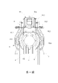
第一圖:本發明之正視圖 Figure 1: Front view of the present invention
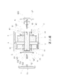
第二圖:本發明之剖視分解圖 Figure 2: Cross-sectional exploded view of the present invention
第三圖:本發明之剖視圖 Figure 3: Sectional view of the present invention
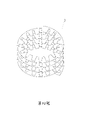
第四圖:本發明之定子捲繞狀態圖 The fourth figure: the stator winding state diagram of the present invention
第五圖:本發明之次一實施例正視圖 Figure 5: Front view of the second embodiment of the present invention
第六圖:本發明之再一實施例正視圖 Figure 6: Front view of another embodiment of the present invention
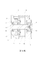
第七圖:本發明之另一實施例剖視圖 Figure 7: Cross-sectional view of another embodiment of the present invention
而為令本發明之技術手段及其所能達成之效果,能夠有更完整且清楚的揭露,茲詳細說明如下,請一併參閱揭露之圖式及圖號:首先,請參閱第一~三圖所示,為本發明之電梯曳引機結構,係主要設有一曳引機之機座(1),並於該機座(1)內設有一馬達容腔(11),且於該馬達容腔(11)其腔底中央處成型有一組立部(12),又於該組立部(12)套接有一定子(2),該定子(2)係由一長條形矽鋼片一體捲繞成一環圈體〔如第四圖所示〕,並使該定子(2)間隔設有數繞線槽,以於各繞線槽分別捲繞有一銅線之線圈,另於該馬 達容腔(11)內設有一轉子(3),且使該轉子(3)周側設有數磁鐵片(31),以環繞該定子(2)而設,而與該定子(2)對應設立,且於該轉子(3)中心組設有一出力軸(32),又於該組立部(12)設有一第一組孔(121),並於該第一組孔(121)組接有至少一第一軸承(13),且使該出力軸(32)後端穿接於該第一軸承(13),另設有一固定座(4),乃使該固定座(4)位於該機座(1)前側,而與該機座(1)前側相連結,並使該固定座(4)與機座(1)間形成一容置區間(41),該容置區間(41)左、右兩側係形成敞開之開口,且於該固定座(4)設有一第二組孔(42),又於該第二組孔(42)組接有至少一第二軸承(43),並使該出力軸(32)前端穿接於該第二軸承(43),另於該出力軸(32)上組接有一曳引輪(5),且使該曳引輪(5)位於該容置區間(41),而使該曳引輪(5)設置於該出力軸(32)中段位置處,又使該固定座(4)前側位於該第二組孔(42)處設有一旋轉編碼器(6),以與該出力軸(32)前端相對應,且使該出力軸(32)前端設有一插槽(321),以供該旋轉編碼器(6)其檢出梢(61)對應插設定位,另設有一護蓋(62),該護蓋(62)內面係成型有一嵌槽(621),且於該護蓋(62)周側設有數鎖孔,又使該護蓋(62)位於該固定座(4)前側,並將該旋轉編碼器(6)覆蓋於內,且使該旋轉編碼器(6)嵌設於該護蓋(62)內面之嵌槽(621),而於該護蓋(62)其各鎖孔分別穿設有一鎖固件(63),以與該固定座(4)預設之鎖孔對應鎖接結合,而將該旋轉編碼器(6)定位於該固定座(4)之第二組孔(42)中,另於該機座(1)後側蓋設有一封蓋(14),該封蓋(14)係於周側設有數鎖孔,且於該封蓋(14)其各鎖孔分別穿設有一鎖固件(15),以與該機座(1)後側預設之鎖孔對應鎖接結合,而將該機座(1)其第一組孔(121)後側予以覆蓋,以避免灰塵或異物等由該第一組孔(121)後側進人機座(1)內,又於該封蓋(14)外側處係可設置有一盤車(7),該盤車(7)係於中心成型有一多邊型銜接槽(71),另設有一盤車轉接器(72),該盤車轉接器(72)的一端係為一鎖接段(721),而相對另端為一多邊型銜接塊(722),乃使該盤車轉接器(72)之鎖接段(721)鎖固於該出力軸(32)後端中心處預設之插槽(322)中,又使該封蓋(14)於其中心處設有一穿 孔(141),且使該盤車轉接器(72)其多邊型銜接塊(722)位於該穿孔(141)外,以與該盤車(7)之多邊型銜接槽(71)對應接合,另於該固定座(4)上組設有一鋼索防脫板(8),且使該鋼索防脫板(8)覆蓋於該曳引輪(5)上方,又設有一煞車單元(9),該煞車單元(9)係可為一鼓式煞車(91),乃包含有一組設於機座(1)之煞車動力源(911),該煞車動力源(911)可為電磁閥,並使該煞車動力源(911)設有二相對傳動軸(912),又設有二煞車臂(913),並使該二煞車臂(913)分別位於該容置區間(41)左、右兩側之敞開之開口,且使該二煞車臂(913)上端各與一煞車動力源(911)之傳動軸(912)相組接,另使該二煞車臂(913)底端分別與該機座(1)相樞接,且使該二煞車臂(913)內面於對應該容置區間(41)左、右兩側之敞開之開口各設有一煞車片(914),而與該曳引輪(5)位置相對應,另於該煞車臂(913)於其上、下二端間與該機座(1)以一彈性組件(915)相組接。 In order to make the technical means of the present invention and the effects that can be achieved, more complete and clear disclosure, the detailed description is as follows, please refer to the disclosed drawings and drawing numbers: First, please refer to the first to third As shown in the figure, the elevator traction machine structure of the present invention is mainly provided with a machine base (1) of the traction machine, and a motor cavity (11) is arranged in the machine base (1), and the motor The cavity (11) has a set of vertical parts (12) formed at the center of the cavity bottom, and a stator (2) is sleeved on the set of vertical parts (12), and the stator (2) is integrally rolled by a long strip of silicon steel sheet It is wound into a ring body (as shown in the fourth figure), and the stator (2) is provided with several winding slots at intervals, so that a coil of copper wire is respectively wound in each winding slot, and another coil of copper wire is wound on the stator (2). A rotor (3) is arranged in the capacity chamber (11), and a number of magnet pieces (31) are arranged on the circumference of the rotor (3) to surround the stator (2) and set up corresponding to the stator (2). , and an output shaft (32) is arranged in the center of the rotor (3), and a first group of holes (121) is arranged in the assembly portion (12), and at least A first bearing (13), and the rear end of the output shaft (32) is passed through the first bearing (13), and a fixing seat (4) is provided, so that the fixing seat (4) is located on the machine seat (1) The front side is connected with the front side of the machine base (1), and a accommodating section (41) is formed between the fixing base (4) and the machine base (1). The accommodating section (41) is left, The right two sides are formed with open openings, and the fixing seat (4) is provided with a second group of holes (42), and at least one second bearing (43) is assembled in the second group of holes (42), and The front end of the output shaft (32) is connected to the second bearing (43), and a traction sheave (5) is assembled on the output shaft (32), and the traction sheave (5) is located in the accommodating section (41), so that the traction sheave (5) is arranged at the middle position of the output shaft (32), and a rotary encoder (6) is arranged on the front side of the fixed seat (4) at the second group of holes (42). ) to correspond to the front end of the output shaft (32), and a slot (321) is provided at the front end of the output shaft (32) for the detection pin (61) of the rotary encoder (6) to be inserted and set correspondingly There is also a protective cover (62), an insert groove (621) is formed on the inner surface of the protective cover (62), and a number of lock holes are arranged on the peripheral side of the protective cover (62), so that the protective cover (62) ) is located on the front side of the fixed seat (4), and covers the rotary encoder (6) inside, and makes the rotary encoder (6) embedded in the embedded groove (621) on the inner surface of the protective cover (62), A locking member (63) is respectively pierced through each locking hole of the protective cover (62), so as to be correspondingly locked and combined with the predetermined locking hole of the fixing seat (4), and the rotary encoder (6) is positioned. In the second set of holes (42) of the fixing seat (4), a cover (14) is provided on the rear side cover of the machine seat (1), and the cover (14) is provided with several locking holes on the peripheral side , and each locking hole of the cover (14) is respectively provided with a locking member (15), so as to be correspondingly locked and combined with the predetermined locking hole on the rear side of the base (1), and the base (1) ) The rear side of the first group of holes (121) is covered to prevent dust or foreign matter from entering the machine base (1) from the rear side of the first group of holes (121), and at the outer side of the cover (14) The system can be provided with a crank (7), the crank (7) is formed with a polygonal connecting groove (71) in the center, and a crank adapter (72) is also provided, and the crank adapter (72) One end is a locking section (721), and the opposite end is a polygonal connecting block (722), which enables the locking section (721) of the cranking adapter (72) to be locked to the output force In a preset slot (322) at the center of the rear end of the shaft (32), the cover (14) There is a wear A hole (141) is formed, and the polygonal engaging block (722) of the barring adapter (72) is located outside the through hole (141) so as to be correspondingly engaged with the polygonal connector groove (71) of the barring (7). , In addition, a steel cable anti-stripping plate (8) is arranged on the fixed seat (4), and the steel cable anti-stripping plate (8) is covered above the traction sheave (5), and a braking unit (9) is also provided, The braking unit (9) can be a drum brake (91), which includes a set of braking power sources (911) arranged on the machine base (1), the braking power source (911) can be a solenoid valve, and makes The braking power source (911) is provided with two opposite transmission shafts (912), and is further provided with two braking arms (913), and the two braking arms (913) are located on the left and right sides of the accommodating section (41) respectively The opening is opened, and the upper ends of the two brake arms (913) are respectively assembled with the transmission shaft (912) of a braking power source (911), and the bottom ends of the two brake arms (913) are respectively connected with the base. (1) They are pivotally connected, and the two brake arms (913) are provided with a brake pad (914) on the inside of the openings corresponding to the left and right sides of the accommodating section (41), and are connected with the traction sheave. (5) The positions correspond to each other, and the brake arm (913) is assembled with the base (1) by an elastic component (915) between its upper and lower ends.
據此,當本發明之曳引機於安裝前或使用前〔尤其是一段時間未使用時〕係可將該盤車(7)藉由盤車轉接器(72)以與出力軸(32)相連結,繼工作人員係可手握於盤車(7),以透過盤車(7)帶動出力軸(32)轉動,藉以手動檢測該出力軸(32)是否有異音干涉或生銹等情況,該手動檢測作業亦可於一般檢查維修時為之,當檢測合格後即可將盤車(7)分離取下。而後係可將本發明之曳引機安裝於建築物的電梯井,由於本發明係將旋轉編碼器(6)組設於該固定座(4)前側處,故機座(1)後側係可直接抵靠於電梯井牆壁,以節省本發明安裝時所佔空間,另當旋轉編碼器(6)發生故障須進行維修時,工作人員係可直接對該設於固定座(4)前側之旋轉編碼器(6)進行維修或更換,而省略將整個曳引機拆下,再將曳引機前後翻轉的步驟,以大幅提高旋轉編碼器(6)維修更換的便利性。再者,當停、斷電等造成電梯車廂停止運作時,藉由盤車轉接器(72)的設置係可簡便將盤車(7)組裝於盤車轉接器(72)後藉由手動方式,將電梯車廂作動至指定樓層,以利對關在電梯車廂內的人員或物品等提供救援者。 Accordingly, when the traction machine of the present invention is installed or used (especially when it has not been used for a period of time), the crank (7) can be connected to the output shaft (32) through the crank adapter (72). ), the staff can hold the crank (7) by hand to drive the output shaft (32) to rotate through the crank (7), so as to manually detect whether the output shaft (32) has abnormal noise interference or rust In other cases, the manual inspection operation can also be performed during general inspection and maintenance. When the inspection is qualified, the crank (7) can be separated and removed. Then, the traction machine of the present invention can be installed in the elevator shaft of the building. Since the rotary encoder (6) is assembled at the front side of the fixed seat (4) in the present invention, the rear side of the machine seat (1) is It can be directly abutted against the wall of the elevator shaft to save the space occupied by the present invention when it is installed. In addition, when the rotary encoder (6) fails and needs to be repaired, the staff can directly adjust the installation on the front side of the fixed seat (4). The rotary encoder (6) is repaired or replaced, and the steps of disassembling the entire traction machine and then turning the traction machine back and forth are omitted, so as to greatly improve the convenience of maintenance and replacement of the rotary encoder (6). Furthermore, when the elevator car stops running due to stopping, power failure, etc., the cranking adapter (72) can be installed to easily assemble the cranking adapter (72) and then use the cranking adapter (72). Manually, move the elevator car to the designated floor, so as to provide rescuers to the people or objects locked in the elevator car.
再者,當本發明之曳引機運作時,係供電予定子(2),以與轉子(3)間產生旋轉磁場,以驅使轉子(3)轉動,藉由該定子(2)以一矽鋼片一體捲繞成形設計,不僅可縮小定子(2)體積、減少矽鋼片素材浪費、縮短製造工時與降低繞組線圈高度,更可有效增加定子(2)各繞線槽內線圈的截面積,以提高繞組係數及增加線圈佔槽率,而達到提高單位面積電流量及提升轉矩與發電效率的效果。 Furthermore, when the traction machine of the present invention operates, power is supplied to the stator (2) to generate a rotating magnetic field with the rotor (3) to drive the rotor (3) to rotate. The integral winding design of the sheet can not only reduce the volume of the stator (2), reduce the waste of silicon steel sheet material, shorten the manufacturing time and reduce the height of the winding coil, but also effectively increase the cross-sectional area of the coil in each winding slot of the stator (2). In order to improve the winding coefficient and increase the slot ratio of the coil, the effect of increasing the current per unit area and improving the torque and power generation efficiency is achieved.
當轉子(3)經由出力軸(32)帶動相接之曳引輪(5)轉動時,利用曳引輪(5)其容設之容置區間(41)左、右兩側之敞開的開口設計,係可於曳引輪(5)轉動時,產生強制對流效果,以降曳引輪(5)等運轉時溫昇效應,並提高曳引輪(5)等運轉效率,隨之繞設於曳引輪(5)上之鋼索(a)係會牽引電梯車廂升、降作動,此時,與出力軸(32)前端位置相對應之旋轉編碼器(6)係會偵測出力軸(32)轉速,並轉換為電梯車廂位移的即時位置,而藉由將旋轉編碼器(6)之檢出梢(61)與出力軸(32)之插槽(321)配合插設定位設計,係可增加旋轉編碼器(6)之訊號解析度及訊號回饋速度,進而達到提升控制精度功效。 When the rotor (3) drives the connected traction sheave (5) to rotate through the output shaft (32), the open openings on the left and right sides of the accommodating section (41) of the traction sheave (5) are used, The system can produce forced convection effect when the traction sheave (5) rotates, so as to reduce the temperature rise effect of the traction sheave (5) during operation, and improve the operation efficiency of the traction sheave (5), and then it is wound around the traction sheave (5) The wire rope (a) above will pull the elevator car up and down. At this time, the rotary encoder (6) corresponding to the front end position of the output shaft (32) will detect the rotation speed of the output shaft (32) and convert it into The real-time position of the displacement of the elevator car, and by matching the detection pin (61) of the rotary encoder (6) with the slot (321) of the output shaft (32) to insert the setting design, the rotary encoder (6) can be added. ) of the signal resolution and signal feedback speed, thereby achieving the effect of improving the control accuracy.
而當電梯車廂到達預設樓層欲暫停運作時,係驅動該鼓式煞車(91)之煞車動力源(911),以使該煞車動力源(911)之二傳動軸(912)分別帶動二煞車臂(913)作動,而使二煞車臂(913)組設之煞車片(914)分別經由容置區間(41)左、右兩側敞開之開口進入容置區間(41)內,以抵壓於曳引輪(5)兩側,以停止曳引輪(5)的轉動,而達到使電梯車廂停止於所需樓層位置的效果。當欲釋放對曳引輪(5)制動時,則使煞車動力源(911)之二傳動軸(912)帶動二煞車臂(913)復位,以使二煞車臂(913)上之煞車片(914)脫離對曳引輪(5)的抵壓,即可使曳引輪(5)回復運轉,以帶動電梯車廂升、降運作。 And when the elevator car reaches the preset floor and wants to suspend operation, the brake power source (911) of the drum brake (91) is driven, so that the two drive shafts (912) of the brake power source (911) drive the two brakes respectively The arm (913) is actuated, so that the brake pads (914) assembled by the two brake arms (913) enter the accommodating area (41) through the openings on the left and right sides of the accommodating area (41) respectively, so as to press against On both sides of the traction sheave (5), the rotation of the traction sheave (5) is stopped, so as to achieve the effect of stopping the elevator car at a desired floor position. When the braking of the traction sheave (5) is to be released, the two drive shafts (912) of the braking power source (911) drive the two brake arms (913) to reset, so that the brake pads (914) on the two brake arms (913) are reset. ) is released from the pressing on the traction sheave (5), so that the traction sheave (5) can be returned to run, so as to drive the elevator car to move up and down.
另本發明之出力軸(32)係藉由其前、後二端所設之第一軸承(13)與第二軸承(43)的支撐,與使曳引輪(5)位於出力軸(32)中段位置設計,即可避免因車廂重量、平衡配重、人員載重及反作用力等產生徑向負載,透過曳引輪(5)作 用於出力軸(32)時,造成出力軸(32)產生偏心的問題,另作用於出力軸(32)之徑向負載更可透過第一軸承(13)及第二軸承(43)傳遞至機座(1)及固定座(4),以將出力軸(32)承受的徑向負載平均分散,以避免造成出力軸(32)提早發生斷裂損壞。此外,本發明藉由覆蓋於曳引輪(5)上方之鋼索防脫板(8)設置,係可有效止擋曳引輪(5)上之鋼索(a)發生跳脫情形,以使鋼索(a)維持井然有序繞設於曳引輪(5)上狀態,以利電梯車廂升降的順暢、穩定性,而當鋼索(a)欲發生跳脫時,該鋼索防脫板(8)係具有減速煞車功能,以避免危險產生,為一可增強電梯裝置安全性之安全結構。 In addition, the output shaft (32) of the present invention is supported by the first bearing (13) and the second bearing (43) provided at the front and rear ends, so that the traction sheave (5) is located on the output shaft (32) The design of the middle position can avoid radial load caused by the weight of the carriage, the balance weight, the personnel load and the reaction force. When used for the output shaft (32), the problem of eccentricity of the output shaft (32) is caused, and the radial load acting on the output shaft (32) can be transmitted to the output shaft (32) through the first bearing (13) and the second bearing (43). The machine base (1) and the fixing base (4) are used to evenly disperse the radial load borne by the output shaft (32), so as to prevent the output shaft (32) from being broken and damaged in advance. In addition, the present invention can effectively prevent the wire rope (a) on the traction sheave (5) from jumping out by means of the wire rope anti-separation plate (8) covering the top of the traction sheave (5), so that the wire rope (a) ) to maintain an orderly winding state on the traction sheave (5) to facilitate the smooth and stable lifting of the elevator car, and when the wire rope (a) is about to jump out, the wire rope anti-separation plate (8) has a deceleration Braking function to avoid danger, it is a safety structure that can enhance the safety of elevator installations.
再者,本發明之煞車單元(9)除為鼓式煞車(91)外,請一併參閱第五圖所示,也可為一板式煞車(92),該板式煞車(92)係主要於該機座(1)左、右兩側處各組設有一煞車動力源(921),該煞車動力源(921)係可為電磁閥,又使該煞車動力源(921)之傳動軸組接有一磁性煞車片(922),且使該二磁性煞車片(922)分別位於該容置區間(41)左、右兩側敞開之開口處,而與該曳引輪(5)位置相對應,藉此,當啟動二煞車動力源(921)作動時,即可帶動二磁性煞車片(922)靠近該曳引輪(5),以利磁性停止曳引輪(5)轉動,達到磁性煞車效果。請一併參閱第六圖所示,另本發明之煞車單元(9)也可採盤式煞車(93),該盤式煞車(93)係包含有一組設於機座(1)之煞車動力源,並使該煞車動力源連結一煞車片,且使該煞車片位於該機座(1)後側,而與該轉子(3)其出力軸(32)後端位置相對應,當煞車動力源推動煞車片壓掣於出力軸(32)後端時,即可經由出力軸(32)達到停止曳引輪(5)轉動效果。另亦可配合客戶使用所需,將鼓式煞車(91)與盤式煞車(93)組合使用,或將板式煞車(92)及盤式煞車(93)組合使用,以提高對曳引輪(5)的煞車效率。 Furthermore, the brake unit (9) of the present invention is not only a drum brake (91), please refer to the fifth figure, but also a plate brake (92). The plate brake (92) is mainly used in the A braking power source (921) is provided on each of the left and right sides of the machine base (1), the braking power source (921) can be a solenoid valve, and the drive shaft of the braking power source (921) is assembled There is a magnetic brake piece (922), and the two magnetic brake pieces (922) are located at the openings on the left and right sides of the accommodating section (41) respectively, and correspond to the position of the traction sheave (5). Therefore, when the two brake power sources (921) are activated, the two magnetic brake pads (922) can be driven close to the traction sheave (5), so as to magnetically stop the rotation of the traction sheave (5) and achieve the magnetic braking effect. Please also refer to the sixth figure. In addition, the brake unit (9) of the present invention can also adopt a disc brake (93), and the disc brake (93) includes a set of braking power provided on the machine base (1). The brake power source is connected to a brake pad, and the brake pad is located on the rear side of the frame (1), and corresponds to the rear end position of the output shaft (32) of the rotor (3). When the braking power When the source pushes the brake pad to press the rear end of the output shaft (32), the effect of stopping the rotation of the traction sheave (5) can be achieved through the output shaft (32). In addition, the drum brake (91) can be combined with the disc brake (93), or the plate brake (92) and the disc brake (93) can be combined according to the needs of the customer, so as to improve the resistance to the traction wheel (5). ) braking efficiency.
另本發明除可將定子(2)套接於機座(1)其馬達容腔(11)中央之組立部(12),並使轉子(3)之磁鐵片(31)環繞該定子(2)而設,以構成外轉子型態外〔如第二圖所示〕。請一併參閱第七圖所示,也可將轉子(3)設於該馬達容腔(11)其組 立部(12)端面處,且於該轉子(3)周側組設有數磁鐵片(31),又使該定子(2)組設於馬達容腔(11)的腔壁,而使定子(2)環繞該轉子(3)周側之磁鐵片(31)而設,以構成內轉子型態。另本發明亦可依客戶使用所需,選擇將旋轉編碼器(6)組裝於前側之固定座(4)或後側之機座(1),當欲將旋轉編碼器(6)安裝於機座(1)後側時,係將旋轉編碼器(6)裝設於機座(1)之第一組孔(121)處,並將旋轉編碼器(6)其檢出梢(61)對應插設於該出力軸(32)後端之插槽(322),再以護蓋(62)覆蓋該旋轉編碼器(6)後,以鎖固件將護蓋(62)與機座(1)鎖接結合,而將該旋轉編碼器(6)定位於該機座(1)之第一組孔(121)中,當將旋轉編碼器(6)換裝於機座(1)後側時,係可將盤式煞車(93)之煞車動力源安裝於該固定座(4),以使其煞車片對出力軸(32)前端進行煞車動作。另當旋轉編碼器(6)安裝於機座(1)後側時,則可將盤車轉接器(72)換裝於出力軸(32)前端之插槽(321),再使封蓋(14)與該固定座(4)前側蓋設結合,依此,同樣可將盤車(7)藉由盤車轉接器(72)而與出力軸(32)相連結,以便利以手動檢測出力軸(32)是否有異音干涉或生銹等,另也可於電梯車廂停止運作時,以盤車(7)將電梯車廂帶動至指定樓層,以利對關在電梯車廂內的人員或物品等提供救援者。 In addition, in the present invention, the stator (2) can be sleeved on the assembly part (12) in the center of the motor cavity (11) of the machine base (1), and the magnet pieces (31) of the rotor (3) can surround the stator (2). ) to form the outer rotor shape (as shown in the second figure). Please refer to Figure 7 together, the rotor (3) can also be arranged in the motor cavity (11) and its assembly At the end face of the vertical portion (12), a number of magnet pieces (31) are arranged on the peripheral side of the rotor (3), and the stator (2) is arranged on the cavity wall of the motor cavity (11), so that the stator ( 2) The magnet pieces (31) on the peripheral side of the rotor (3) are arranged around the rotor (3) to form an inner rotor type. In addition, the present invention can also choose to assemble the rotary encoder (6) on the fixed seat (4) on the front side or the base (1) on the rear side according to the needs of customers. When the rotary encoder (6) is to be installed on the machine On the rear side of the base (1), the rotary encoder (6) is installed at the first group of holes (121) of the base (1), and the detection pin (61) of the rotary encoder (6) corresponds to the first group of holes (121). Inserted into the slot (322) at the rear end of the output shaft (32), after covering the rotary encoder (6) with a protective cover (62), the protective cover (62) and the base (1) are fastened with a locking member The rotary encoder (6) is positioned in the first group of holes (121) of the base (1) by locking and coupling, and when the rotary encoder (6) is replaced on the rear side of the base (1) , the braking power source of the disc brake (93) can be installed on the fixed seat (4), so that its brake pads can perform braking action on the front end of the output shaft (32). In addition, when the rotary encoder (6) is installed on the rear side of the machine base (1), the cranking adapter (72) can be replaced with the slot (321) at the front end of the output shaft (32), and then the cover is closed. (14) is combined with the front side cover of the fixing seat (4), according to this, the crank (7) can also be connected with the output shaft (32) through the crank adaptor (72), so as to facilitate manual operation Detect whether there is abnormal noise interference or rust on the output shaft (32), and also when the elevator car stops running, the elevator car can be driven to the designated floor by the crank (7), so as to facilitate the personnel locked in the elevator car. or items, etc. to provide rescuers.
由上述結構及實施方式可知,本發明係具有如下優點: As can be seen from the above structure and implementation, the present invention has the following advantages:
1.本發明之電梯曳引機結構係於曳引機之出力軸前、後端各設有軸承支撐,並使曳引輪位於出力軸中段位置,藉此,即可避免曳引機作動時產生的徑向負載,作用於出力軸上造成出力軸產生偏心問題,以利提高曳引機的使用壽命。 1. The elevator traction machine structure of the present invention is provided with bearings at the front and rear of the output shaft of the traction machine, and the traction sheave is located in the middle of the output shaft, thereby avoiding the occurrence of The radial load acts on the output shaft, causing the eccentricity problem of the output shaft, so as to improve the service life of the traction machine.
2.本發明之電梯曳引機結構係於曳引機之出力軸前、後端各設有軸承支撐,於此,作用於出力軸之徑向負載係可透過軸承傳遞於其所組設之機座及固定座,而將出力軸所受徑向負載平均分散,以避免造成出力軸提早產生斷裂損壞情形。 2. The elevator traction machine structure of the present invention is provided with bearings at the front and rear of the output shaft of the traction machine. Here, the radial load acting on the output shaft can be transmitted through the bearings to the assembled components. The machine base and the fixed seat, and evenly disperse the radial load on the output shaft, so as to avoid premature fracture and damage of the output shaft.
3.本發明之電梯曳引機結構係將旋轉編碼器設於曳引機前側,藉此,當旋轉編碼器發生故障須維修時,工作人員係可直接對該設於曳引機前側之旋轉編碼器進行維修或更換,以省略將整個曳引機拆下再將曳引機前後翻轉步驟,以提高旋轉編碼器維修更換的便利性。 3. In the elevator traction machine structure of the present invention, the rotary encoder is arranged on the front side of the traction machine, so that when the rotary encoder fails and needs to be repaired, the staff can directly adjust the rotary encoder on the front side of the traction machine. The encoder is repaired or replaced, so as to omit the steps of removing the entire traction machine and then turning the traction machine back and forth, so as to improve the convenience of the maintenance and replacement of the rotary encoder.
4.本發明之電梯曳引機結構係將旋轉編碼器設於曳引機前側,以避免旋轉編碼器凸設於機座後側情形,而使曳引機的機座後側可直接抵靠於電梯井牆壁,以節省曳引機安裝時所佔空間,以利曳引機最佳擺放之規畫。 4. The elevator traction machine structure of the present invention sets the rotary encoder on the front side of the traction machine, so as to avoid the situation that the rotary encoder is protruded on the back side of the machine base, so that the back side of the machine base of the traction machine can directly abut against On the wall of the elevator shaft, to save the space occupied by the traction machine during installation, and to facilitate the planning of the best placement of the traction machine.
5.本發明之電梯曳引機結構係於曳引輪上方覆蓋有一鋼索防脫板,藉此,即可避免曳引輪上之鋼索發生跳脫情形,當鋼索欲發生跳脫時,該鋼索防脫板係具有減速煞車功能,以避免危險產生,為一可增強電梯裝置安全性之安全結構。 5. The elevator hoisting machine structure of the present invention is covered with a steel cable anti-dropping plate above the traction sheave, whereby the steel cable on the traction sheave can be prevented from jumping off. The plate system has the function of deceleration and braking to avoid danger and is a safety structure that can enhance the safety of the elevator installation.
6.本發明之電梯曳引機結構係使定子由一矽鋼片一體捲繞成形,於此,即可省略數多矽鋼片疊積程序,以大幅節省製造工時,另亦可減少數多矽鋼片各別沖壓成形時的素材浪費,以及避免數多矽鋼片因沖壓變形或毛邊等,於堆疊後體積過大情形,而可有效縮小定子體積,另於定子體積縮小情況下,即可相對增加定子各繞線槽內線圈的截面積,以提高線圈的佔槽率與繞組係數,進而達到提高單位面積電流量及提升轉矩與發電效率的效果。 6. The elevator traction machine structure of the present invention is that the stator is formed by integrally winding one silicon steel sheet. In this case, the stacking process of several silicon steel sheets can be omitted, which can greatly save the manufacturing time, and can also reduce the number of silicon steel sheets. It can effectively reduce the volume of the stator when the volume of the sheet is too large due to stamping deformation or burrs, and can effectively reduce the volume of the stator. In addition, when the volume of the stator is reduced, the stator can be relatively increased. The cross-sectional area of the coil in each winding slot is used to increase the slot occupancy rate and winding coefficient of the coil, thereby achieving the effect of increasing the current per unit area and improving the torque and power generation efficiency.
7.本發明之電梯曳引機結構係使機座與固定座間形成的容置區間左、右兩側形成敞開之開口,藉此設計係可於曳引輪轉動時,產生強制對流效果,以降低曳引輪等運轉時溫昇效應,並提曳引輪等的運轉效率。 7. The elevator traction machine structure of the present invention forms open openings on the left and right sides of the accommodating area formed between the machine base and the fixed seat, so that the design can produce forced convection when the traction sheave rotates, so as to reduce the The temperature rise effect of the traction sheave, etc. during operation, and the operation efficiency of the traction sheave, etc. is improved.
8.本發明之電梯曳引機結構係於轉子之出力軸端部設有一插槽,以供旋轉編碼器之檢出梢插設固定於內,依此設計係可增加旋轉編碼器之訊號解析度及訊號回饋速度,進而提升控制精度。 8. The elevator traction machine structure of the present invention is provided with a slot at the end of the output shaft of the rotor, so that the detection pin of the rotary encoder can be inserted and fixed in it. According to this design, the signal analysis of the rotary encoder can be increased. speed and signal feedback speed, thereby improving the control accuracy.
9.本發明之電梯曳引機結構係可適用鼓式煞車、板式煞車及盤式煞車等各式煞車,且可配合客戶使用所需,將鼓式煞車與盤式煞車組合使用,或將板式煞車與盤式煞車組合使用,以更有效提高對曳引輪的煞車效率。 9. The elevator traction machine structure of the present invention can be applied to various types of brakes such as drum brakes, plate brakes and disc brakes, and can be used in combination with The brake is used in combination with the disc brake to more effectively improve the braking efficiency of the traction sheave.
10.本發明之電梯曳引機結構係使旋轉編碼器利用一護蓋定位,藉此,係可依客戶使用所需,選擇將旋轉編碼器組裝於前側之固定座或後側之機座,當欲變換旋轉編碼器安裝位置時,只須解除護蓋與固定座或機座之鎖接,即可將旋轉編碼器取下換裝於所需位置,以提高旋轉編碼器安裝換位的便利性。 10. The elevator traction machine structure of the present invention uses a protective cover to locate the rotary encoder, so that the rotary encoder can be assembled on the fixed seat on the front side or the machine seat on the rear side according to the needs of customers. When you want to change the installation position of the rotary encoder, you only need to release the lock between the cover and the fixed base or the base, and then the rotary encoder can be removed and replaced in the desired position, so as to improve the convenience of the rotary encoder installation and transposition sex.
11.本發明之電梯曳引機結構係於其出力軸相對旋轉編碼器的另端鎖接有一盤車轉接器,以便利與盤車進行組裝,於此,藉由盤車即可手動驅使出力軸轉動,以檢測出力軸是否有異音干涉或生銹等情況,又或當停、斷電等造成電梯車廂停止運作時,也可藉由盤車對關在電梯車廂內的人員或物品等進行救援者。 11. The structure of the elevator traction machine of the present invention is that a crank adapter is locked at the other end of the output shaft relative to the rotary encoder, so as to facilitate the assembly with the crank. Here, the crank can be manually driven. The output shaft rotates to detect whether there is abnormal noise interference or rust on the output shaft, or when the elevator car stops running due to stop or power failure, the people or items locked in the elevator car can also be checked by cranking. Waiting for rescuers.
綜上所述,本發明之實施例確能達到所預期功效,又其所揭露之具體構造,不僅未曾見諸於同類產品中,亦未曾公開於申請前,誠已完全符合專利法之規定與要求,爰依法提出發明專利之申請,懇請惠予審查,並賜准專利,則實感德便。 To sum up, the embodiments of the present invention can indeed achieve the expected effects, and the specific structures disclosed have not only not been seen in similar products, but also have not been disclosed before the application, which fully complies with the provisions of the patent law and Request, to file an application for an invention patent in accordance with the law, and entreat it to be reviewed and granted a patent, it is truly a virtue.
1:機座 11:馬達容腔 12:組立部 121:第一組孔 13:第一軸承 14:封蓋 141:穿孔 15:鎖固件 2:定子 3:轉子 31:磁鐵片 32:出力軸 321:插槽 322:插槽 4:固定座 41:容置區間 42:第二組孔 43:第二軸承 5:曳引輪 6:旋轉編碼器 61:檢出梢 62:護蓋 621:嵌槽 7:盤車 71:銜接槽 72:盤車轉接器 721:鎖接段 722:銜接塊 8:鋼索防脫板 1: base 11: Motor cavity 12: Assembly Department 121: The first group of holes 13: The first bearing 14: capping 141: Perforation 15: Lock firmware 2: Stator 3: Rotor 31: Magnet sheet 32: Output shaft 321: slot 322: slot 4: Fixed seat 41: accommodating interval 42: The second group of holes 43: Second bearing 5: Traction wheel 6: Rotary encoder 61: Detection tip 62: Cover 621: Groove 7: crank 71: Engagement slot 72: crank adapter 721: Locking Section 722: Articulation Block 8: Steel cable anti-drop plate
Claims (8)
Priority Applications (1)
| Application Number | Priority Date | Filing Date | Title |
|---|---|---|---|
| TW109136285A TWI764330B (en) | 2020-10-20 | 2020-10-20 | Elevator tractor |
Applications Claiming Priority (1)
| Application Number | Priority Date | Filing Date | Title |
|---|---|---|---|
| TW109136285A TWI764330B (en) | 2020-10-20 | 2020-10-20 | Elevator tractor |
Publications (2)
| Publication Number | Publication Date |
|---|---|
| TW202216575A TW202216575A (en) | 2022-05-01 |
| TWI764330B true TWI764330B (en) | 2022-05-11 |
Family
ID=82558577
Family Applications (1)
| Application Number | Title | Priority Date | Filing Date |
|---|---|---|---|
| TW109136285A TWI764330B (en) | 2020-10-20 | 2020-10-20 | Elevator tractor |
Country Status (1)
| Country | Link |
|---|---|
| TW (1) | TWI764330B (en) |
Citations (1)
| Publication number | Priority date | Publication date | Assignee | Title |
|---|---|---|---|---|
| CN204224045U (en) * | 2014-10-22 | 2015-03-25 | 歌拉瑞电梯有限公司 | A kind of inorganic shell Double-support-type towing machine |
-
2020
- 2020-10-20 TW TW109136285A patent/TWI764330B/en active
Patent Citations (1)
| Publication number | Priority date | Publication date | Assignee | Title |
|---|---|---|---|---|
| CN204224045U (en) * | 2014-10-22 | 2015-03-25 | 歌拉瑞电梯有限公司 | A kind of inorganic shell Double-support-type towing machine |
Also Published As
| Publication number | Publication date |
|---|---|
| TW202216575A (en) | 2022-05-01 |
Similar Documents
| Publication | Publication Date | Title |
|---|---|---|
| US5226508A (en) | Disc brake for elevator drive sheave | |
| AU696150B2 (en) | Integrated elevator drive machine and brake assembly | |
| KR20000071529A (en) | Elevator traction machine | |
| JP6405053B2 (en) | Elevator hoisting machine and elevator | |
| JP2000514162A (en) | Electromagnetically releasable friction safety brake | |
| US7637357B2 (en) | Elevator apparatus with sheave rotational speed difference determination for detecting an abnormality | |
| JP5824149B2 (en) | Elevator electromagnetic brake release device | |
| KR100430113B1 (en) | Elevator | |
| KR20140137278A (en) | Descending device for escape | |
| TWI667185B (en) | An additional braking device for a step sprocket shaft of an escalator | |
| US5156239A (en) | Disc brake/load weighing assembly for elevator drive sheave | |
| JP5254232B2 (en) | Elevator hoist brake with integral bearing and brake surface | |
| TWI764330B (en) | Elevator tractor | |
| JP4952296B2 (en) | Release device for brake for elevator hoist and method for releasing the brake | |
| JP4118641B2 (en) | Elevator hoisting machine | |
| JP2016034872A (en) | Hoist for elevator | |
| JP4476809B2 (en) | Elevator drive device | |
| WO2014064752A1 (en) | Elevator pulley device | |
| TWM606623U (en) | Elevator traction machine structure | |
| KR20020062284A (en) | Lift with a car attached to a support | |
| JP3230349U6 (en) | Structure of elevator hoist | |
| JP3230349U (en) | Elevator hoisting machine structure | |
| JP4408347B2 (en) | Elevator hoisting machine | |
| JP4312553B2 (en) | Traction elevator hoisting machine | |
| WO2006011214A1 (en) | Hoist for elevator |