TWI754336B - External circulation ball screw and return pipe structure thereof - Google Patents
External circulation ball screw and return pipe structure thereof Download PDFInfo
- Publication number
- TWI754336B TWI754336B TW109125533A TW109125533A TWI754336B TW I754336 B TWI754336 B TW I754336B TW 109125533 A TW109125533 A TW 109125533A TW 109125533 A TW109125533 A TW 109125533A TW I754336 B TWI754336 B TW I754336B
- Authority
- TW
- Taiwan
- Prior art keywords
- return
- ball screw
- groove
- nut
- pipe structure
- Prior art date
Links
- 230000003134 recirculating effect Effects 0.000 claims description 5
- 238000000034 method Methods 0.000 abstract description 3
- 238000010586 diagram Methods 0.000 description 4
- 239000004020 conductor Substances 0.000 description 2
- 238000009434 installation Methods 0.000 description 2
- 238000001746 injection moulding Methods 0.000 description 1
- 230000008450 motivation Effects 0.000 description 1
- 238000005096 rolling process Methods 0.000 description 1
Images


Landscapes
- Transmission Devices (AREA)
Abstract
Description
本發明係有關於滾珠螺桿,尤指一種外循環滾珠螺桿的結構。 The present invention relates to a ball screw, especially a structure of an external circulation ball screw.
傳統外循環滾珠螺桿是由螺桿、螺帽、滾珠及迴流管等結構所組合,其設置方式是將螺帽套設在螺桿上,另將迴流管裝設在螺帽外部,最後再將滾珠設置在螺桿與螺帽中;藉此,滾珠會從螺帽的螺旋溝槽進入彎管,再通過迴流管回到螺旋溝槽而作無限循環運動。 The traditional external circulation ball screw is composed of a screw, a nut, a ball and a return pipe. In the screw and the nut; thereby, the balls will enter the elbow from the helical groove of the nut, and then return to the helical groove through the return pipe to make an infinite circular motion.
再者,習知外循環滾珠螺桿的迴流管大多是由塑料一體式射出成型或由上、下兩個半迴流殼座所構成,並使迴流管的兩端與螺桿和螺帽所構成的負荷路徑連接而構成循環路徑。然而,現有的迴流管結構需在螺帽上設置倒角,用以承置伸入螺帽的迴流殼座;惟,此倒角與迴流殼座之間經常有組設上的公差而形成斷差面,此斷差面會導致滾珠在循環的過程中受阻,進而影響循環時的順暢度而有待加以改善。 In addition, most of the return pipes of the conventional external circulation ball screw are made of plastic integral injection molding or composed of upper and lower semi-return shells, and the two ends of the return pipe are connected to the load formed by the screw and the nut. The paths are connected to form a circular path. However, in the existing structure of the return pipe, a chamfer needs to be provided on the nut to accommodate the return housing that extends into the nut; however, there is often a tolerance in the assembly between the chamfer and the return housing, which results in a fracture. The difference surface will cause the ball to be blocked during the cycle, which will affect the smoothness of the cycle and needs to be improved.
有鑑於此,本發明人遂針對上述現有技術,特潛心研究並配合學理的運用,盡力解決上述之問題點,即成為本發明人之研究動機。 In view of this, the inventor of the present invention has devoted himself to the research on the above-mentioned prior art and cooperated with the application of theories, and tried his best to solve the above-mentioned problems, which is the research motivation of the present inventor.
本發明之一目的,在於提供一種外循環滾珠螺桿的迴流管結構,以使外循環滾珠螺桿的滾珠在循環運動的過程中更為順暢。 One of the objectives of the present invention is to provide a return pipe structure of the external circulation ball screw, so that the balls of the external circulation ball screw can be more smoothly in the process of circulating movement.
本發明之一目的,在於提供一種外循環滾珠螺桿的迴流管結構,其外殼座及螺帽在結合上保有較大的組合公差,藉此提高螺帽及迴流管結構的良率。 One object of the present invention is to provide a return pipe structure of an external circulation ball screw, wherein the outer shell seat and the nut have a large combined tolerance on the combination, thereby improving the yield of the nut and the return pipe structure.
為了達成上述之目的,本發明係為一種外循環滾珠螺桿的迴流管結構,用以組合在套設有螺帽的螺桿上。螺帽具有螺旋溝槽及連通螺旋溝槽的迴流通道,迴流管結構包括內殼座及外殼座。內殼座設置在迴流通道上。外殼座對應結合在內殼座上,外殼座具有外迴流槽及設置在外迴流槽二端的一對外定位塊,各外定位塊伸入迴流通道並連通螺旋溝槽,各外定位塊具有導接面,導接面自外迴流槽的內壁面延伸並成型有尖末端而銜接螺旋溝槽的弧形內壁面。 In order to achieve the above-mentioned purpose, the present invention is a return pipe structure of an external circulation ball screw, which is used to be assembled on a screw sleeve with a nut. The nut has a spiral groove and a return channel communicating with the spiral groove, and the return pipe structure includes an inner shell seat and an outer shell seat. The inner housing seat is arranged on the return channel. The outer shell seat is correspondingly combined with the inner shell seat. The outer shell seat has an outer return groove and a pair of outer positioning blocks arranged at both ends of the outer return groove. Each outer positioning block extends into the return channel and communicates with the spiral groove. Each outer positioning block has a guide surface , the guide surface extends from the inner wall surface of the outer reflow groove and is formed with a pointed end to connect with the arc-shaped inner wall surface of the spiral groove.
為了達成上述之目的,本發明係為一種外循環滾珠螺桿,包括螺桿、螺帽及迴流管結構。螺帽套設在螺桿上,螺帽具有複數螺旋溝槽並在一側面設有連通螺旋溝槽的迴流通道。迴流管結構包括內殼座及外殼座。內殼座設置在迴流通道上。外殼座對應結合在內殼座上,外殼座具有外迴流槽及設置在外迴流槽二端的一對外定位塊,各外定位塊伸入迴流通道並連通螺旋溝槽,各外定位塊具有導接面,導接面自外迴流槽的內壁面延伸並成型有尖末端而銜接螺旋溝槽的弧形內壁面。 In order to achieve the above-mentioned purpose, the present invention is an external circulation ball screw, including a screw, a nut and a return pipe structure. The nut is sleeved on the screw, and the nut has a plurality of helical grooves and a return channel which communicates with the helical grooves is arranged on one side. The return pipe structure includes an inner shell seat and an outer shell seat. The inner housing seat is arranged on the return channel. The outer shell seat is correspondingly combined with the inner shell seat. The outer shell seat has an outer return groove and a pair of outer positioning blocks arranged at both ends of the outer return groove. Each outer positioning block extends into the return channel and communicates with the spiral groove. Each outer positioning block has a guide surface , the guide surface extends from the inner wall surface of the outer reflow groove and is formed with a pointed end to connect with the arc-shaped inner wall surface of the spiral groove.
相較於習知,本發明之外循環滾珠螺桿的迴流管結構的外殼座具有外迴流槽及一對外定位塊,各外定位塊具有導接面並成型有尖末端而銜接螺旋溝槽的弧形內壁面;據此,外殼座透過導接面及其尖末端而貼接螺旋溝槽的 弧形內壁面,藉以省卻傳統在螺帽內壁面設置倒角而需進行二次加工的程序,並使外殼座及螺旋溝槽之間呈連續銜接而不致出現斷差面,提供滾珠在循環的過程中保持順暢滾動;又,本發明透過尖末端的設置可提供外殼座及螺帽在結合上保有較大的組合公差,藉以提高螺帽及迴流管結構的良率,增加本發明的實用性。 Compared with the prior art, the outer shell seat of the return pipe structure of the external recirculating ball screw of the present invention has an external return groove and a pair of external positioning blocks. According to this, the housing seat is attached to the helical groove through the guide surface and its pointed end. The arc-shaped inner wall avoids the need for secondary processing of the traditional chamfering on the inner wall of the nut, and makes the shell seat and the helical groove connect continuously without a section surface, providing the balls in the circulation. During the process, smooth rolling is maintained; in addition, the present invention can provide the housing seat and the nut with a large combined tolerance on the combination through the arrangement of the pointed end, so as to improve the yield rate of the nut and the return pipe structure, and increase the practicability of the present invention .
1:外循環滾珠螺桿 1: External circulation ball screw
10:螺桿 10: Screw
11:軸桿 11: Shaft
20:螺帽 20: Nut
21:迴流通道 21: Return channel
22:螺旋溝槽 22: Spiral groove
23:安裝孔 23: Mounting holes
230:斜邊 230: hypotenuse
30:迴流管結構 30: return pipe structure
40:內殼座 40: Inner shell seat
41:內迴流槽 41: Internal reflow tank
411:定位凸塊 411: Positioning bump
42:內定位塊 42: Internal positioning block
420:斜輪廓 420: Oblique profile
50:外殼座 50: Shell seat
501:平面 501: Flat
51:外迴流槽 51: External reflow tank
511:定位槽 511: Positioning slot
52:外定位塊 52: External positioning block
520:斜輪廓 520: Oblique profile
521:導接面 521: Conductor surface
522:尖末端 522: tip end
523:凹口 523: Notch
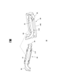
圖1係本發明之外循環滾珠螺桿的立體分解示意圖。 Fig. 1 is a perspective exploded schematic view of a recirculating ball screw outside the present invention.
圖2係為本發明之迴流管結構的立體分解示意圖。 FIG. 2 is a perspective exploded schematic view of the structure of the return pipe of the present invention.
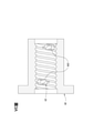
圖3A係為本發明之螺帽的剖視圖。 3A is a cross-sectional view of the nut of the present invention.
圖3B係為分別為本發明之迴流管結構的平面分解圖。 3B is an exploded plan view of the structure of the return pipe of the present invention, respectively.
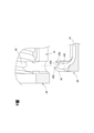
圖4係為本發明之外殼座與螺帽的結合示意圖。 FIG. 4 is a schematic diagram of the combination of the housing base and the nut of the present invention.
圖5係為本發明之外殼座與螺帽的結合剖視圖。 FIG. 5 is a cross-sectional view of the combination of the housing base and the nut of the present invention.
圖6係為本發明之螺帽及迴流管結構的部分剖視圖。 6 is a partial cross-sectional view of the structure of the nut and the return pipe of the present invention.
圖7係為本發明之外循環滾珠螺桿及迴流管結構的組合剖視圖。 FIG. 7 is a combined cross-sectional view of the structure of the circulating ball screw and the return pipe outside the present invention.
圖8係為圖7的局部放大示意圖。 FIG. 8 is a partial enlarged schematic view of FIG. 7 .
有關本發明之詳細說明及技術內容,配合圖式說明如下,然而所附圖式僅提供參考與說明用,並非用來對本發明加以限制者。 The detailed description and technical content of the present invention are described below in conjunction with the drawings. However, the accompanying drawings are only for reference and description, and are not intended to limit the present invention.
請參照圖1及圖2,係分別為本發明之外循環滾珠螺桿的立體分解示意圖及迴流管結構的立體分解示意圖。本發明為一種外循環滾珠螺桿1,包
括一螺桿10、一螺帽20及一迴流管結構30。該螺帽20套設在該螺桿10上,該迴流管結構30組合在套設有該螺帽20的螺桿10上,據以構成該外循環滾珠螺桿1的迴流管結構。更詳細描述該外循環滾珠螺桿1的結構如後。
Please refer to FIG. 1 and FIG. 2 , which are a perspective exploded schematic diagram of a recirculating ball screw outside the present invention and a perspective exploded schematic diagram of the structure of the return pipe, respectively. The present invention is an external
如圖1所示,該螺桿10具有一軸桿11。又,該螺帽20套設在該螺桿10上,該螺帽20的內壁面對應該軸桿11成型有複數螺旋溝槽22且在一側面設有連通該些螺旋溝槽22的一迴流通道21。
As shown in FIG. 1 , the
再者,該迴流管結構30結合在該螺帽20的迴流通道21上,包括一內殼座40及一外殼座50。該內殼座40及該外殼座50相互定位及罩合,並組合在該螺帽20的迴流通道21上。
Furthermore, the
該內殼座40設置在迴流通道21上。具體而言,該內殼座40具有一內迴流槽41及設置在該內迴流槽41二端的一對內定位塊42。本實施例中,該內迴流槽41係延伸至二端的內定位塊42。
The
再者,該外殼座50對應結合在該內殼座40上。該外殼座50具有一外迴流槽51及設置在該外迴流槽51二端的一對外定位塊52。各該外定位塊52係伸入該迴流通道21並連通該些螺旋溝槽22。較佳地,該外迴流槽51係延伸至二端的各該外定位塊52。又,外殼座50在遠離該外迴流槽51的一側面為一平面501,惟實際實施時不以此為限制。
Furthermore, the
更詳細地說,該外殼座50在該外迴流槽51的二側成型有複數定位槽511。另外,該內殼座40在面向該外殼座50的一側面成型有複數定位凸塊411。該內殼座40透過該些定位凸塊411卡掣在該些定位槽511中而定位在該外殼座50上。
In more detail, the
請續參照圖3A及圖3B,係分別為本發明之螺帽的剖視圖及迴流管結構的平面分解圖。如圖3A所示,於本實施例中,該螺旋溝槽22對應該迴流通道21(參圖1)具有二安裝孔23,各該安裝孔23用於容置部分的內殼座40及外殼座50。該對內定位塊42及該對外定位塊52對應伸入該二安裝孔23。較佳地,各該安裝孔23具有相對的二斜邊230。另外,請參照圖3B,本實施例中,各該內定位塊42對應各該安裝孔23而成型有相對的二斜輪廓420;又各該外定位塊52對應各該安裝孔23而成型有相對的二斜輪廓520。
Please continue to refer to FIG. 3A and FIG. 3B , which are a cross-sectional view of the nut and an exploded plan view of the return pipe structure of the present invention, respectively. As shown in FIG. 3A , in this embodiment, the
要說明的是,前述該安裝孔23的斜邊230的設置可提供該迴流管結構30應用在多種尺寸的螺桿10,或是該螺帽20可組合多種不同形式的迴流管結構30,藉以減少模具開發費用而降低成本,並增加該迴流管結構30在設置上的靈活運用性。
It should be noted that, the arrangement of the
請再參照圖4及圖5,係分別為本發明之外殼座與螺帽的結合示意圖及結合剖視圖。如圖所示,本實施例中,該外殼座50結合在該螺帽20的迴流通道21中,且該外殼座50具有外迴流槽51及一對外定位塊52。
Please refer to FIG. 4 and FIG. 5 , which are a schematic diagram and a cross-sectional view of the combination of the housing base and the nut of the present invention, respectively. As shown in the figure, in this embodiment, the
具體而言,各該外定位塊52具有一導接面521,又,該導接面521係自該外迴流槽51的內壁面延伸並成型有一尖末端522而銜接該些螺旋溝槽22的弧形內壁面。據此,該外殼座50透過該導接面521及其尖末端522而貼接該些螺旋溝槽22的弧形內壁面。
Specifically, each of the outer positioning blocks 52 has a
要說明的是,本實施例中,各該外定位塊52的尖末端522為一尖錐,且各該外定位塊52成型有一凹口523,該凹口523的二側分別具有一尖末端522。
It should be noted that, in this embodiment, the
請另參照圖6至圖8,係分別為本發明之外循環滾珠螺桿及迴流管結構的部分剖視圖、組合剖視圖及局部放大示意圖。如圖6所示,本發明之該內殼座40及該外殼座50可先在一旁組合後再組合至該螺帽20上,或是先將該內殼座40組入該螺帽20後再將該外殼座50定位在該內殼座40上。
Please also refer to FIGS. 6 to 8 , which are respectively a partial cross-sectional view, a combined cross-sectional view and a partial enlarged schematic view of the structure of the circulating ball screw and the return pipe outside the present invention. As shown in FIG. 6 , the
又,請參照圖7及圖8,本發明在該外殼座50結合在該螺帽20後,該外殼座50的導接面521及其尖末端522會貼接該些螺旋溝槽22的弧形內壁面。據此,該螺帽20及該尖末端522之間係呈直線鄰接,使該外殼座50及該螺旋溝槽22之間呈連續銜接而不致出現斷差面,以使滾珠在循環的過程中保持順暢地滾動。
7 and FIG. 8 , in the present invention, after the
又,本發明透過該尖末端522的設置可提供該外殼座50及該螺帽20在結合上保有較大的組合公差,並提高該螺帽20及該迴流管結構30的良率,增加本發明的實用性。
In addition, the present invention can provide the
以上所述僅為本發明之較佳實施例,非用以定本發明之專利範圍,其他運用本發明之專利精神之等效變化,均應俱屬本發明之專利範圍。 The above descriptions are only preferred embodiments of the present invention and are not intended to define the patent scope of the present invention. Other equivalent changes using the patent spirit of the present invention shall all belong to the patent scope of the present invention.
1:外循環滾珠螺桿 1: External circulation ball screw
10:螺桿 10: Screw
11:軸桿 11: Shaft
20:螺帽 20: Nut
22:螺旋溝槽 22: Spiral groove
50:外殼座 50: Shell seat
52:外定位塊 52: External positioning block
521:導接面 521: Conductor surface
522:尖末端 522: tip end
Claims (10)
Priority Applications (1)
| Application Number | Priority Date | Filing Date | Title |
|---|---|---|---|
| TW109125533A TWI754336B (en) | 2020-07-29 | 2020-07-29 | External circulation ball screw and return pipe structure thereof |
Applications Claiming Priority (1)
| Application Number | Priority Date | Filing Date | Title |
|---|---|---|---|
| TW109125533A TWI754336B (en) | 2020-07-29 | 2020-07-29 | External circulation ball screw and return pipe structure thereof |
Publications (2)
| Publication Number | Publication Date |
|---|---|
| TW202204785A TW202204785A (en) | 2022-02-01 |
| TWI754336B true TWI754336B (en) | 2022-02-01 |
Family
ID=81323686
Family Applications (1)
| Application Number | Title | Priority Date | Filing Date |
|---|---|---|---|
| TW109125533A TWI754336B (en) | 2020-07-29 | 2020-07-29 | External circulation ball screw and return pipe structure thereof |
Country Status (1)
| Country | Link |
|---|---|
| TW (1) | TWI754336B (en) |
Citations (5)
| Publication number | Priority date | Publication date | Assignee | Title |
|---|---|---|---|---|
| TW201226746A (en) * | 2010-12-29 | 2012-07-01 | Hiwin Tech Corp | Circulation element for ball screw |
| TWM442426U (en) * | 2012-08-07 | 2012-12-01 | Hiwin Tech Corp | External circulation type ball screw |
| TWM464558U (en) * | 2013-06-04 | 2013-11-01 | Hiwin Tech Corp | Ball screw with adjustable reflow module |
| TW201627590A (en) * | 2015-01-29 | 2016-08-01 | 銀泰科技股份有限公司 | Return device of a ball screw |
| CN110375045A (en) * | 2018-04-13 | 2019-10-25 | 银鼎精密元件(上海)有限公司 | Two-piece return pipe and ball screw structure |
-
2020
- 2020-07-29 TW TW109125533A patent/TWI754336B/en active
Patent Citations (6)
| Publication number | Priority date | Publication date | Assignee | Title |
|---|---|---|---|---|
| TW201226746A (en) * | 2010-12-29 | 2012-07-01 | Hiwin Tech Corp | Circulation element for ball screw |
| TWM442426U (en) * | 2012-08-07 | 2012-12-01 | Hiwin Tech Corp | External circulation type ball screw |
| TWM464558U (en) * | 2013-06-04 | 2013-11-01 | Hiwin Tech Corp | Ball screw with adjustable reflow module |
| TW201627590A (en) * | 2015-01-29 | 2016-08-01 | 銀泰科技股份有限公司 | Return device of a ball screw |
| TWI555931B (en) * | 2015-01-29 | 2016-11-01 | 銀泰科技股份有限公司 | Return device of a ball screw |
| CN110375045A (en) * | 2018-04-13 | 2019-10-25 | 银鼎精密元件(上海)有限公司 | Two-piece return pipe and ball screw structure |
Also Published As
| Publication number | Publication date |
|---|---|
| TW202204785A (en) | 2022-02-01 |
Similar Documents
| Publication | Publication Date | Title |
|---|---|---|
| JP4852593B2 (en) | Ball screw with reflux element | |
| US9528582B2 (en) | Internal-circulation-type ball screw | |
| TWI509170B (en) | A return member for the ball screw, and a ball screw using the return element | |
| KR102072518B1 (en) | External circulation ball screw | |
| TWI754336B (en) | External circulation ball screw and return pipe structure thereof | |
| TW201229404A (en) | Roller screw device | |
| CN205278273U (en) | External circulation ball screw | |
| TWI714396B (en) | External recirculation type ball screw with reflow pipe structure | |
| CN114060486B (en) | External circulation ball screw and its return pipe structure | |
| TWI411734B (en) | A circulation element for ball screw | |
| CN201116592Y (en) | ball nut | |
| TWI751831B (en) | External circulation ball screw | |
| TWI661143B (en) | Outer circulation ball screw | |
| TWM519199U (en) | External circulation ball screw | |
| TWI879425B (en) | External circulation ball screw with return end cover structure | |
| TWM567822U (en) | End stop for ball screw | |
| US20190211906A1 (en) | Ball screw | |
| JP4051047B2 (en) | End plug for shared union | |
| TWI651479B (en) | Ball screw | |
| TWI580873B (en) | Nut tube hole structure for ball screw | |
| TWM577078U (en) | External circulating ball screw | |
| CN204783792U (en) | Magnetic drive pump bearing | |
| CN206617524U (en) | The reflux unit of ball screw device | |
| CN214146459U (en) | Ball screw | |
| CN206478186U (en) | end plug for ball screw |