TWI723660B - Laser projection system, wearable image projection device and method for improving laser projection image - Google Patents
Laser projection system, wearable image projection device and method for improving laser projection image Download PDFInfo
- Publication number
- TWI723660B TWI723660B TW108143995A TW108143995A TWI723660B TW I723660 B TWI723660 B TW I723660B TW 108143995 A TW108143995 A TW 108143995A TW 108143995 A TW108143995 A TW 108143995A TW I723660 B TWI723660 B TW I723660B
- Authority
- TW
- Taiwan
- Prior art keywords
- laser projection
- microlenses
- projection system
- image
- lens
- Prior art date
Links
- 238000000034 method Methods 0.000 title claims abstract description 8
- 230000003287 optical effect Effects 0.000 claims description 19
- 238000000926 separation method Methods 0.000 claims description 12
- 230000005499 meniscus Effects 0.000 claims description 3
- 230000007423 decrease Effects 0.000 claims 1
- 238000010586 diagram Methods 0.000 description 22
- 230000000694 effects Effects 0.000 description 6
- 239000000758 substrate Substances 0.000 description 6
- 239000011521 glass Substances 0.000 description 2
- 230000003190 augmentative effect Effects 0.000 description 1
- 238000012634 optical imaging Methods 0.000 description 1
- 238000012800 visualization Methods 0.000 description 1
Images


Classifications
-
- G—PHYSICS
- G03—PHOTOGRAPHY; CINEMATOGRAPHY; ANALOGOUS TECHNIQUES USING WAVES OTHER THAN OPTICAL WAVES; ELECTROGRAPHY; HOLOGRAPHY
- G03B—APPARATUS OR ARRANGEMENTS FOR TAKING PHOTOGRAPHS OR FOR PROJECTING OR VIEWING THEM; APPARATUS OR ARRANGEMENTS EMPLOYING ANALOGOUS TECHNIQUES USING WAVES OTHER THAN OPTICAL WAVES; ACCESSORIES THEREFOR
- G03B21/00—Projectors or projection-type viewers; Accessories therefor
- G03B21/14—Details
- G03B21/20—Lamp housings
- G03B21/208—Homogenising, shaping of the illumination light
-
- G—PHYSICS
- G02—OPTICS
- G02B—OPTICAL ELEMENTS, SYSTEMS OR APPARATUS
- G02B27/00—Optical systems or apparatus not provided for by any of the groups G02B1/00 - G02B26/00, G02B30/00
- G02B27/01—Head-up displays
- G02B27/017—Head mounted
- G02B27/0172—Head mounted characterised by optical features
-
- G—PHYSICS
- G02—OPTICS
- G02B—OPTICAL ELEMENTS, SYSTEMS OR APPARATUS
- G02B26/00—Optical devices or arrangements for the control of light using movable or deformable optical elements
- G02B26/08—Optical devices or arrangements for the control of light using movable or deformable optical elements for controlling the direction of light
- G02B26/0816—Optical devices or arrangements for the control of light using movable or deformable optical elements for controlling the direction of light by means of one or more reflecting elements
- G02B26/0833—Optical devices or arrangements for the control of light using movable or deformable optical elements for controlling the direction of light by means of one or more reflecting elements the reflecting element being a micromechanical device, e.g. a MEMS mirror, DMD
-
- G—PHYSICS
- G02—OPTICS
- G02B—OPTICAL ELEMENTS, SYSTEMS OR APPARATUS
- G02B26/00—Optical devices or arrangements for the control of light using movable or deformable optical elements
- G02B26/08—Optical devices or arrangements for the control of light using movable or deformable optical elements for controlling the direction of light
- G02B26/10—Scanning systems
- G02B26/101—Scanning systems with both horizontal and vertical deflecting means, e.g. raster or XY scanners
-
- G—PHYSICS
- G02—OPTICS
- G02B—OPTICAL ELEMENTS, SYSTEMS OR APPARATUS
- G02B27/00—Optical systems or apparatus not provided for by any of the groups G02B1/00 - G02B26/00, G02B30/00
- G02B27/01—Head-up displays
- G02B27/017—Head mounted
- G02B2027/0178—Eyeglass type
Abstract
Description
一種雷射投影系統,尤指一種具有可改善雷射投影影像的微透鏡陣列的雷射投影系統。 A laser projection system, especially a laser projection system with a microlens array that can improve the laser projection image.
投影技術隨著科技發展日益進步,以普遍使用於人們的生活領域中,例如商業會議、電影欣賞或研究教學等。 With the increasing advancement of science and technology, projection technology is widely used in people's life fields, such as business meetings, film appreciation, or research and teaching.
近期雷射成為投影技術的核心,業者不斷在雷射投影裝置上投入研究,因其具有更佳的影像呈現,且雷射光在物理條件下具光效率高、應用免對焦優勢,在個人使用上極為便利。 Recently, lasers have become the core of projection technology. The industry continues to invest in laser projection devices because they have better image presentation, and laser light has the advantages of high light efficiency under physical conditions and application of focus-free advantages. It is suitable for personal use. Very convenient.
然而,對於雷射投影技術而言,仍會有影像失真、光亮度不均勻,在局部呈現暗區(光斑,speckle)等等的問題。 However, for laser projection technology, there are still problems such as image distortion, uneven brightness, and local dark areas (speckle).
本發明提出一實施例之一種雷射投影系統,包含雷射投影裝置及微透鏡陣列。 The present invention provides an embodiment of a laser projection system, which includes a laser projection device and a microlens array.
雷射投影裝置具有光源,雷射投影裝置投射光束,以掃描的方式形成至少一掃描軌跡線,至少一掃描軌跡線係由複數光點組成;微透鏡陣列設置於雷射投影裝置的投射的射程上,光束投射於微透鏡陣列上, 微透鏡陣列包含複數個微透鏡,且微透鏡的個數對應於光點。其中微透鏡的排列方式是依據光點的分布對應設置,微透鏡的排列方式係依據光點的分布對應設置,微透鏡的設置參數包含微透鏡中相鄰二者之間的一間隔距離、微透鏡的形狀、微透鏡的大小及微透鏡厚度中至少一者。 The laser projection device has a light source, and the laser projection device projects a light beam to form at least one scanning trajectory line in a scanning manner, and the at least one scanning trajectory line is composed of a plurality of light points; the micro lens array is arranged in the projection range of the laser projection device Above, the beam is projected on the micro lens array, The microlens array includes a plurality of microlenses, and the number of the microlenses corresponds to the light spots. The arrangement of the microlens is correspondingly set according to the distribution of light points, and the arrangement of the microlens is correspondingly set according to the distribution of the light points. The setting parameters of the microlens include a separation distance between adjacent two in the microlens, microlens At least one of the shape of the lens, the size of the microlens, and the thickness of the microlens.
如上述的雷射投影系統,在一實施例中,微透鏡中相鄰二者之間的間隔距離,自至少一掃描軌跡線的中央處向遠離該中央處的方向逐漸縮小。 As in the above-mentioned laser projection system, in one embodiment, the distance between adjacent two in the microlens is gradually reduced from the center of at least one scanning trajectory to a direction away from the center.
如上述的雷射投影系統,在一實施例中,各微透鏡的大小自該至少一掃描軌跡線的中央處至二端處逐漸縮小。 As in the above-mentioned laser projection system, in one embodiment, the size of each microlens is gradually reduced from the center of the at least one scanning trajectory to the two ends.
如上述的雷射投影系統,在一實施例中,微透鏡中相鄰二者之間的間隔距離,與光點中相鄰二者之間的間距相同。 As in the above-mentioned laser projection system, in one embodiment, the distance between adjacent two in the microlens is the same as the distance between adjacent two in the light spot.
如上述的雷射投影系統,在一實施例中,微透鏡包含凸透鏡、雙凸透鏡、凹透鏡、雙凹透鏡、凹凸透鏡其中之一或其組合。 As in the above-mentioned laser projection system, in one embodiment, the micro lens includes one or a combination of a convex lens, a biconvex lens, a concave lens, a biconcave lens, and a meniscus lens.
如上述的雷射投影系統,在一實施例中,各微透鏡的表面形狀為圓形或多邊形。 As in the above-mentioned laser projection system, in one embodiment, the surface shape of each microlens is circular or polygonal.
如上述的雷射投影系統,在一實施例中,進一步包含光學裝置,設置於微透鏡陣列的一側;其中光束經穿過微透鏡陣列後形成實像,光學裝置接收實像後轉換為虛像。 The above-mentioned laser projection system, in one embodiment, further includes an optical device disposed on one side of the microlens array; wherein the light beam passes through the microlens array to form a real image, and the optical device converts the real image into a virtual image after receiving the real image.
如上述的雷射投影系統,在一實施例中,其中光學裝置包含導光元件及光學鏡組。 As in the above-mentioned laser projection system, in one embodiment, the optical device includes a light guide element and an optical lens group.
本發明還提出一種穿戴式影像投射裝置,包含上述的雷射投影系統及穿戴式裝置,雷射投影系統設置於穿戴式裝置,以形成穿戴式影 像投射裝置。 The present invention also provides a wearable image projection device, including the above-mentioned laser projection system and a wearable device. The laser projection system is arranged on the wearable device to form a wearable image. Like a projection device.
本發明還提出一實施例之一種改善雷射投影影像的方法,包含提供微透鏡陣列,所述的微透鏡陣列接收影像光源的光束投射,光束以掃描方式形成至少一掃描軌跡線,所述至少一掃描軌跡線是由複數光點組成。 The present invention also provides an embodiment of a method for improving laser projection images, including providing a microlens array, the microlens array receives the beam projection of the image light source, the beam forms at least one scanning trajectory in a scanning manner, and the at least A scanning trajectory is composed of a plurality of light spots.
微透鏡陣列包含複數個微透鏡,且微透鏡的個數對應於光點,其中,微透鏡的排列方式是依據光點的分布對應設置,微透鏡的設置參數包含微透鏡中相鄰二者之間的間隔距離、微透鏡的形狀、微透鏡的大小及微透鏡厚度中至少一者。 The microlens array includes a plurality of microlenses, and the number of the microlenses corresponds to the light spots. The arrangement of the microlenses is correspondingly set according to the distribution of the light spots, and the setting parameters of the microlenses include the two adjacent ones in the microlens. At least one of the separation distance between the microlens, the shape of the microlens, the size of the microlens, and the thickness of the microlens.
經由上述一個或多個實施例的雷射投影系統,對應掃描軌跡線中光點而設計微透鏡陣列的結構,如此改善投影影像發生暗區的問題。此外,雷射投影系統投射的影像還具有亮度均勻以及影像具有高清晰度的優點。 Through the laser projection system of one or more of the above embodiments, the structure of the microlens array is designed corresponding to the light points in the scanning trajectory, so as to improve the problem of dark areas in the projected image. In addition, the image projected by the laser projection system also has the advantages of uniform brightness and high definition of the image.
本發明還提出一實施例之一種穿戴式影像投射裝置,在穿戴式裝置上設置有上述的雷射投影系統,同具有上述的改善影像顯示的功效。 The present invention also provides a wearable image projection device according to an embodiment. The above-mentioned laser projection system is provided on the wearable device, which also has the above-mentioned effect of improving image display.
本發明還提出一實施例之一種改善雷射投影影像的方法,藉由設計微透鏡陣列的結構能夠使投射影像的產生無失真的效果,並且具有均勻光亮度、使影像清晰的效果。 The present invention also provides an embodiment of a method for improving the laser projection image. By designing the structure of the microlens array, the projected image can be produced without distortion, and the effect of uniform brightness and clear image can be achieved.
100:雷射投影系統 100: Laser projection system
200:穿戴式影像投射裝置 200: Wearable image projection device
11:雷射投影裝置 11: Laser projection device
12:微透鏡陣列 12: Micro lens array
121:基板 121: substrate
122:微透鏡 122: Micro lens
13:光學裝置 13: Optical device
131:導光元件 131: light guide element
132:光學鏡組 132: Optical lens group
14:虛像 14: Virtual Image
2:穿戴式裝置 2: Wearable device
A:投射方向 A: Projection direction
L:掃描軌跡線 L: Scanning trajectory
P:光點 P: light spot
W:間隔距離 W: separation distance
T:光點間距 T: Spot pitch
D1:方向 D1: direction
D2:方向 D2: Direction
[圖1]係本發明一實施例之雷射投影系統之架構示意圖。 [Figure 1] is a schematic diagram of the structure of a laser projection system according to an embodiment of the present invention.
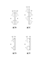
[圖2A-圖2E]分別係本發明一實施例之雷射投影系統之微透鏡陣列之局部示意圖。 [FIGS. 2A-2E] are partial schematic diagrams of the microlens array of the laser projection system according to an embodiment of the present invention.
[圖3]係本發明一實施例之掃描軌跡線之示意圖。 [Fig. 3] is a schematic diagram of the scanning trajectory of an embodiment of the present invention.
[圖4]係本發明一實施例之雷射投影系統中微透鏡陣列使用狀態示意圖。 [Fig. 4] is a schematic diagram of the state of use of the microlens array in the laser projection system according to an embodiment of the present invention.
[圖5A]係本發明一實施例之雷射投影系統中微透鏡陣列使用狀態示意圖。 [FIG. 5A] is a schematic diagram of the state of use of the microlens array in the laser projection system according to an embodiment of the present invention.
[圖5B]係圖5A所示實施例之雷射投影系統使用狀態示意圖。 [Fig. 5B] is a schematic diagram of the laser projection system in use of the embodiment shown in Fig. 5A.
[圖6]係本發明一實施例之雷射投影系統中微透鏡陣列使用狀態示意圖。 [Fig. 6] is a schematic diagram of the state of use of the microlens array in the laser projection system according to an embodiment of the present invention.
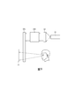
[圖7]係本發明一實施例之雷射投影系統之架構示意圖。 [Fig. 7] is a schematic diagram of the structure of a laser projection system according to an embodiment of the present invention.
[圖8]係圖7所示實施例的使用狀態示意圖。 [Fig. 8] is a schematic diagram of the use state of the embodiment shown in Fig. 7. [Fig.
[圖9]係本發明一實施例之雷射投影系統之使用狀態示意圖。 [Fig. 9] is a schematic diagram of the use state of the laser projection system according to an embodiment of the present invention.
[圖10]係本發明一實施例之穿戴式影像投射裝置的外觀示意圖。 [Fig. 10] is a schematic diagram of the appearance of a wearable image projection device according to an embodiment of the present invention.
請參閱圖1至圖4,圖1為本發明一實施例之雷射投影系統100之架構示意圖。雷射投影系統100包含雷射投影裝置11及微透鏡陣列12(以下同)。圖2A至圖2E分別為本發明一實施例之雷射投影系統100之微透鏡陣列12之局部示意圖,在此以側視的視角示意。圖3為本發明一實施例之掃描軌跡線L之示意圖。圖4為本發明一實施例之雷射投影系統100中,微透鏡陣列12使用狀態示意圖。
Please refer to FIG. 1 to FIG. 4. FIG. 1 is a schematic structural diagram of a
雷射投影裝置11具有光源,雷射投影裝置11投射光束,以
掃描的方式形成至少一掃描軌跡線L,至少一掃描軌跡線L係由複數光點P組成。也就是說,雷射投影裝置11作為影像光源,內部具有MEMS微振鏡,隨著MEMS微振鏡的擺動速度使投射的光束產生不同掃描軌跡線L,掃描軌跡線L類似正弦波的波形,或者類似利薩茹(Lissajous)曲線,如圖3所示。然而,下列圖式所繪示出的掃描軌跡線L僅為一例示,非限定本發明所述掃描軌跡線L的態樣。掃描軌跡線L上是由多個光點P所組成。
The
微透鏡陣列12設置於雷射投影裝置11的投射射程上,光束投射於微透鏡陣列12上,微透鏡陣列12包含複數個微透鏡122,微透鏡122排列分布,且微透鏡122的個數對應於光點P。在此實施例中,微透鏡122設置於一透明的基板121上(如圖2A所示),或是設置在基板121相對的二側面上(如圖2B所示)。需說明的是,如圖2A所示的實施例,投射方向A可以在基板121的一側,也可以在基板121相對的另一側上,本發明並無限制。
The
如圖2C所示,基板121的相對兩側面上皆設置有微透鏡122,位在不同側面上的微透鏡122,以相對錯開的方式排列分布,而相鄰兩者的微透鏡122之間的間隔距離W是一樣的。所述的間隔距離W指的是微透鏡122中心與另一微透鏡122中心的最短距離。此外,參考圖2D及圖2E,所述的微透鏡122可以為凸透鏡、雙凸透鏡(如圖2D所示)或是特殊設計的透鏡(如圖2E所示),換言之,微透鏡122可包含凸透鏡、雙凸透鏡、凹透鏡、雙凹透鏡、凹凸透鏡其中之一或其組合,本發明並無限定,圖式僅為例示而非為列舉。
As shown in FIG. 2C,
本發明的微透鏡122的排列方式是依據光點P的分布對應設
置,例如改變微透鏡122中相鄰二者之間的間隔距離W、微透鏡122的形狀、微透鏡122的大小及微透鏡122厚度等設置參數。所述的設置參數可以為一個以上,例如同時改變微透鏡122中相鄰二者之間的間隔距離W及微透鏡122的形狀,在一實施例中,微透鏡122的大小對應間隔距離W改變。在另一實施例中,微透鏡122厚度對應微透鏡122的大小改變。更具體的說明詳見下述。
The arrangement of the
如圖4所示,在此須說明的是,在此實施例中,掃描軌跡線L具有複數個,在橫向上串接形成類似正弦波的態樣,掃描軌跡線L上具有多個光點P,為清楚說明微透鏡122的設置與光點P的關係,僅示意局部的微透鏡122及光點P。光點P被涵蓋在微透鏡122內,掃描軌跡線L往兩端的方向D1、D2上,光點P間的距離較為密集,即光點P之間的距離逐漸縮小,然不限於此,因此微透鏡122(例如是四邊形)對應於光點P的分布狀況,微透鏡122中相鄰二者之間的間隔距離W,亦對應的自掃描軌跡線L的中央處向遠離該中央處的方向逐漸縮小、緊密。相鄰的微透鏡122之間非一定緊密排列,如圖2A至圖2E、圖4所示,相鄰的微透鏡122之間具有間隔距離W。此外,在此實施例中,微透鏡122的大小,亦自掃描軌跡線L的中央處至二端處逐漸縮小。掃描軌跡線L以類似正弦波的圖形掃描可以改善影像失真的問題。而以上圖4所示的實施例中的微透鏡陣列12的結構,則可以改善雷射投影於畫面出現暗區(光斑)的問題,整體表現可以均勻亮度,使畫面清晰呈現。
As shown in FIG. 4, it should be noted that, in this embodiment, there are a plurality of scanning trajectory lines L, which are connected in series in the lateral direction to form a sine wave-like pattern, and the scanning trajectory line L has multiple light spots. P, in order to clearly illustrate the relationship between the setting of the
在一些實施例中,類似於圖4所示的實施例,微透鏡122中相鄰二者之間的間隔距離W,自掃描軌跡線L的中央處至二端處(即以遠
離中央處的方向)逐漸縮小、緊密。然而,各微透鏡122的大小是相同的。
In some embodiments, similar to the embodiment shown in FIG. 4, the separation distance W between adjacent two in the
請參閱圖5A及圖5B,圖5A為本發明一實施例之雷射投影系統100中,微透鏡陣列12使用狀態示意圖。圖5B是圖5A所示實施例之雷射投影系統100使用狀態示意圖。與圖4所示的實施例不同的是,在此實施例中,微透鏡122中相鄰二者之間的間隔距離W,與光點P中相鄰二者之間的間距T相同。也就是說,微透鏡122排列周期與光點P的分布的周期相同,並且微透鏡122的大小是自掃描軌跡線L的中央處至二端處逐漸縮小。如圖5B所示微透鏡陣列12設置於雷射投影裝置11的投射方向上。當雷射投影裝置11的影像投射於微透鏡陣列12上時,將形成成像均勻的顯示畫面。換言之,以此微透鏡陣列12的結構,同樣可以改善雷射投影於畫面發生暗區的現象,並且兼具均勻亮度,使畫面清晰呈現的效果。
Please refer to FIGS. 5A and 5B. FIG. 5A is a schematic diagram of the use state of the
請參閱圖6,為本發明一實施例之雷射投影系統100中,微透鏡陣列12使用狀態示意圖。在此實施例中,光點P間的間距T,自掃描軌跡線L的中央處至二端處逐漸縮小;微透鏡122的排列間隔緊密,對應於光點P分布,其大小亦自掃描軌跡線L的中央處至二端處逐漸縮小,與上述實施例不同的地方在於排列的形狀,自掃描軌跡線L的中央處至二端處傾斜排列,上述關於微透鏡122的形狀,包含微透鏡122的排列形狀,圖6所示的實施例僅為一例示,本發明並不限定微透鏡122傾斜排列或旋轉排列的形狀。
Please refer to FIG. 6, which is a schematic diagram of the use state of the
綜上多個實施例,本發明並無限定微透鏡陣列12的結構,端視使用人依上述設置參數,選擇適用的微透鏡陣列12。
In summary of the above embodiments, the present invention does not limit the structure of the
在上述的實施例中,各微透鏡122以表面的法線方向觀察的
形狀為方形,然而本發明並無限定,在一些實施例中,微透鏡122的表面也可以是圓形或多邊形的形狀。
In the above-mentioned embodiment, each
請參閱圖7至圖8,圖7為本發明一實施例之雷射投影系統100之架構示意圖。圖8為圖7所示實施例的使用狀態示意圖。
Please refer to FIG. 7 to FIG. 8. FIG. 7 is a schematic diagram of the structure of a
雷射投影系統100進一步包含光學裝置13,光學裝置13設置於微透鏡陣列12的一側,包含導光元件131及光學鏡組132,在此實施例中導光元件131為一反射片。當光束經穿過微透鏡陣列12後形成實像,光學裝置13接收實像後反射至使用者眼中,使用者可在光學裝置13的一側看到虛像14。
The
請參閱圖9,為本發明一實施例之雷射投影系統100之使用狀態示意圖。雷射投影系統100包含雷射投影裝置11、微透鏡陣列12、光學鏡組132以及導光元件131。雷射投影裝置11用以產生影像,該影像是利用微機電(MEMS)之快速擺動在空間中呈現完整的畫面。微透鏡陣列12設置於雷射投影裝置11之一側,光學鏡組132設置於微透鏡陣列12之一側,導光元件131設置於光學鏡組132之一側。在此實施例中,利用雷射投影裝置11所產生之影像依序直線經過大致平行排列的微透鏡陣列12及光學鏡組132後進入導光元件131,此時使用者的眼睛可透過導光元件131看到放大之光學虛像14。依據圖9所示的實施例,可應用於一穿戴式影像投射裝置上,例如眼鏡。
Please refer to FIG. 9, which is a schematic diagram of the use state of the
請參閱圖10,為本發明一實施例之穿戴式影像投射裝置的外觀示意圖。穿戴式影像投射裝置200包含雷射投影系統100及穿戴式裝置2,穿戴式裝置2在此實施例中為眼鏡,然而並不以此為限。穿戴式裝置2
供使用者配戴使用,將雷射投影系統100設置在穿戴式裝置2上,使用者在配戴穿戴式裝置2後,可觀看到光學成像(例如是圖8或9之虛像14)。以此穿戴式影像投射裝置200,可應用在擴增實境(Augmented Reality,AR)的顯像領域上,然而,本發明並無限定穿戴式影像投射裝置200的用途。
Please refer to FIG. 10, which is a schematic diagram of the appearance of a wearable image projection device according to an embodiment of the present invention. The wearable
本發明還提出一實施例之一種改善雷射投影影像的方法,包含提供微透鏡陣列12,所述的微透鏡陣列12接收影像光源的光束投射,光束以掃描方式形成掃描軌跡線L,所述掃描軌跡線L是由複數光點P組成。關於掃描軌跡線L、光點P以及微透鏡陣列12的說明請參閱圖1至圖6以及相關段落的說明,在此不再贅述。
The present invention also proposes an embodiment of a method for improving laser projection images, including providing a
經由上述一個或多個實施例的雷射投影系統100,掃描軌跡線L可以達到投影影像無失真的效果。搭配掃描軌跡線L中光點P,微透鏡陣列12的結構設計可以改善影像光斑現象且具有使影像亮度均勻及使影像具有高清晰度的優點。
Through the
本發明還提出一實施例之一種穿戴式影像投射裝置,在穿戴式裝置上設置有雷射投影系統,同具有上述的改善影像顯示的功效。 The present invention also provides a wearable image projection device according to an embodiment, which is provided with a laser projection system on the wearable device, which also has the above-mentioned effect of improving image display.
本發明還提出一實施例之一種改善雷射投影影像的方法,藉由掃描軌跡線L及設計微透鏡陣列12的結構能夠使投射影像的產生無失真的效果,改善影像有光斑的問題,並且具有均勻光亮度、使影像清晰的效果。
The present invention also proposes an embodiment of a method for improving laser projection images. By scanning the trajectory line L and designing the structure of the
122 微透鏡 L 掃描軌跡線 P 光點 W 間隔距離 D1 方向 D2 方向 122 Micro lens L Scan the trajectory P Light spot W Separation distance D1 Direction D2 Direction
Claims (10)
Applications Claiming Priority (2)
| Application Number | Priority Date | Filing Date | Title |
|---|---|---|---|
| US201962897993P | 2019-09-09 | 2019-09-09 | |
| US62/897,993 | 2019-09-09 |
Publications (2)
| Publication Number | Publication Date |
|---|---|
| TW202111386A TW202111386A (en) | 2021-03-16 |
| TWI723660B true TWI723660B (en) | 2021-04-01 |
Family
ID=74832884
Family Applications (2)
| Application Number | Title | Priority Date | Filing Date |
|---|---|---|---|
| TW108143995A TWI723660B (en) | 2019-09-09 | 2019-12-02 | Laser projection system, wearable image projection device and method for improving laser projection image |
| TW109128521A TWI782314B (en) | 2019-09-09 | 2020-08-21 | Laser optical projection module and wearable device having the same |
Family Applications After (1)
| Application Number | Title | Priority Date | Filing Date |
|---|---|---|---|
| TW109128521A TWI782314B (en) | 2019-09-09 | 2020-08-21 | Laser optical projection module and wearable device having the same |
Country Status (3)
| Country | Link |
|---|---|
| US (1) | US11460703B2 (en) |
| CN (1) | CN112462564B (en) |
| TW (2) | TWI723660B (en) |
Families Citing this family (1)
| Publication number | Priority date | Publication date | Assignee | Title |
|---|---|---|---|---|
| CN115061290A (en) * | 2022-06-23 | 2022-09-16 | 福州京东方光电科技有限公司 | 3D display device and display system |
Citations (6)
| Publication number | Priority date | Publication date | Assignee | Title |
|---|---|---|---|---|
| TW200825615A (en) * | 2006-09-04 | 2008-06-16 | Seiko Epson Corp | Image display device |
| US20080265148A1 (en) * | 2007-04-26 | 2008-10-30 | Gibson Gregory T | Determining an operational state of a MEMS based laser scanner |
| TW201109731A (en) * | 2009-06-15 | 2011-03-16 | Fraunhofer Ges Forschung | Projection display and use thereof |
| TWI585459B (en) * | 2014-09-05 | 2017-06-01 | 英特爾股份有限公司 | An image projector and optical assembly |
| TW201903474A (en) * | 2017-06-13 | 2019-01-16 | 日商濱松赫德尼古斯股份有限公司 | Scanning display device and scanning display system |
| US20190121002A1 (en) * | 2016-09-28 | 2019-04-25 | Kohji Sakai | Microlens array, image display apparatus, object apparatus, and mold |
Family Cites Families (13)
| Publication number | Priority date | Publication date | Assignee | Title |
|---|---|---|---|---|
| JP2002236268A (en) | 2001-02-07 | 2002-08-23 | Fuji Photo Film Co Ltd | Scanning optical system and exposure device for recording image |
| JP2005017896A (en) | 2003-06-27 | 2005-01-20 | Canon Inc | Optical scanner and image forming device using the same |
| JP4158757B2 (en) | 2003-12-24 | 2008-10-01 | セイコーエプソン株式会社 | Optical display device and projection display device |
| WO2005078511A1 (en) * | 2004-02-04 | 2005-08-25 | Microvision, Inc. | Scanned-beam heads-up display and related systems and methods |
| US7791810B2 (en) * | 2007-12-21 | 2010-09-07 | Microvision, Inc. | Scanned beam display having high uniformity and diminished coherent artifacts |
| CN201293869Y (en) | 2008-08-15 | 2009-08-19 | 一品光学工业股份有限公司 | Two-slice type fTheta lens for micro-electromechanical laser scanning apparatus |
| JP2010276757A (en) * | 2009-05-27 | 2010-12-09 | Seiko Epson Corp | Projector and electro-optical device |
| US8837050B2 (en) | 2011-04-05 | 2014-09-16 | Microvision, Inc. | Optical wedge redirection apparatus and optical devices using same |
| JP6270674B2 (en) * | 2014-02-27 | 2018-01-31 | シチズン時計株式会社 | Projection device |
| JP6747769B2 (en) * | 2014-12-15 | 2020-08-26 | デクセリアルズ株式会社 | Optical element, display device, master, and method for manufacturing optical element |
| US10147235B2 (en) | 2015-12-10 | 2018-12-04 | Microsoft Technology Licensing, Llc | AR display with adjustable stereo overlap zone |
| US10025093B2 (en) | 2016-04-13 | 2018-07-17 | Microsoft Technology Licensing, Llc | Waveguide-based displays with exit pupil expander |
| CN108398791B (en) * | 2018-03-29 | 2022-11-25 | 陈超平 | Near-to-eye display device based on polarized contact lenses |
-
2019
- 2019-12-02 TW TW108143995A patent/TWI723660B/en active
-
2020
- 2020-08-21 TW TW109128521A patent/TWI782314B/en active
- 2020-08-27 US US17/004,242 patent/US11460703B2/en active Active
- 2020-08-28 CN CN202010881886.0A patent/CN112462564B/en active Active
Patent Citations (6)
| Publication number | Priority date | Publication date | Assignee | Title |
|---|---|---|---|---|
| TW200825615A (en) * | 2006-09-04 | 2008-06-16 | Seiko Epson Corp | Image display device |
| US20080265148A1 (en) * | 2007-04-26 | 2008-10-30 | Gibson Gregory T | Determining an operational state of a MEMS based laser scanner |
| TW201109731A (en) * | 2009-06-15 | 2011-03-16 | Fraunhofer Ges Forschung | Projection display and use thereof |
| TWI585459B (en) * | 2014-09-05 | 2017-06-01 | 英特爾股份有限公司 | An image projector and optical assembly |
| US20190121002A1 (en) * | 2016-09-28 | 2019-04-25 | Kohji Sakai | Microlens array, image display apparatus, object apparatus, and mold |
| TW201903474A (en) * | 2017-06-13 | 2019-01-16 | 日商濱松赫德尼古斯股份有限公司 | Scanning display device and scanning display system |
Also Published As
| Publication number | Publication date |
|---|---|
| TWI782314B (en) | 2022-11-01 |
| TW202111386A (en) | 2021-03-16 |
| CN112462564A (en) | 2021-03-09 |
| US11460703B2 (en) | 2022-10-04 |
| TW202111391A (en) | 2021-03-16 |
| US20210072546A1 (en) | 2021-03-11 |
| CN112462564B (en) | 2023-02-28 |
Similar Documents
| Publication | Publication Date | Title |
|---|---|---|
| JP6593391B2 (en) | Transmission screen and head-up display device using the same | |
| JP2021512351A (en) | Methods and systems for large field displays with scanning mirrors with refractive power | |
| JP6601742B2 (en) | Transmission screen and head-up display device using the same | |
| CN106154704B (en) | Optical element and projection device | |
| JP6645371B2 (en) | Optical device and stereoscopic display method | |
| JP2008046217A (en) | Scanning type image display device | |
| CN108269511A (en) | A kind of air suspension display system | |
| WO2016037433A1 (en) | Stereoscopic display device | |
| WO2019072032A1 (en) | Air suspension display system | |
| CN108169921B (en) | Display and display panel thereof | |
| TWI723660B (en) | Laser projection system, wearable image projection device and method for improving laser projection image | |
| CN108389531A (en) | A kind of air suspension display system | |
| TW201426014A (en) | Stereo display system | |
| WO2017068737A1 (en) | Head-up display device | |
| JPWO2017138441A1 (en) | Marker | |
| JP5682215B2 (en) | Virtual image display device | |
| CN207833880U (en) | A kind of air suspension display system | |
| JP2017032971A (en) | Microlens array and image display device | |
| JP6531899B2 (en) | Display device | |
| JP7268603B2 (en) | Image display device and display device | |
| KR20210134364A (en) | Optical waveguide units, arrays and flat lenses | |
| JP5832843B2 (en) | Autostereoscopic display | |
| CN114360367B (en) | Wearable display device | |
| JP6458924B2 (en) | Projection unit, projector | |
| JP7408537B2 (en) | Near eye light field display device |