RU81663U1 - ROLGANG - Google Patents
ROLGANG Download PDFInfo
- Publication number
- RU81663U1 RU81663U1 RU2008139574/22U RU2008139574U RU81663U1 RU 81663 U1 RU81663 U1 RU 81663U1 RU 2008139574/22 U RU2008139574/22 U RU 2008139574/22U RU 2008139574 U RU2008139574 U RU 2008139574U RU 81663 U1 RU81663 U1 RU 81663U1
- Authority
- RU
- Russia
- Prior art keywords
- roller table
- strip
- rollers
- roller
- plate
- Prior art date
Links
- 229910000906 Bronze Inorganic materials 0.000 claims abstract description 12
- 239000010974 bronze Substances 0.000 claims abstract description 12
- KUNSUQLRTQLHQQ-UHFFFAOYSA-N copper tin Chemical compound [Cu].[Sn] KUNSUQLRTQLHQQ-UHFFFAOYSA-N 0.000 claims abstract description 12
- 229910000831 Steel Inorganic materials 0.000 claims abstract description 11
- 239000010959 steel Substances 0.000 claims abstract description 11
- IZXIZTKNFFYFOF-UHFFFAOYSA-N 2-Oxazolidone Chemical compound O=C1NCCO1 IZXIZTKNFFYFOF-UHFFFAOYSA-N 0.000 claims 1
- 238000005096 rolling process Methods 0.000 abstract description 14
- 238000005098 hot rolling Methods 0.000 abstract description 7
- 239000002184 metal Substances 0.000 abstract description 6
- 238000004519 manufacturing process Methods 0.000 abstract description 2
- 230000008439 repair process Effects 0.000 description 5
- 230000005484 gravity Effects 0.000 description 2
- 238000009434 installation Methods 0.000 description 2
- 238000005272 metallurgy Methods 0.000 description 2
- 230000007704 transition Effects 0.000 description 2
- 238000004804 winding Methods 0.000 description 2
- 230000021615 conjugation Effects 0.000 description 1
- 239000000463 material Substances 0.000 description 1
Landscapes
- Metal Rolling (AREA)
Abstract
Полезная модель относится к прокатному производству, преимущественно к транспортным рольгангам непрерывных широкополосных станов горячей прокатки. Технический результат - повышение качества прокатываемых полос, увеличение выхода годного металла, сокращение аварийных простоев и повышение производительности прокатного стана. Рольганг включает участок, под которым установлено технологическое оборудование, подлежащее ремонту. Над оборудованием расположены смежные ролики с увеличенным проемом между ними, закрытым стальной проводковой плитой. На наружной поверхности проводковой плиты в прямоугольных гнездах параллельно оси рольганга установлены бронзовые вкладыши, наружные поверхности которых выступают над поверхностью проводковой плиты, а на передних участках этих поверхностей выполнены плоские наклонные скосы. 1 н.п. ф-лы; 6 илл.The utility model relates to rolling production, mainly to the transport rolls of continuous broadband hot rolling mills. The technical result - improving the quality of the rolled strips, increasing the yield of metal, reducing emergency downtime and increasing the productivity of the rolling mill. The rolling table includes a section under which the technological equipment to be repaired is installed. Above the equipment are adjacent rollers with an enlarged opening between them, covered by a steel wire plate. On the outer surface of the wiring plate, in rectangular slots parallel to the axis of the roller table, bronze inserts are installed, the outer surfaces of which protrude above the surface of the wiring plate, and flat inclined bevels are made on the front sections of these surfaces. 1 n.p. f-ly; 6 ill.
Description
Полезная модель относится к прокатному производству, преимущественно к транспортным рольгангам непрерывных широкополосных станов горячей прокатки.The utility model relates to rolling production, mainly to the transport rolls of continuous broadband hot rolling mills.
Известен рольганг для транспортировки горячекатаных полос (аналог), включающий ролики, установленные в подшипниковых опорах, закрепленных на стационарных рамах (А.А.Королев. Механическое оборудование прокатных цехов. М.: Металлургия, 1987. с.195-196, рис.V.6).The well-known roller conveyor for transporting hot-rolled strips (analogue), including rollers mounted in bearing bearings mounted on stationary frames (A.A. Korolev. Mechanical equipment of rolling shops. M .: Metallurgy, 1987. p. 195-196, Fig. V .6).
Недостатком аналога является необходимость демонтажа части роликов или роликовых секций рольганга при замене или ремонтах технологического оборудования прокатного стана, расположенного под рольгангом. Из-за большого веса, трудоемкости замены и ремонтов этого оборудования, невозможности использования стационарных цеховых мостовых кранов и необходимости применения специальных грузоподъемных средств замена или ремонт этого оборудования сопровождаются длительными простоями прокатного стана, существенными финансовыми затратами и снижением производительности стана.The disadvantage of the analogue is the need to dismantle part of the rollers or roller sections of the roller table when replacing or repairing the technological equipment of the rolling mill located under the roller table. Due to the heavy weight, the complexity of replacing and repairing this equipment, the inability to use stationary workshop bridge cranes and the need to use special lifting equipment, the replacement or repair of this equipment is accompanied by long downtimes of the rolling mill, significant financial costs and reduced productivity of the mill.
Наиболее близким техническим решением (прототипом) является рольганг, установленный над моталками горячекатаных полос, являющийся продолжением отводящего рольганга непрерывного широкополосного стана горячей прокатки (Г.Г.Фомин, А.В.Дубейковский, П.С.Гринчук. Механизация и автоматизация широкополосных станов горячей прокатки. М.: Металлургия, 1979. с.64, рис.32, поз.13; с.70, рис.39).The closest technical solution (prototype) is a roller table installed above the coilers of hot rolled strips, which is a continuation of the discharge roller table of a continuous broadband hot rolling mill (G.G. Fomin, A.V.Dubeikovsky, P.S. Grinchuk. Mechanization and automation of broadband hot mills rolling. M: Metallurgy, 1979. p. 64, fig. 32, pos. 13; p. 70, fig. 39).
В прототипе устранен недостаток аналога, связанный с необходимостью демонтажа части роликов или роликовых секций рольганга при замене или ремонтах технологического оборудования прокатного стана, установленного под рольгангом. Для этого на участке рольганга, под которым расположено технологическое оборудование, подлежащее ремонту, установлены смежные ролики с увеличенным проемом между ними. Проем между роликами при работе рольганга закрыт проводковой стальной плитой, по которой перемещается полоса при ее транспортировке по рольгангу.The prototype eliminated the lack of an analogue associated with the need to dismantle part of the rollers or roller sections of the roller table when replacing or repairing the technological equipment of the rolling mill installed under the roller table. To do this, on the roller table section, under which the technological equipment to be repaired is located, adjacent rollers are installed with an enlarged opening between them. The opening between the rollers during the operation of the roller table is closed by a wire steel plate, along which the strip moves during its transportation along the roller table.
При ремонтах технологического оборудования, установленного под рольгангом, плиту снимают и через проем между роликами выполняют демонтаж и монтаж During repairs of technological equipment installed under the roller table, the plate is removed and dismantling and installation are performed through the opening between the rollers
оборудования с помощью стационарных цеховых мостовых кранов без снятия части роликов или роликовых секций рольганга.equipment using stationary workshop bridge cranes without removing part of the rollers or roller sections of the rolling table.
Вместе с тем прототип обладает существенным недостатком, заключающимся в том, что при прохождении стальной полосы по стальной межроликовой проводковой плите из-за большого сопротивления перемещению полосы по плите, вызываемого большим коэффициентом трения между их контактирующими поверхностями, на нижней поверхности полосы образуются царапины, вмятины и другие повреждения, которые снижают качество полосы.However, the prototype has a significant drawback, namely, that when a steel strip passes through a steel inter-roller wire plate due to the high resistance to movement of the strip along the plate caused by a large coefficient of friction between their contacting surfaces, scratches, dents and other damage that reduces the quality of the strip.
Из-за большого коэффициента трения между полосой и межроликовой плитой передний торец полосы, попадая на плиту, особенно при транспортировке тонких полос, сминается или смещается в поперечном направлении относительно оси рольганга. Это приводит к сходу полосы с рольганга или при его задаче в последующий технологический агрегат, например в тянущие ролики моталки, - к заклиниванию полосы в агрегате. В результате возникают аварийные ситуации, сопровождаемые длительными простоями прокатного стана и большими потерями годного металла. В частности, при заклинивании полосы в тянущих роликах моталки и аварийной остановке непрерывного широкополосного стана горячей прокатки как минимум одна прокатываемая полоса уходит в брак.Due to the large coefficient of friction between the strip and the inter-roller plate, the front end of the strip, getting on the plate, especially when transporting thin strips, is crushed or shifted in the transverse direction relative to the axis of the roller table. This leads to the descent of the strip from the roller table or, when it is assigned to a subsequent technological unit, for example, to pulling winder rollers, to jam the strip in the unit. As a result, emergency situations occur, accompanied by long downtimes of the rolling mill and large losses of suitable metal. In particular, when the strip is jammed in the pulling rollers of the coiler and the emergency stop of the continuous broadband hot rolling mill, at least one strip rolled goes into marriage.
Техническим результатом полезной модели является повышение качества прокатываемых полос, снижение потерь металла в брак, увеличение выхода годного металла, сокращение аварийных простоев и повышение производительности прокатного стана.The technical result of the utility model is to improve the quality of rolled strips, reduce metal loss in marriage, increase yield of metal, reduce downtime and increase productivity of the rolling mill.
Технический результат достигается тем, что на участке рольганга, под которым расположено технологическое оборудование, подлежащее ремонту, установлены смежные ролики с увеличенным проемом между ними, который при работе рольганга закрыт проводковой стальной плитой, по которой перемещается полоса при ее транспортировке по рольгангу. На наружной поверхности плиты параллельно оси рольганга выполнены поперечные прямоугольные гнезда, в которых закреплены сменные бронзовые вкладыши, наружные поверхности которых выступают над поверхностью проводковой плиты, а на передних участках наружных поверхностей вкладышей с уклоном в сторону входа на них полосы выполнены плоские наклонные скосы.The technical result is achieved by the fact that on the roller table section, under which the technological equipment to be repaired is located, adjacent rollers are installed with an enlarged opening between them, which during operation of the roller table is closed by a wire steel plate, along which the strip moves during its transportation along the roller table. On the outer surface of the plate parallel to the axis of the roller table, transverse rectangular nests are made in which removable bronze bushings are fixed, the outer surfaces of which protrude above the surface of the wiring plate, and flat inclined bevels are made on the front sections of the outer surfaces of the liners with a slope towards the entrance to them.
Сущность технического решения поясняется на примере участка рольганга непрерывного широкополосного стана горячей прокатки 2000, расположенного между первой и второй группой моталок, предназначенных для смотки в рулоны соответственно тонких и толстых горячекатаных полос.The essence of the technical solution is illustrated by the example of the roller conveyor section of a continuous wide-band hot rolling mill 2000 located between the first and second group of coilers intended for winding coils of thin and thick hot-rolled strips, respectively.
Полезная модель поясняется чертежами, на которых изображены:The utility model is illustrated by drawings, which depict:
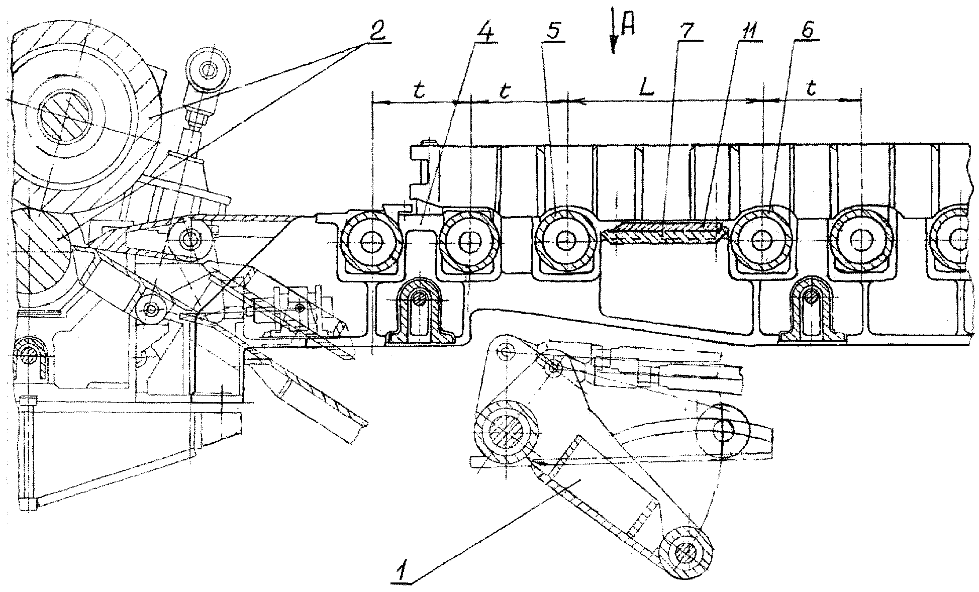
Фиг.1. Участок рольганга с увеличенным проемом между смежными роликами.Figure 1. A section of the roller table with an enlarged opening between adjacent rollers.
Фиг.2. Вид на рольганг по стрелке А на фиг.1.Figure 2. View of the roller table in arrow A in figure 1.
Фиг.3. Стальная поводковая плита в сборе с бронзовыми вкладышами - боковой вид по стрелке Г на фиг.4.Figure 3. Steel lead plate assembly with bronze liners - side view along arrow G in figure 4.
Фиг.4. Вид на поводковую плиту по стрелке Б на фиг.3.Figure 4. View of the leash plate in arrow B in figure 3.
Фиг.5. Разрез проводковой плиты по линии В-В на фиг.4.Figure 5. The section of the wiring plate along the line BB in figure 4.
Фиг.6. Схема перехода полосы с ролика на бронзовые вкладыши.6. Scheme of transition of a strip from a roller to bronze inserts.
Рольганг включает участок с роликами, под которым расположено технологическое оборудование, подлежащее ремонту, в рассматриваемом случае - оборудование узла верхней проводки 1 и других узлов моталки (условно не показаны), через которые прокатанная полоса подается на смотку от тянущих роликов с индивидуальным приводом от электродвигателей 3. Ролики установлены в подшипниковых опорах, закрепленных болтами на продольных опорных балках 4, опирающихся на фундамент.The rollgang includes a section with rollers, under which there is technological equipment to be repaired, in this case, the equipment of the top wiring unit 1 and other winder units (not shown conditionally) through which the rolled strip is fed to the winding from the pulling rollers with an individual drive from electric motors 3 The rollers are installed in bearing bearings, bolted to the longitudinal support beams 4, based on the foundation.
Участок рольганга, под которым установлено технологическое оборудование, содержит смежные ролики 5 и 6 с увеличенным по сравнению с другими роликами проемом между ними.The roller table section, under which the technological equipment is installed, contains adjacent rollers 5 and 6 with a larger opening between them compared to other rollers.
Расстояние L между осями смежных роликов 5 и 6 больше постоянного шага t других роликов рольганга на величину необходимую для прохода через проем между роликами демонтируемого и монтируемого технологического оборудования, расположенного под рассматриваемым участком рольганга.The distance L between the axes of adjacent rollers 5 and 6 is greater than the constant step t of the other rollers of the roller table by the amount necessary to pass through the opening between the rollers of the dismountable and mounted technological equipment located under the section of the roller table under consideration.
Проем между роликами 5 и 6 закрыт проводковой стальной плитой 7, на наружной поверхности которой параллельно оси 8 рольганга выполнены поперечные прямоугольные гнезда 9, в которых с помощью болтов 10 с потайными головками закреплены сменные бронзовые вкладыши 11.The opening between the rollers 5 and 6 is closed by a steel wire plate 7, on the outer surface of which parallel to the axis 8 of the roller table there are transverse rectangular sockets 9, in which replaceable bronze inserts 11 are fixed using bolts 10 with countersunk heads.
Наружные горизонтальные поверхности вкладышей выступают над поверхностью проводковой плиты 7 на величину β (фиг.3). Плита закреплена заплечиками 12 на продольных опорных балках 4. На передних участках наружных поверхностей вкладышей 11 с уклоном в сторону входа на них полосы выполнены плоские наклонные скосы 13.The outer horizontal surfaces of the liners protrude above the surface of the wiring plate 7 by a value of β (figure 3). The plate is fixed by shoulders 12 on the longitudinal support beams 4. On the front sections of the outer surfaces of the liners 11 with a slope towards the entrance to the strip they made flat inclined bevels 13.
При транспортировке полосы 14 по рольгангу и ее передаче от ролика 5 к ролику 6 передний конец полосы после схода с ролика 5 под действием силы тяжести сначала попадает на плоские наклонные скосы 13 бронзовых вкладышей 11 (положение I переднего конца полосы на фиг.6). При дальнейшем движении по скосам в момент перехода конца полосы через линию сопряжения скосов с наружной горизонтальной When transporting the strip 14 along the rolling table and transferring it from the roller 5 to the roller 6, the front end of the strip after leaving the roller 5 under the action of gravity first falls on flat inclined bevels 13 of the bronze inserts 11 (position I of the front end of the strip in Fig.6). With further movement along the bevels at the moment of transition of the end of the strip through the line of conjugation of the bevels with the horizontal
поверхностью вкладышей под действием вертикальной составляющей силы инерции, возникающей при перемещении конца полосы по скосам, происходит отрыв конца полосы от наружных горизонтальных поверхностей вкладышей. После отрыва некоторое время передний конец и часть полосы перемещаются над горизонтальной поверхностью вкладышей, ее не касаясь, после чего под действием силы тяжести конец полосы опускается на эту поверхность (положение II на фиг.6), и дальнейшее движение полосы до смежного ролика 6 происходит по горизонтальным поверхностям бронзовых вкладышей 11.the surface of the liners under the action of the vertical component of the inertia that occurs when the end of the strip moves along the bevels, the end of the strip is torn off from the outer horizontal surfaces of the liners. After tearing off for some time, the front end and part of the strip move over the horizontal surface of the liners without touching it, after which, under the action of gravity, the end of the strip falls to this surface (position II in FIG. 6), and the further movement of the strip to the adjacent roller 6 occurs along horizontal surfaces of bronze inserts 11.
При ремонтах технологического оборудования, установленного на рассматриваемом участке рольганга под смежными роликами 5 и 6, межроликовую проводковую плиту 7 снимают и через проем между роликами с помощью цеховых мостовых кранов выполняют операции по демонтажу и монтажу ремонтируемого оборудования.When repairing technological equipment installed on the considered section of the roller table under adjacent rollers 5 and 6, the inter-roller wire plate 7 is removed and through the opening between the rollers using workshop bridge cranes dismantle and assemble the equipment being repaired.
Благодаря расположению наружных горизонтальных поверхностей бронзовых вкладышей выше наружной поверхности стальной проводковой плиты на величину 5, перемещение полосы происходит только по вкладышам без касания с поверхностью проводковой плиты. Из-за низкого коэффициента трения между контактирующими поверхностями транспортируемой стальной полосы и бронзовых вкладышей сопротивление перемещению полосы по вкладышам существенно уменьшается.Due to the location of the outer horizontal surfaces of the bronze liners above the outer surface of the steel wire plate by a value of 5, the movement of the strip occurs only along the liners without touching the surface of the wire plate. Due to the low coefficient of friction between the contacting surfaces of the transported steel strip and the bronze liners, the resistance to movement of the strip along the liners is significantly reduced.
Применение скосов 13 на передних участках вкладышей уменьшает путь прохождения передним концом и частью полосы между роликами 5 и 6, а при повышенных скоростях транспортировки полосы передний конец полосы после прохождения скосов 13 сразу поступает на ролик 6, не касаясь вкладышей. Благодаря этому, а также меньшей твердости материала вкладышей по сравнению твердостью стальной полосы, на поверхности полосы, контактирующей с вкладышами, исключаются царапины, вмятины и другие повреждения, что повышает качество прокатываемых полос, снижает потери металла в брак и увеличивает выход годного металла. Устраняются схождения полосы с рольганга и заклинивания полосы при ее задаче в последующий технологический агрегат, благодаря чему исключаются аварийные ситуации, сопровождаемые длительными простоями прокатного стана, и повышается его производительность.The use of bevels 13 in the front sections of the liners reduces the path for the front end and part of the strip between the rollers 5 and 6, and at increased speeds for transporting the strip, the front end of the strip after passing the bevels 13 immediately enters the roller 6 without touching the liners. Due to this, as well as lower hardness of the material of the liners compared to the hardness of the steel strip, scratches, dents and other damage are eliminated on the surface of the strip in contact with the liners, which improves the quality of the rolled strips, reduces metal loss in marriage and increases the yield of metal. Convergence of the strip from the roller table and jamming of the strip during its task in the subsequent technological unit are eliminated, which eliminates emergency situations accompanied by long downtimes of the rolling mill, and increases its productivity.
Через рассматриваемый участок рольганга с роликами 5 и 6 на непрерывном широкополосном стане 2000 горячей прокатки ОАО "Северсталь" при раскрытых тянущих роликах 2 на вторую группу моталок подаются горячекатаные полосы увеличенной толщины. Благодаря применению проводковой плиты 7 с бронзовыми Through the considered section of the roller table with rollers 5 and 6 on the continuous wide-band hot rolling mill 2000 of Severstal, with the pulling rollers 2 open, hot-rolled strips of increased thickness are fed to the second group of winders. Through the use of wire plate 7 with bronze
вкладышами 11, на этом стане 2000 были получены все указанные положительные результаты применения рольганга по предлагаемому изобретению. Следует также отметить, что, благодаря отсутствию необходимости демонтажа и монтажа роликов рольганга при ремонтах, применение такого рольганга позволяет существенно сократить продолжительность плановых ремонтов оборудования непрерывных широкополосных станов горячей прокатки и повысить их производительность.inserts 11, on this mill 2000 were obtained all these positive results of the use of the roller table according to the invention. It should also be noted that, due to the absence of the need for dismantling and installation of the roller table rollers during repairs, the use of such a roller table can significantly reduce the duration of scheduled repairs of equipment of continuous broadband hot rolling mills and increase their productivity.
При эксплуатации бронзовые вкладыши 11 периодически заменяют на новые, что не требует замены проводковых плит 7 и также сокращает продолжительность и затраты на ремонты оборудования.During operation, the bronze inserts 11 are periodically replaced with new ones, which does not require replacement of the wiring plates 7 and also reduces the duration and cost of equipment repairs.
Таким образом, предлагаемое техническое решение по изобретению обеспечивает достижение поставленной цели и рекомендуется к широкому внедрению на практике.Thus, the proposed technical solution according to the invention ensures the achievement of the goal and is recommended for widespread implementation in practice.
Claims (1)
Priority Applications (1)
| Application Number | Priority Date | Filing Date | Title |
|---|---|---|---|
| RU2008139574/22U RU81663U1 (en) | 2008-10-06 | 2008-10-06 | ROLGANG |
Applications Claiming Priority (1)
| Application Number | Priority Date | Filing Date | Title |
|---|---|---|---|
| RU2008139574/22U RU81663U1 (en) | 2008-10-06 | 2008-10-06 | ROLGANG |
Publications (1)
| Publication Number | Publication Date |
|---|---|
| RU81663U1 true RU81663U1 (en) | 2009-03-27 |
Family
ID=40543196
Family Applications (1)
| Application Number | Title | Priority Date | Filing Date |
|---|---|---|---|
| RU2008139574/22U RU81663U1 (en) | 2008-10-06 | 2008-10-06 | ROLGANG |
Country Status (1)
| Country | Link |
|---|---|
| RU (1) | RU81663U1 (en) |
Cited By (1)
| Publication number | Priority date | Publication date | Assignee | Title |
|---|---|---|---|---|
| RU2602918C2 (en) * | 2011-06-22 | 2016-11-20 | Прайметалз Текнолоджиз Аустриа ГмбХ | Device for replacement of pulling rollers driven rolling mill |
-
2008
- 2008-10-06 RU RU2008139574/22U patent/RU81663U1/en active
Cited By (1)
| Publication number | Priority date | Publication date | Assignee | Title |
|---|---|---|---|---|
| RU2602918C2 (en) * | 2011-06-22 | 2016-11-20 | Прайметалз Текнолоджиз Аустриа ГмбХ | Device for replacement of pulling rollers driven rolling mill |
Similar Documents
| Publication | Publication Date | Title |
|---|---|---|
| KR101099868B1 (en) | Method for increasing the production range of metal products rolling equipment and equipment for the method | |
| CN103890216B (en) | Magnesium rolling mill | |
| RU81663U1 (en) | ROLGANG | |
| CN202411151U (en) | A high-speed cold rolling and recoiling production line with a leveler | |
| KR102241344B1 (en) | A rolling mill edger | |
| EP0721812A1 (en) | Strip side-guides | |
| CN116060459B (en) | Metal belt guiding device, metal belt production line and metal belt production method | |
| CN216827989U (en) | Uncoiling leveling device | |
| CN111229843A (en) | Bridge for production of large-sized bar and method of using the same | |
| CN211613876U (en) | Metal plate coiling and deviation correcting device | |
| KR101193787B1 (en) | Stripper for the Mill | |
| Kozhevnikov et al. | IMPROVEMENT OF OPERATIONAL EFFICIENCY OF COLD ROLLING MILL WORK ROLLS. | |
| CN116727484B (en) | A winding and clamping device to prevent steel from sticking | |
| CN119566071B (en) | A method for preventing edge quality defects in hot-rolled strip steel | |
| JP6922668B2 (en) | Hot rolling method and hot rolling machine line | |
| Yergaliyev et al. | Study of stress-strain state of the roller conveyor | |
| CN213968322U (en) | Device for preventing outlet strip of finishing mill from being buckled down | |
| RU69427U1 (en) | HANDLING MANIPULATOR | |
| RU2183524C1 (en) | Uncoiler for shape bending aggregate | |
| RU2283711C2 (en) | Hot rolled strip coil conveyer | |
| SU1748896A1 (en) | Sheet rolling mill delivery roller table | |
| RU2254953C1 (en) | Drawing apparatus of shape bending mill | |
| JP6645336B2 (en) | How to operate the crop conveyor | |
| KR101536458B1 (en) | Apparatus and Method for manufacturing of strip | |
| CN209613810U (en) | A kind of I frame entrance memorial archway torsional oscillation buffer unit of rougher of hot strip mill |