RU57189U1 - TURNING WOODWORKING MACHINE - Google Patents
TURNING WOODWORKING MACHINE Download PDFInfo
- Publication number
- RU57189U1 RU57189U1 RU2006114281/22U RU2006114281U RU57189U1 RU 57189 U1 RU57189 U1 RU 57189U1 RU 2006114281/22 U RU2006114281/22 U RU 2006114281/22U RU 2006114281 U RU2006114281 U RU 2006114281U RU 57189 U1 RU57189 U1 RU 57189U1
- Authority
- RU
- Russia
- Prior art keywords
- headstock
- bed
- spindle
- faceplate
- tool holder
- Prior art date
Links
Abstract
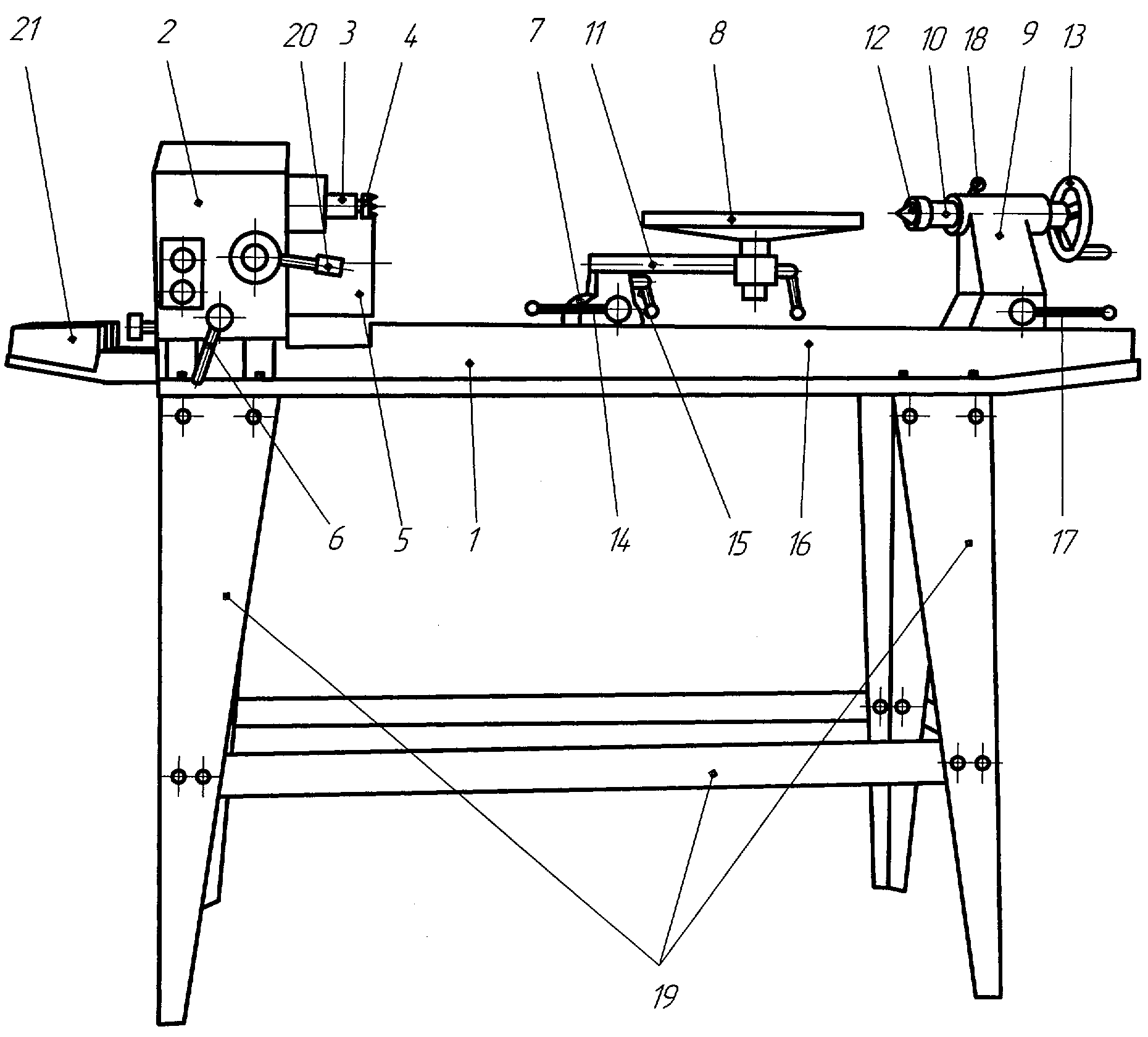
Полезная модель относится к области станкостроения, в частности к токарным деревообрабатывающим станкам. Токарный деревообрабатывающий станок содержит станину 1 с установленной на ней передней бабкой 2, снабженной шпинделем 3, в котором может крепиться планшайба или центр 4 передней бабки с зубцами. Шпиндель 3 кинематически связан с валом электродвигателя 5 через вариатор. Электродвигатель 5 с передней бабкой 2 установлены на станине 1 с возможностью регулируемого фиксируемого разворота в горизонтальной плоскости на 180°. Передняя бабка 2 имеет пять основных позиций: позиция 0° - при всех работах с использованием шпинделя и задней бабки, позиция 60°/190°/120° - при работах с использованием планшайбы, позиция 180° - при работах с использованием планшайбы и применением удлинителя станины. Для изменения скорости шпинделя передней бабки поворачивают ручку 20 регулирования частоты вращения шпинделя передней бабки на нужную установку по шкале скоростей (станок имеет десять фиксированных скоростей). При этом изменение скорости шпинделя должно осуществляться только при работающем электродвигателе. Станина 1 станка снабжена съемным удлинителем 21, на который может быть переустановлена опора 7 резцедержателя 8 с кронштейном 10, когда передняя бабка 2 развернута на 180° и выполняется обработка детали, закрепленной на планшайбе. Если это не требуется, то удлинитель 21 станины 1 не устанавливается. Использование заявляемой полезной модели существенно расширяет функциональные возможности токарного деревообрабатывающего станка, а также повышает его безопасность и удобство в его работе. 5 З.П. Ф-ЛЫ, 1 ИЛ.The utility model relates to the field of machine tools, in particular to turning woodworking machines. The woodworking lathe includes a bed 1 with a headstock 2 mounted on it, equipped with a spindle 3, in which a faceplate or center 4 of the front headstock with teeth can be attached. The spindle 3 is kinematically connected to the shaft of the electric motor 5 through a variator. An electric motor 5 with a front headstock 2 is mounted on a bed 1 with the possibility of an adjustable fixed turn in a horizontal plane through 180 °. The headstock 2 has five main positions: position 0 ° for all operations using the spindle and tailstock, position 60 ° / 190 ° / 120 ° for operations using the faceplate, position 180 ° for operations using the faceplate and extension beds. To change the spindle speed of the headstock, turn the knob 20 to control the spindle speed of the headstock to the desired setting on the speed scale (the machine has ten fixed speeds). In this case, the spindle speed should be changed only when the motor is running. The bed 1 of the machine is equipped with a removable extension 21, on which the support 7 of the tool holder 8 with the bracket 10 can be reinstalled, when the headstock 2 is rotated 180 ° and the part mounted on the faceplate is processed. If this is not required, then the extension 21 of the frame 1 is not installed. The use of the claimed utility model significantly expands the functionality of a turning woodworking machine, and also increases its safety and convenience in its operation. 5 C.P. F-LY, 1 IL.
Description
Полезная модель относится к области станкостроения, в частности к токарным деревообрабатывающим станкам, и может быть использована для токарной обработки деталей из дерева.The utility model relates to the field of machine tools, in particular to turning woodworking machines, and can be used for turning parts from wood.
Известен и выбран в качестве прототипа токарный деревообрабатывающий станок, содержащий станину, электродвигатель с кинематически связанной с ним передней (шпиндельной) бабкой со ступенчатым регулированием числа оборотов шпинделя, а также заднюю бабку и резцедержатель [А.с. СССР №1787768, МПК В 27 С 7/00, 1993 г.].Known and selected as a prototype is a woodworking lathe containing a bed, an electric motor with a kinematically connected front (spindle) headstock with step-by-step adjustment of the spindle speed, as well as a tailstock and tool holder [A.S. USSR No. 1787768, IPC В 27 С 7/00, 1993].
Недостатками известного токарного деревообрабатывающего станка являются ограниченные функциональные возможности (нельзя изменять ось вращения заготовки относительно станины), а также трудоемкость ступенчатого регулирования числа оборотов вращения шпинделя (необходимы отключение электродвигателя и переустановка ремня на ступенчатых шкивах).The disadvantages of the known woodworking lathe are limited functionality (you cannot change the axis of rotation of the workpiece relative to the bed), as well as the complexity of the step-by-step regulation of the number of revolutions of rotation of the spindle (it is necessary to turn off the motor and reinstall the belt on the step pulleys).
Задачей заявляемой полезной модели является устранение указанных недостатков.The objective of the claimed utility model is to remedy these disadvantages.
Поставленная задача достигается тем, что в токарном деревообрабатывающем станке, содержащем станину, переднюю бабку со шпинделем для крепления центра передней бабки с зубцами или планшайбы, кинематически связанным с электродвигателем через ременную передачу, а также установленные в пазу станины заднюю бабку и резцедержатель, согласно полезной модели, передняя бабка с электродвигателем шарнирно установлены на станине с возможностью поворота в горизонтальной плоскости до 180° и фиксации в заданных промежуточных и крайних положениях, при этом резцедержатель установлен на съемном вращающемся кронштейне, а передняя бабка выполнена с плавным фиксируемым регулированием числа оборотов шпинделя.The problem is achieved in that in a turning woodworking machine containing a bed, a headstock with a spindle for fastening the center of the headstock with teeth or faceplates kinematically connected to the electric motor via a belt drive, as well as a tailstock and a tool holder installed in the groove of the bed, according to the utility model , the headstock with an electric motor is pivotally mounted on the bed with the possibility of rotation in a horizontal plane up to 180 ° and fixing in predetermined intermediate and extreme positions, etc. This tool holder is mounted on a removable rotating bracket, and the headstock is provided with a smooth lockable adjusting spindle speed.
Для установки резцедержателя перед развернутой на 180° передней бабкой (при обработке торцовой поверхности закрепленной на планшайбе заготовки) станок снабжен удлинителем станины.To install the tool holder in front of the headstock deployed 180 ° (when machining the end surface of the workpiece fixed to the faceplate), the machine is equipped with a bed extension.
Для облегчения конструкции токарного деревообрабатывающего станка его станина установлена на собранной из тонкостенных профилей опоре конструкции.To facilitate the design of a woodworking lathe, its bed is mounted on a structural support assembled from thin-walled profiles.
Полезная модель иллюстрирована чертежом, на котором схематично представлен общий вид заявляемого токарного деревообрабатывающего станка.The utility model is illustrated in the drawing, which schematically shows a General view of the inventive turning woodworking machine.
Перечень позиций на чертежеThe list of items in the drawing
1 - станина;1 - bed;
2 - передняя бабка;2 - front headstock;
3 - шпиндель передней бабки;3 - spindle of the front headstock;
4 - центр передней бабки с зубцами;4 - the center of the front headstock with teeth;
5 - электродвигатель;5 - electric motor;
6 - ручка фиксации положения передней бабки;6 - handle fixing the position of the headstock;
7 - опора резцедержателя;7 - support tool holder;
8 - резцедержатель;8 - tool holder;
9 - задняя бабка;9 - tailstock;
10 - пиноль задней бабки;10 - the tailstock tailstock;
11 - вращающийся кронштейн резцедержателя;11 - rotating bracket of the tool holder;
12 - центр задней бабки;12 - the center of the tailstock;
13 - маховик осевого перемещения пиноли;13 - flywheel axial movement of the pin;
14 - ручка фиксации опоры резцедержателя;14 - handle for fixing the support of the tool holder;
15 - ручка фиксации кронштейна резцедержателя;15 - handle for fixing the tool holder bracket;
16 - ручка фиксации резцедержателя;16 - handle for fixing the tool holder;
17 - ручка фиксации положения задней бабки;17 - handle fixing the position of the tailstock;
18 - ручка фиксации пиноли задней бабки;18 - handle fixing pintles of the tailstock;
19 - опора станины;19 - bed support;
20 - ручка регулирования частоты вращения шпинделя передней бабки;20 - knob for controlling the spindle speed of the headstock;
21 - удлинитель станины.21 - bed extension.
Токарный деревообрабатывающий станок содержит станину 1 с установленной на ней передней бабкой 2, снабженной шпинделем 3, в котором может крепиться планшайба или центр 4 передней бабки с зубцами. Шпиндель 3 кинематически связан через вариатор с валом электродвигателя 5. Электродвигатель с передней бабкой 2 установлены на станине 1 с возможностью регулируемого фиксируемого разворота в горизонтальной плоскости на 180°. Передняя бабка 2 имеет пять основных позиций: позиция 0° - при всех работах с использованием The woodworking lathe includes a bed 1 with a headstock 2 mounted on it, equipped with a spindle 3, in which a faceplate or center 4 of the front headstock with teeth can be attached. The spindle 3 is kinematically connected via a variator to the shaft of the electric motor 5. The electric motor with the headstock 2 are mounted on the bed 1 with the possibility of an adjustable fixed turn in the horizontal plane through 180 °. The headstock 2 has five main positions: position 0 ° - for all operations using
шпинделя и задней бабки, позиция 60°/90°/120° - при работах с использованием планшайбы, позиция 180° - при работах с использованием планшайбы и применением удлинителя станины. Для обеспечения контролируемого положения передней бабки 2 она снабжена ручкой 6 фиксации. В станине 1 выполнен паз, в котором с возможностью продольного перемещения установлены опора 7 резцедержателя 8 и задняя бабка 9. Резцедержатель 8 установлен на вращающемся кронштейне 10. Кронштейн 10 выполнен съемным, и резцедержатель 8 может быть переустановлен в опору 7. Задняя бабка 9 имеет пиноль 11, в которой установлен центр 12 задней бабки, снабженный хвостовиком в виде конуса, а также маховик 13 осевого перемещения пиноли. Фиксация положения опоры резцедержателя осуществляется ручкой 14, кронштейна 10 - ручкой 15, резцедержателя - ручкой 16, задней бабки - ручкой 17, пиноли - ручкой 18.spindle and tailstock, position 60 ° / 90 ° / 120 ° - when working using the faceplate, position 180 ° - when working using the faceplate and using a bed extension. To ensure a controlled position of the headstock 2, it is equipped with a handle 6 fixation. In the frame 1, a groove is made in which the support 7 of the tool holder 8 and the tailstock 9 are mounted with the possibility of longitudinal movement. The tool holder 8 is mounted on the rotating bracket 10. The bracket 10 is removable and the tool holder 8 can be reinstalled in the support 7. The tailstock 9 has a pin 11, in which the center of the tailstock 12 is installed, provided with a shank in the form of a cone, as well as a flywheel 13 of axial movement of the quill. The position of the tool holder support is fixed by the handle 14, the bracket 10 - by the handle 15, the tool holder - by the handle 16, the tailstock - by the handle 17, the pins - by the handle 18.
Подготовка токарного деревообрабатывающего станка к работе осуществляется следующим образом.Preparation of a woodworking lathe for work is as follows.
Предварительно собранный станок устанавливают на несущую опору 19, выполненную из тонкостенных профилей. Центр передней бабки 2 и центр задней бабки 8 имеют конус. Для их установки вставляют конуса в ответные конические отверстия передней и задней бабок твердым сильным движением. Они будут далее закреплены, когда заготовку вставят между центрами.The preassembled machine is mounted on a supporting support 19 made of thin-walled profiles. The center of the headstock 2 and the center of the tailstock 8 have a cone. To install them, insert the cone into the mating conical openings of the front and rear headstock with a solid strong movement. They will be further fixed when the workpiece is inserted between the centers.
Для изменения скорости шпинделя передней бабки поворачивают ручку 20 регулирования частоты вращения шпинделя передней бабки на нужную установку по шкале скоростей (станок имеет десять фиксированных скоростей). При этом изменение скорости шпинделя должно осуществляться только при работающем электродвигателе.To change the spindle speed of the headstock, turn the knob 20 to control the spindle speed of the headstock to the desired setting on the speed scale (the machine has ten fixed speeds). In this case, the spindle speed should be changed only when the motor is running.
Перед выключением станка необходимо перевести ручку 20 на минимальную скорость. Станина 1 станка снабжена съемным удлинителем 21, на который может быть переустановлена опора 7 резцедержателя 8 с кронштейном 10, когда передняя бабка 2 развернута на 180° и выполняется обработка детали, закрепленной на планшайбе. Если это не требуется, то удлинитель 21 станины 1 не устанавливается.Before turning off the machine, turn knob 20 to minimum speed. The bed 1 of the machine is equipped with a removable extension 21, on which the support 7 of the tool holder 8 with the bracket 10 can be reinstalled, when the headstock 2 is rotated 180 ° and the part mounted on the faceplate is processed. If this is not required, then the extension 21 of the frame 1 is not installed.
Токарная обработка заготовки в центрах осуществляется традиционным способом с использованием известных ручных токарных резцов по дереву.Turning of the workpiece in the centers is carried out in the traditional way using well-known manual wood turning tools.
При обработке закрепленной на планшайбе заготовки заявляемая конструкция токарного станка позволяет расширить его функциональные возможности путем регулируемого изменения угла оси вращения заготовки относительно станины. Так, при установке передней бабки 2 под углом 90° можно обрабатывать заготовки большого диаметра (заготовка находится сбоку от станины 1 и не задевает ее). При установке под углом 180° станина 1 не препятствует свободному доступу токарю к обрабатываемой заготовке, что повышает удобство и безопасность работы. Установка передней бабки 2 в промежуточных положениях 60° и 120° также позволяет обрабатывать заготовки большого диаметра (например, делать внутреннюю выборку в таких деталях, как чаша, кубышка и т.п.).When processing a workpiece mounted on the faceplate, the claimed design of the lathe allows you to expand its functionality by adjustable changes in the angle of rotation of the workpiece relative to the bed. So, when installing the headstock 2 at an angle of 90 °, you can process large diameter workpieces (the workpiece is located on the side of the bed 1 and does not touch it). When installed at an angle of 180 °, the bed 1 does not interfere with the free access of the turner to the workpiece, which increases the convenience and safety of work. The installation of the headstock 2 in intermediate positions 60 ° and 120 ° also allows you to process large diameter workpieces (for example, to make internal sampling in details such as a bowl, egg cup, etc.).
Использование заявляемой полезной модели существенно расширяет функциональные возможности токарного деревообрабатывающего станка, а также повышает его безопасность и удобство в его работе.The use of the claimed utility model significantly expands the functionality of a turning woodworking machine, and also increases its safety and convenience in its operation.
Claims (5)
Priority Applications (1)
| Application Number | Priority Date | Filing Date | Title |
|---|---|---|---|
| RU2006114281/22U RU57189U1 (en) | 2006-04-27 | 2006-04-27 | TURNING WOODWORKING MACHINE |
Applications Claiming Priority (1)
| Application Number | Priority Date | Filing Date | Title |
|---|---|---|---|
| RU2006114281/22U RU57189U1 (en) | 2006-04-27 | 2006-04-27 | TURNING WOODWORKING MACHINE |
Publications (1)
| Publication Number | Publication Date |
|---|---|
| RU57189U1 true RU57189U1 (en) | 2006-10-10 |
Family
ID=37435926
Family Applications (1)
| Application Number | Title | Priority Date | Filing Date |
|---|---|---|---|
| RU2006114281/22U RU57189U1 (en) | 2006-04-27 | 2006-04-27 | TURNING WOODWORKING MACHINE |
Country Status (1)
| Country | Link |
|---|---|
| RU (1) | RU57189U1 (en) |
Cited By (1)
| Publication number | Priority date | Publication date | Assignee | Title |
|---|---|---|---|---|
| RU2699605C1 (en) * | 2019-02-01 | 2019-09-06 | Федеральное государственное бюджетное образовательное учреждение высшего образования "Кубанский государственный аграрный университет имени И.Т. Трубилина" | Device for facing of cylindrical parts on lathe |
-
2006
- 2006-04-27 RU RU2006114281/22U patent/RU57189U1/en not_active IP Right Cessation
Cited By (1)
| Publication number | Priority date | Publication date | Assignee | Title |
|---|---|---|---|---|
| RU2699605C1 (en) * | 2019-02-01 | 2019-09-06 | Федеральное государственное бюджетное образовательное учреждение высшего образования "Кубанский государственный аграрный университет имени И.Т. Трубилина" | Device for facing of cylindrical parts on lathe |
Similar Documents
| Publication | Publication Date | Title |
|---|---|---|
| CN110253296A (en) | A kind of brill milling integral type multi-process numeric control drilling machine tool | |
| RU57189U1 (en) | TURNING WOODWORKING MACHINE | |
| KR101811168B1 (en) | Tool mounting portion, tool holder for machine tool provided with said tool mounting portion, and machine tool | |
| CN105458805A (en) | Disc type tool changer system of horizontal numerical-control boring and milling machine | |
| CN208556003U (en) | A kind of top fixture of rotary multifunctional | |
| US20070204464A1 (en) | Jewelry making machine with improved cutting capabilities and methods of use thereof | |
| CN204036104U (en) | The disc type tool magazine system of horizontal digital-control boring-milling machine | |
| CN210756340U (en) | Numerical control drilling, tapping and milling integrated processing equipment with central through hole water outlet | |
| US5333657A (en) | Workpiece turing and milling apparatus | |
| CN209477319U (en) | It is a kind of for processing the numerically controlled lathe of steel watchcase | |
| CN208772505U (en) | A kind of Manual drilling machine | |
| CN208945249U (en) | A kind of milling machine | |
| CN107931742B (en) | Gear machining equipment | |
| JP2000218422A (en) | Machine tool and operation method thereof | |
| CN206643705U (en) | A kind of high-precision cutter sharpener | |
| CN216126916U (en) | Machining tool for reamer production | |
| CN113857920A (en) | Portable large-diameter circular steel tube turning special device | |
| CN105328492A (en) | Main transmission system of horizontal numerical control boring and milling machine | |
| RU57190U1 (en) | TURNING WOODWORKING MACHINE | |
| CN208303898U (en) | Beveler | |
| CN208773115U (en) | A kind of brake disc Milling Machine | |
| CN215698004U (en) | Precision bearing inner race outer ball groove processingequipment | |
| CN215698308U (en) | Fastening device based on adjustable supporting angle for horizontal milling machine | |
| CN219542360U (en) | End face milling machine with adjustable working bar | |
| CN216576825U (en) | End face milling machine |
Legal Events
| Date | Code | Title | Description |
|---|---|---|---|
| MM1K | Utility model has become invalid (non-payment of fees) |
Effective date: 20120428 |