RU55790U1 - COMPLEX FOR VIBRODOWNING OF FOUNDATIONS OF CONTACT NETWORK SUPPORTS AND ANCHORS - Google Patents
COMPLEX FOR VIBRODOWNING OF FOUNDATIONS OF CONTACT NETWORK SUPPORTS AND ANCHORS Download PDFInfo
- Publication number
- RU55790U1 RU55790U1 RU2006118992/22U RU2006118992U RU55790U1 RU 55790 U1 RU55790 U1 RU 55790U1 RU 2006118992/22 U RU2006118992/22 U RU 2006118992/22U RU 2006118992 U RU2006118992 U RU 2006118992U RU 55790 U1 RU55790 U1 RU 55790U1
- Authority
- RU
- Russia
- Prior art keywords
- hydraulic
- vibrator
- crane
- hydraulic cylinder
- complex according
- Prior art date
Links
Landscapes
- Placing Or Removing Of Piles Or Sheet Piles, Or Accessories Thereof (AREA)
Abstract
Полезная модель относится к области железнодорожного транспорта и предназначена для механизации работ, связанных с обустройством железнодорожного пути, а именно к машинам на железнодорожном ходу для возведения фундаментов опор, таких, например, как опоры контактной сети и т.п., а также анкеров. Комплекс содержит железнодорожную платформу с опорно-поворотным устройством, на котором размещен кран-манипулятор с рабочим органом, причем на платформе дополнительно предусмотрены источник энергоснабжения и гидросистема с возможностью обеспечения функционирования рабочего органа, представляющего собой вибропогружатель, включающий вибратор, содержащий корпус, соединенный с гидравлическим зажимным устройством, смонтированные в корпусе валы со сборными дебалансами, связанные друг с другом синхронизирующими зубчатыми колесами, грузовую траверсу и виброизолятор, установленный между вибропогружателем и краном-манипулятором. Технический результат заключается в повышении производительности, уменьшении энергозатрат, расширении эксплуатационных возможностей, а также повышении надежности комплекса для вибропогружения фундаментов опор контактной сети и анкеров. 7 з.п. ф-лы, 13 ил.The utility model relates to the field of railway transport and is intended for the mechanization of work related to the arrangement of the railway track, namely, machines on the railway track for erecting the foundations of supports, such as, for example, contact network supports, etc., as well as anchors. The complex comprises a railway platform with a slewing rotary device, on which a crane with a working body is located, moreover, a power supply and a hydraulic system are additionally provided on the platform with the possibility of ensuring the functioning of the working body, which is a vibrator, including a vibrator containing a housing connected to a hydraulic clamp device, shafts mounted in the housing with prefabricated unbalances, connected to each other by synchronizing gears, calling traverse and vibration isolator installed between the vibrator and the crane. The technical result consists in increasing productivity, reducing energy consumption, expanding operational capabilities, as well as increasing the reliability of the complex for vibration dipping foundations of contact network supports and anchors. 7 c.p. f-ly, 13 ill.
Description
Полезная модель относится к области железнодорожного транспорта и предназначена для механизации работ, связанных с обустройством железнодорожного пути, а именно к машинам на железнодорожном ходу для возведения и извлечения фундаментов опор, таких, например, как опоры контактной сети и т.п., а также различных анкеров, используемых при строительстве железнодорожного пути.The utility model relates to the field of railway transport and is intended for the mechanization of work related to the arrangement of the railway track, namely, machines on the railway track for erecting and extracting the foundations of supports, such as, for example, contact network supports, etc., as well as various anchors used in the construction of the railway.
Из уровня техники известно устройство для установки опор, содержащее манипулятор и прикрепленную к нему балочную раму, на противоположных концах которой смонтированы клещевидные узлы для поперечного зажима опоры. За счет расположения этих узлов на существенном расстоянии между собой повышается надежность захвата опоры (см. SU 965947, 15.10.1982).The prior art device for mounting supports, containing the manipulator and a beam frame attached to it, at the opposite ends of which are mounted tick-shaped nodes for transverse clamping of the support. Due to the location of these nodes at a substantial distance between each other, the reliability of the support gripping is increased (see SU 965947, 10/15/1982).
Однако конструктивная особенность известного устройства усложняет его использование при строго вертикальном опускании длинномерной опоры в значительный по глубине котлован, например, опоры контактной сети. Прежде всего, из-за удаленности друг от друга узлов для зажима. Наличие балочной рамы утяжеляет конструкцию устройства. Кроме того, при установке опоры с изменяющимся продольным профилем (что также имеет место у опоры контактной сети) надежность захвата опоры клещевидными узлами для зажима снижается. Не предусмотрена адаптация к форме поверхности опоры.However, the design feature of the known device complicates its use with strictly vertical lowering of the long support to a considerable pit depth, for example, the contact network support. First of all, due to the distance from each other nodes for clamping. The presence of the beam frame complicates the design of the device. In addition, when installing a support with a varying longitudinal profile (which also takes place at the support of the contact network), the reliability of gripping the support by the tick-shaped nodes for clamping is reduced. Adaptation to the shape of the surface of the support is not provided.
Также из уровня техники известно устройство для установки опор контактной сети железнодорожного пути, описанное в известной машине для возведения опор (см. RU 2028407, 09.02.1993), содержащее манипулятор и смонтированный на нем узел для поперечного зажима Also known from the prior art is a device for installing supports of a contact network of a railway track, described in a known machine for erecting supports (see RU 2028407, 02/09/1993), comprising a manipulator and an assembly for transverse clamping mounted thereon
опоры, имеющий основание, обжимные ложементы, соединенные с основанием через рычаги, и дистанционный привод поворота рычагов.supports having a base, crimping tool holders connected to the base through levers, and a remote control lever rotation lever.
Недостаток известного устройства заключается в том, что без помощи дополнительных средств узел для зажима контактной сети не гарантирует удержание ее от сдвига между ложементами при переводе последней посредством манипулятора из горизонтального положения в вертикальное. Это объясняется тем, что непосредственное усилие сжатия опоры ложементами ограничено конструктивными особенностями этой опоры (в частности, по прочности и форме внешней поверхности).A disadvantage of the known device is that without the help of additional means, the node for clamping the contact network does not guarantee its deduction from shifting between lodgements when moving the latter by means of a manipulator from a horizontal position to a vertical one. This is due to the fact that the direct compression force of the support with lodgements is limited by the design features of this support (in particular, in terms of strength and shape of the outer surface).
Наиболее близким по технической сущности является комплекс для погружения фундаментов опор контактной сети, представляющий собой машину для возведения фундаментных опор вдоль железнодорожных путей, содержащую железнодорожную платформу, на которой расположена поворотная платформа с кабиной машиниста и силовым агрегатом. На поворотной платформе установлена грузоподъемная стрела с канатным приводом. На стреле смонтирована вертикально устанавливаемая направляющая рама, связанная с приводом ее управления. На направляющей раме для забивания опор смонтировано рабочее оборудование в виде ударного блока с подъемно-опускным механизмом (см. ЕР 0102322, 07.03.1984).The closest in technical essence is the complex for immersing the foundations of the supports of the contact network, which is a machine for erecting the foundation supports along the railway tracks, containing a railway platform on which there is a rotary platform with a driver's cab and a power unit. A lifting boom with cable drive is installed on the turntable. A vertically mounted guide frame is mounted on the boom, connected with its control drive. Mounted on the guide frame for clogging supports is working equipment in the form of a shock unit with a lifting and lowering mechanism (see EP 0102322, 03/07/1984).
К недостаткам данного технического решения следует отнести невозможность его технического использования при возведении крупногабаритных по высоте и диаметру полых опор контактной сети, которые широко применяются при электрификации железнодорожного транспорта. Это объясняется тем, что рабочее оборудование машины предусматривает ударное воздействие на опору при ее установке. Технология возведения опор контактной сети, выпускаемых в настоящее время, предусматривает их установку в предварительно разработанные котлованы и не допускает на них ударных воздействий.The disadvantages of this technical solution include the impossibility of its technical use in the construction of large height and diameter hollow supports of the contact network, which are widely used in the electrification of railway transport. This is because the working equipment of the machine provides for impact on the support during its installation. The technology of erecting contact network supports, currently produced, provides for their installation in previously developed foundation pits and does not allow impact on them.
Целью настоящей полезной модели является создание комплекса для вибропогружения фундаментов опор контактной сети железнодорожного пути и анкеров, лишенного вышеперечисленных недостатков.The purpose of this utility model is to create a complex for vibration dipping of foundations of supports of the contact network of the railway track and anchors, devoid of the above disadvantages.
Технический результат, достигаемый при реализации настоящей полезной модели, заключается в повышении производительности, уменьшении энергозатрат, расширении эксплуатационных возможностей, а также повышении надежности комплекса для вибропогружения фундаментов опор контактной сети и анкеров.The technical result achieved by the implementation of this utility model is to increase productivity, reduce energy consumption, expand operational capabilities, as well as increase the reliability of the complex for vibration dipping foundations of contact network supports and anchors.
Указанный технический результат достигается за счет того, что комплекс для вибропогружения фундаментов опор контактной сети и анкеров содержит железнодорожную платформу с опорно-поворотным устройством, на котором размещен кран-манипулятор с рабочим органом, причем на платформе дополнительно предусмотрены источник энергоснабжения и гидросистема с возможностью обеспечения функционирования рабочего органа, представляющего собой вибропогружатель, включающий вибратор, содержащий корпус, соединенный с гидравлическим зажимным устройством, смонтированные в корпусе валы со сборными дебалансами, связанные друг с другом синхронизирующими зубчатыми колесами, грузовую траверсу и виброизолятор, установленный между вибропогружателем и краном-манипулятором.The specified technical result is achieved due to the fact that the complex for vibro-immersion of the foundations of the supports of the contact network and anchors contains a railway platform with a slewing ring, on which a crane with a working body is located, moreover, a power supply and a hydraulic system are additionally provided on the platform with the possibility of functioning the working body, which is a vibrator, including a vibrator containing a housing connected to a hydraulic clamping device tion mounted in the housing with prefabricated unbalance shafts associated with each other synchronizing gears, and the load traverse isolator mounted between the vibrator and a crane.
Выполнение рабочего органа в виде вибропогружателя позволяет значительно повысить производительность предлагаемого комплекса и уменьшить его энергозатраты по сравнению с известными комплексами, оборудованными ударными блоками с подъемно-опускными механизмами за счет исключения холостого хода инерционных масс рабочего органа.The implementation of the working body in the form of a vibro-loader can significantly increase the performance of the proposed complex and reduce its energy consumption compared with the known complexes equipped with shock blocks with lifting and lowering mechanisms due to the exclusion of idling inertial masses of the working body.
Выполнение рабочего органа в виде вибропогружателя ведет, также, к расширению эксплуатационных возможностей, поскольку позволяет не только устанавливать, но и извлекать раннее установленные опоры.The implementation of the working body in the form of a vibratory driver also leads to the expansion of operational capabilities, since it allows not only to install, but also to remove the previously installed supports.
Повышение надежности комплекса и увеличение срока его эксплуатации достигается за счет применения вибропогружателя с синхронизирующимися реверсивными дебалансами, что позволяет создать вибрационные режимы с большим статическим моментом и низкой частотой и с малым статическим моментом и повышенной частотой, а также наличием виброизолятора, установленного между вибропогружателем и краном-манипулятором.Improving the reliability of the complex and increasing its life is achieved through the use of a vibratory driver with synchronizing reverse unbalances, which allows you to create vibration modes with a large static moment and low frequency and with a small static moment and high frequency, as well as the presence of a vibration isolator installed between the vibrator and the crane the manipulator.
В зависимости от условий эксплуатации железнодорожная платформа может быть выполнена как самоходной, так и несамоходной.Depending on the operating conditions, the railway platform can be both self-propelled and non-self-propelled.
Для уменьшения энергопотребления в некоторых случаях будет целесообразно осуществлять привод вибратора посредством зубчатой передачи от двух гидромоторов, предусмотренных в упомянутой гидросистеме.To reduce energy consumption in some cases it will be advisable to drive the vibrator through a gear from two hydraulic motors provided in the aforementioned hydraulic system.
В некоторых случаях будет, также, целесообразно, если валы вибратора со сборными дебалансами будут смонтированы в корпусе вибратора на сферических роликовых подшипниках и будут расположены в одной горизонтальной плоскости, причем на каждом валу будут расположены четыре дебаланса таким образом, что при прямом вращении валов дебалансные массы будут складываются, а при реверсировании вращения дебалансы будут смещаются друг относительно друга на угол 180°, что приведет к уменьшению статического момента и позволит реализовать вибрационные режимы с разными статическими моментами и разной частотой.In some cases, it will also be advisable if the shafts of the vibrator with prefabricated unbalances are mounted on the spherical roller bearings in the vibrator housing and are located in the same horizontal plane, and on each shaft there will be four unbalances so that when the shafts rotate directly, the unbalanced masses will add up, and when the rotation is reversed, the unbalances will be displaced relative to each other by an angle of 180 °, which will lead to a decrease in the static moment and will allow vibrating modes with different static moments and different frequencies.
Для ускорения рабочего процесса в некоторых случаях будет целесообразно, если гидравлическое зажимное устройство будет состоять из двух зажимных и двух упорных траверс, соединенных между собой, при этом каждая зажимная траверса будет представлять собой сварную конструкцию коробчатого сечения, на верхнем листе каждой зажимной траверсы может быть предусмотрен гидроцилиндр, связанный с In order to accelerate the workflow, in some cases it will be advisable if the hydraulic clamping device consists of two clamping and two stop travers connected to each other, while each clamping traverse will be a welded box section, on the top sheet of each clamping traverse can be provided hydraulic cylinder associated with
упомянутой гидросистемой и установленный штоком вниз, а внутри каждой зажимной траверсы, непосредственно под гидроцилиндром, может быть закреплена направляющая планка, в вертикальных пазах которой может быть предусмотрен клин, жестко соединенный со штоком гидроцилиндра, причем клин может иметь расположенные наклонно пазы для взаимодействия с клиновой щекой, имеющей прижимную плиту.said hydraulic system and installed with the rod down, and inside each clamping beam, directly under the hydraulic cylinder, a guide bar can be fixed, in the vertical grooves of which a wedge can be provided, which is rigidly connected to the hydraulic cylinder rod, and the wedge may have slanted slots for interacting with the wedge cheek having a pressure plate.
В зависимости от условий эксплуатации виброизолятор может быть выполнен гидравлическим и состоять из гидроцилиндра, связанного с упомянутой гидросистемой и пневмогидравлического аккумулятора, соединенного со штоковой полостью гидроцилиндра переходником, причем поршневая и штоковая полости гидроцилиндра могут быть заполнены амортизаторной жидкостью с возможностью создания гидравлической подушки, а газовая полость пневмогидравлического аккумулятора может быть заполнена азотом под давлением 3...4 МПа (30...40 кгс/см) с возможностью реализации функции пружины сжатия.Depending on the operating conditions, the vibration isolator can be made hydraulic and consist of a hydraulic cylinder connected to the aforementioned hydraulic system and a pneumo-hydraulic accumulator connected to the rod cavity of the hydraulic cylinder by an adapter, the piston and rod cavities of the hydraulic cylinder being filled with shock absorber fluid with the possibility of creating a hydraulic cushion, and a gas cavity pneumohydraulic accumulator can be filled with nitrogen under a pressure of 3 ... 4 MPa (30 ... 40 kgf / cm) with the possibility of real tion compression spring function.
Также, в зависимости от условий эксплуатации, виброизолятор может быть выполнен в виде комплекта пружин сжатия.Also, depending on the operating conditions, the vibration isolator can be made in the form of a set of compression springs.
Далее предлагаемая полезная модель будет раскрыта более подробно, со ссылкой на графические материалы, на которых:Further, the proposed utility model will be disclosed in more detail, with reference to graphic materials on which:
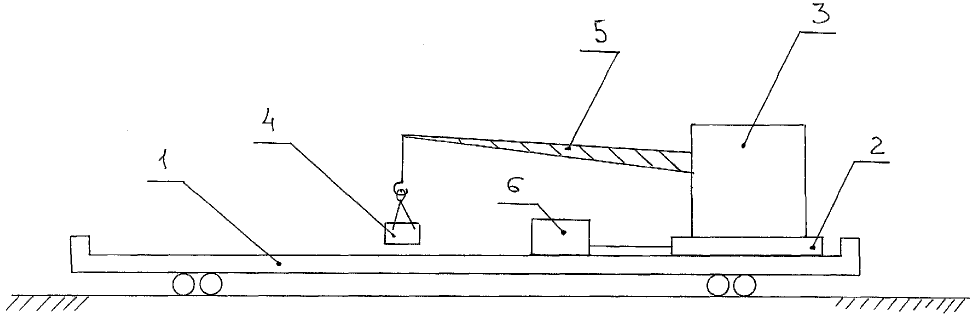
фиг.1 - общая принципиальная сема предлагаемого комплекса;figure 1 - general principle seme of the proposed complex;
фиг.2 - фиг.4 - принципиальная схема вибропогружателя;figure 2 - figure 4 is a schematic diagram of a vibrator;
фиг.5 - фиг.8 - принципиальная схема вибратора;figure 5 - figure 8 is a schematic diagram of a vibrator;
фиг.9 - фиг.10 - принципиальная схема гидравлического зажимного устройства;Fig.9 - Fig.10 is a schematic diagram of a hydraulic clamping device;
фиг.11 - фиг.12 - принципиальная схема гидравлического виброизолятора;11 - Fig.12 is a schematic diagram of a hydraulic vibration isolator;
фиг.13 - принципиальная схема пружинного виброизолятора;Fig is a schematic diagram of a spring vibration isolator;
Предлагаемый комплекс содержит железнодорожную платформу 1, которая в зависимости от условий эксплуатации может представлять The proposed complex contains a railway platform 1, which, depending on operating conditions, may represent
собой как самоходную, так и несамоходную железнодорожную платформу. На железнодорожной платформе 1 предусмотрено опорно-поворотное устройство 2, на котором размещен кран-манипулятор 3 с рабочим органом 4.both self-propelled and non-self-propelled railway platform. On the railway platform 1, a slewing ring 2 is provided, on which a crane 3 with a working body 4 is placed.
Опорно-поворотное устройство 2 предназначено для изменения положения крапа-манипулятора 3 на железнодорожной платформе 1 в течение рабочего процесса, а также перевода крана-манипулятора 3 из транспортного положения в рабочее и наоборот.The rotary support device 2 is designed to change the position of the manipulator 3 on the railway platform 1 during the working process, as well as the transfer of the manipulator 3 from the transport position to the working one and vice versa.
Для специалиста в данной области техники должно быть очевидно, что опорно-поворотное устройство 2 может быть выполнено любым известным способом и иметь любой, подходящий к конкретным условиям эксплуатации, привод, что не является предметом данной заявки.For a person skilled in the art it should be obvious that the slewing ring 2 can be made in any known manner and have any drive suitable for the specific operating conditions, which is not the subject of this application.
Кран-манипулятор 3 предназначен для размещения на его стреле 5 рабочего органа 4 и доставки рабочего органа 4 в зону установки и/или извлечения опор.The crane 3 is designed to be placed on its boom 5 of the working body 4 and the delivery of the working body 4 in the area of installation and / or removal of supports.
Совершенно очевидно, что в зависимости от условий эксплуатации может быть использована любая известная модель крана-манипулятора 3. Тоже самое касается стрелы 5 - она может быть как телескопическая с любым известным приводом, так и не телескопическая.It is obvious that, depending on the operating conditions, any known model of the crane 3 can be used. The same goes for boom 5 - it can be either telescopic with any known drive or non-telescopic.
На крюке крана-манипулятора 3 размещается рабочий орган 4.On the hook of the crane 3 is placed the working body 4.
Для обеспечения энергонезависимости предлагаемого комплекса на железнодорожной платформе 1 может быть предусмотрен автономный источник энергоснабжения 6.To ensure the energy independence of the proposed complex on the railway platform 1, an autonomous source of energy supply 6 can be provided.
На железнодорожной платформе 1 также может быть предусмотрена гидросистема, включающая гидростанцию с гидромоторами, гидробаками и соответствующей арматурой. Наличие гидросистемы призвано обеспечить работоспособность рабочего органа 4, а также, в случае необходимости, опорно-поворотного устройства 2 и/или крана-манипулятора 3 и/или стрелы 5 и/или железнодорожной платформы 1.On the railway platform 1, a hydraulic system may also be provided, including a hydraulic station with hydraulic motors, hydraulic tanks and associated fittings. The presence of the hydraulic system is designed to ensure the operability of the working body 4, as well as, if necessary, the slewing ring device 2 and / or the crane 3 and / or boom 5 and / or the railway platform 1.
Рабочий орган 4 представляет собой вибропогружатель, который может быть использован для погружения и извлечения с использованием железнодорожного крана-манипулятора любых известных свайных фундаментов и опор контактной сети при обустройстве и ремонте контактной сети железных дорог, а также анкеров.The working body 4 is a vibration absorber, which can be used for immersion and extraction using a railway crane, any known pile foundations and supports of the contact network when arranging and repairing the contact network of railways, as well as anchors.
Вибропогружатель представляет собой вибрационную машину направленного действия, работающую совместно с краном-манипулятором 3 и гидравлической станцией.The vibrator is a directional vibration machine that works in conjunction with a crane 3 and a hydraulic station.
Вибропогружатель состоит из вибратора 7, гидравлического зажимного устройства 8, грузовой траверсы 9, виброизолятора 10 (11) и гидрооборудования 12.The vibratory driver consists of a vibrator 7, a hydraulic clamping device 8, a cargo beam 9, a vibration isolator 10 (11) and hydraulic equipment 12.
Основной частью вибропогружателя является вибратор 7, состоящий из корпуса и вмонтированных в него двух валов с установленными на них шестернями и дебалансами. Привод вибратора осуществляется зубчатой передачей от двух гидромоторов.The main part of the vibrator is a vibrator 7, consisting of a housing and two shafts mounted in it with gears and unbalances mounted on them. The vibrator is driven by gear from two hydraulic motors.
Колебания возникают от синхронного вращения двух пар дебалансов, центробежные силы которых уравновешиваются в плоскости, перпендикулярной оси погружаемого элемента, а вдоль оси элемента суммируются и создают знакопеременную возмущающую силу.Oscillations arise from the synchronous rotation of two pairs of unbalances, the centrifugal forces of which are balanced in a plane perpendicular to the axis of the immersed element, and are summed along the axis of the element and create an alternating disturbing force.
Колебания вибратора передаются через жестко закрепленное на нем гидравлическое зажимное устройство 8 погружаемому (извлекаемому) элементу. В зависимости от частоты и направления вращения дебалансных ваплов обеспечиваются различные режимы погружения (извлечения) фундаментов или опор, или анкеров.The vibrations of the vibrator are transmitted through a hydraulic clamping device 8 rigidly fixed on it to the immersed (retrievable) element. Depending on the frequency and direction of rotation of unbalanced vaples, various modes of immersion (extraction) of foundations or supports, or anchors are provided.
Для предотвращения передачи вибрации на кран-манипулятор 3 служат пружинный 10 или гидравлический 11 виброизоляторы, которые навешиваются на крюк крана-манипулятора 3 и соединяются с вибратором 7 с помощью грузовой траверсы 9 и двухветвевых стропов 13.To prevent the transmission of vibration to the crane 3, spring 10 or hydraulic 11 vibration isolators are used, which are hung on the hook of the crane 3 and connected to the vibrator 7 using the load beam 9 and double-branch slings 13.
Вибратор 7 состоит из корпуса, двух валов со сборными дебалансами, установленных в подшипниках и соединенных между собой синхронизирующими зубчатыми колесами, приводных шестерен и гидромоторов.The vibrator 7 consists of a housing, two shafts with prefabricated unbalances installed in bearings and interconnected by synchronizing gears, drive gears and hydraulic motors.
Два вала 15 смонтированы в корпусе 14 на сферических роликовых подшипниках 16, расположены в одной горизонтальной плоскости и связаны друг с другом с помощью зацепляющихся зубчатых колес 17 и 18, что обеспечивает их синхронное вращение в противоположных направлениях.Two shafts 15 are mounted in the housing 14 on spherical roller bearings 16, are located in the same horizontal plane and are connected to each other by means of engaging gears 17 and 18, which ensures their synchronous rotation in opposite directions.
На каждом валу расположены четыре дебаланса, в том числе два основных 19 установлены на шпонках и снабжены цапфами 20, а два дополнительных 21 имеют возможность свободно проворачиваться на валах и своими впадинами зацепляться с цапфами основных дебалансов.Four unbalances are located on each shaft, including two main 19 mounted on the dowels and equipped with 20 pins, and two additional 21 have the ability to freely rotate on the shafts and engage their pits with the pins of the main unbalances.
При прямом вращении валов дебалансные массы складываются, а при реверсировании вращения дебалансы 19 и 21 смещаются друг относительно друга на угол 180°, что позволяет уменьшить статический момент.With a direct rotation of the shafts, unbalanced masses are added, and with a reverse rotation, the unbalances 19 and 21 are displaced relative to each other by an angle of 180 °, which reduces the static moment.
Такое конструктивное исполнение дебаланса позволяет простым реверсированием реализовать вибрационные режимы с большим статическим моментом и низкой частотой и с малым статическим моментом и повышенной частотой.This design of the unbalance allows simple reversal to implement vibration modes with a large static moment and low frequency and with a small static moment and high frequency.
Привод каждого вала осуществляется от своего гидромотора 22, установленного в корпусе 23. Приводные шестерни 24 смонтированы на шариковых подшипниках 25 и зацепляются с гидромоторами с помощью зубчатых муфт 26.Each shaft is driven by its own hydraulic motor 22 installed in the housing 23. The drive gears 24 are mounted on ball bearings 25 and are engaged with the hydraulic motors using gear couplings 26.
Смазка зубчатого зацепления привода валов 15 осуществляется окунанием в масляную ванну колес 17, 18, а подшипников 25 и подшипников 16 со стороны привода - масляным туманом, образующимся Lubrication of the gearing of the drive shaft 15 is carried out by dipping into the oil bath wheels 17, 18, and the bearings 25 and bearings 16 from the drive side - oil fog generated
при вращении колес 17, 18. Уровень масла в корпусе 23 контролируется по масломерному стеклу 27.when the wheels 17, 18 rotate, the oil level in the housing 23 is controlled by the oil sight glass 27.
Подшипники 16 с противоположной стороны смазываются консистентной смазкой.Bearings 16 are greased on the opposite side.
На днище корпуса вибратора приварены четыре тяги для соединения с зажимным устройством, а на боковых листах на цапфах установлены поворотные траверсы 28 для закрепления стропов грузовой траверсы.Four rods are welded on the bottom of the vibrator body for connection with a clamping device, and on the lateral sheets on the trunnions, rotary traverses 28 are installed to secure the slings of the load traverse.
Для защиты гидромоторов от механических повреждений служит рама 29.To protect the hydraulic motors from mechanical damage, the frame 29 is used.
Гидравлическое зажимное устройство 8 предназначено для захвата и удержания фундамента или опоры или анкера в процессе погружения (извлечения).The hydraulic clamping device 8 is designed to capture and hold the foundation or support or anchor during the process of immersion (extraction).
Гидравлическое зажимное устройство 8 состоит из двух зажимных 30 и двух упорных 31 траверс, соединенных хвостовиками тяг корпуса вибратора.The hydraulic clamping device 8 consists of two clamping 30 and two thrust 31 traverses connected by shanks of the rods of the vibrator body.
Зажимная траверса 30 представляет собой сварную конструкцию коробчатого сечения. На верхнем листе траверсы установлен гидроцилиндр штоком вниз. Внутри зажимной траверсы, непосредственно под гидроцилиндром, закреплены направляющая планка 32, в вертикальных пазах типа "ласточкин хвост" которой перемещается клин 33, жестко соединенный со штоком гидроцилиндра. Клин также имеет пазы типа "ласточкин хвост", расположенные наклонно, с которыми взаимодействует клиновая щека 34 с прижимной плитой 35.The clamping beam 30 is a welded box-section structure. On the top sheet of the traverse, the hydraulic cylinder is installed with the stem down. Inside the clamping beam, directly under the hydraulic cylinder, a guide bar 32 is fixed, in the vertical dovetail grooves of which the wedge 33 moves, rigidly connected to the hydraulic cylinder rod. The wedge also has dovetail grooves arranged obliquely with which the wedge cheek 34 interacts with the pressure plate 35.
При втягивании штока гидроцилиндра клин 33 поднимается и перемещает вдоль шпонки клиновую щеку 34 вместе с прижимной плитой 35 в направлении фундамента, которая прижимает фундамент к противоположной упорной траверсе 31.When the hydraulic cylinder rod is retracted, the wedge 33 rises and moves the wedge cheek 34 along the dowel along with the pressure plate 35 in the direction of the foundation, which presses the foundation against the opposite thrust beam 31.
При выдвижении штока клин 33 опускается, перемещает клиновую щеку 34 с прижимной плитой 35 в направлении от фундамента и происходит разжим гидравлического зажимного устройства 8.When the rod is extended, the wedge 33 lowers, moves the wedge cheek 34 with the pressure plate 35 in the direction from the foundation, and the hydraulic clamping device 8 is expanded.
Для защиты крана от вибрации используются два типа виброизолятора - гидравлический 11 при температуре до - 20°С или пружинный 10 при температуре до - 40°С.To protect the crane from vibration, two types of vibration isolators are used - hydraulic 11 at temperatures up to -20 ° C or spring 10 at temperatures up to -40 ° C.
Гидравлический виброизолятор 11 состоит из гидроцилиндра 36 и пневмогидравлического аккумулятора 37, соединенного со штоковой полостью гидроцилиндра 36 переходником 38. Крепится пневмогидравлический аккумулятор 37 к корпусу гидроцилиндра хомутом 39. На проушине гидроцилиндра 36 закреплена скоба 40 для подвешивания гидравлического виброизолятора 11 на крюк крана-манипулятора 3, а на хвостовике штока гидроцилиндра 36 - проушина для соединения с грузовой траверсой 9.The hydraulic vibration isolator 11 consists of a hydraulic cylinder 36 and a pneumatic hydraulic accumulator 37 connected to the rod cavity of the hydraulic cylinder 36 by an adapter 38. The pneumatic hydraulic accumulator 37 is attached to the hydraulic cylinder body with a clamp 39. A bracket 40 is mounted on the eye of the hydraulic cylinder 36 for hanging the hydraulic vibration isolator 11 on the crane hook 3 and on the shank of the rod of the hydraulic cylinder 36 - eye for connection with the cargo beam 9.
Поршневая и штоковая полости гидроцилиндра 36 заполнены амортизаторной жидкостью, например, МГП-12. Залитая в поршневую полость через отверстие 41 жидкость в количестве 0,35...0,4 л (соответствует выдвижению штока на ≈20 мм) создает гидравлическую подушку и предотвращает удары поршня по крышке гидроцилиндра.The piston and rod cavities of the hydraulic cylinder 36 are filled with shock absorber fluid, for example, MGP-12. Liquid poured into the piston cavity through the hole 41 in an amount of 0.35 ... 0.4 l (corresponds to a rod extension of ≈20 mm) creates a hydraulic cushion and prevents piston impacts on the hydraulic cylinder cover.
Газовая полость пневмогидравлического аккумулятора 37 заполнена азотом под давлен нем 3...4 МПа (30...40 кгс/см), который выполняет функции пружины сжатия.The gas cavity of the pneumohydraulic accumulator 37 is filled with nitrogen under a pressure of 3 ... 4 MPa (30 ... 40 kgf / cm), which acts as a compression spring.
Под действием знакопеременной возмущающей силы, возникающей при вращении дебалансов и направленной вдоль оси гидроцилиндра 36, шток с поршнем совершает возвратно-поступательные движения с частотой колебаний вибратора. При этом рабочая жидкость или вытесняется из штоковой полости в пневмогидравлический аккумулятор 37, сжимая газ (движение колеблющейся массы вниз), или под действием давления в газовой полости возвращает шток с поршнем в исходное Under the action of an alternating disturbing force arising from the rotation of the unbalances and directed along the axis of the hydraulic cylinder 36, the rod with the piston reciprocates with the oscillation frequency of the vibrator. In this case, the working fluid is either displaced from the rod cavity into the pneumohydraulic accumulator 37, compressing the gas (the oscillating mass moves downward), or, under the action of pressure in the gas cavity, returns the rod with the piston to the original
положение (движение колеблющейся массы вверх). Таким образом, колебания навешенной на виброизолятор массы поглощаются пневмогидравлическим аккумулятором и не передаются на подъемные канаты крана-манипулятора и его металлоконструкции.position (movement of the oscillating mass up). Thus, the oscillations of the mass hung on the vibration isolator are absorbed by the pneumohydraulic accumulator and are not transmitted to the hoisting ropes of the crane and its metal structure.
В отличие от гидравлического, в пружинном виброизоляторе 10 в качестве гасителя колебаний используется комплект пружин сжатия.Unlike hydraulic, in a spring vibration isolator 10, a set of compression springs is used as a vibration damper.
Пружинный виброизолятор состоит из подвески 42 с грузовой скобой 43 для навешивания на крюк крана-манипулятора 3, тяги 44 с проушиной для соединения с грузовой траверсой 9 и с закрепленным с помощью гайки корпусом 45, направляющей 46 и комплекта пружин 47, установленных на стяжках 48 между фланцами корпуса 45 и направляющей 46. Для предотвращения соударений подвески и тяги служат резиновые проставив 49. Смазываются трущиеся поверхности тяги и направляющей консистентной смазкой.The spring vibration isolator consists of a suspension 42 with a cargo bracket 43 for hanging on a hook of a crane 3, a rod 44 with an eye for connecting to a cargo beam 9 and with a housing 45 fixed with a nut, a guide 46 and a set of springs 47 mounted on couplers 48 between the flanges of the housing 45 and the guide 46. To prevent collisions of the suspension and the traction, the rubber ones are used with rubber 49. The friction surfaces of the traction and the guide grease are lubricated.
В состав гидрооборудования 12 входят гидравлические панели с предохранительными клапанами КП1, КП2 и гидрозамками ЗМ1 и ЗМ2, приводные гидромоторы 22, гидрозамок ЗМЗ и пневмогидроаккумулятор АК1. Все перечисленное оборудование, кроме гидромоторов 22, размещено в пространстве между вибратором 7 и гидравлическим зажимным устройством 8. Подвод и слив рабочей жидкости осуществляется через быстроразъемные соединения МР1...МР5.The hydraulic equipment 12 includes hydraulic panels with safety valves KP1, KP2 and hydraulic locks ЗМ1 and ЗМ2, driving hydraulic motors 22, hydraulic lock ЗМЗ and pneumatic accumulator AK1. All of the listed equipment, except for the hydraulic motors 22, is located in the space between the vibrator 7 and the hydraulic clamping device 8. The supply and discharge of the working fluid is carried out via quick disconnect joints MP1 ... MP5.
Для обеспечения низкочастотного и высокочастотного режимов вибрации гидромоторы 22 соединены по параллельно-последовательной схеме.To ensure low-frequency and high-frequency vibration modes, the hydraulic motors 22 are connected in parallel-serial circuit.
При параллельном соединении рабочая жидкость через разъем МР1 подается одновременно к обоим гидромоторам 22.In a parallel connection, the working fluid through the connector MP1 is supplied simultaneously to both hydraulic motors 22.
Слив рабочей жидкости с первого гидромотора происходит непосредственно через разъем МР2, а со второго гидромотора через The draining of the working fluid from the first hydraulic motor occurs directly through the connector MP2, and from the second hydraulic motor through
гидрозамок ЗМ1, который открывается под действием давления в напорной магистрали, и разъем МР2.hydraulic lock ZM1, which opens under the action of pressure in the pressure line, and connector MP2.
При последовательном соединении поток рабочей жидкости от разъема МР2 направляется только к первому гидромотору, который с удвоенной частотой вращает свой дебалансный вал, через синхронизирующие шестерни второй дебалансный вал и второй гидромотор. При этом второй гидромотор включается в сливную магистраль первого гидромотора через гидрозамок ЗМ2, который открывается под действием давления в напорной магистрали. Второй гидромотор, работая в режиме гидронасоса, перекачивает рабочую жидкость в слив через разъем МР1.When connected in series, the flow of working fluid from the MP2 connector is directed only to the first hydraulic motor, which rotates its unbalanced shaft with double frequency through the synchronizing gears of the second unbalanced shaft and the second hydraulic motor. In this case, the second hydraulic motor is included in the drain line of the first hydraulic motor through the hydraulic lock ZM2, which opens under the action of pressure in the pressure line. The second hydraulic motor, operating in the hydraulic pump mode, pumps the working fluid into the drain through the MP1 connector.
При включении операции "Зажим" рабочая жидкость через разъем МР4 и гидрозамок ЗМЗ подается в штоковые полости гидроцилиндров Ц1, Ц2 гидравлического зажимного устройства и в пневмогидроаккумулятор АК1. Штоки гидроцилиндров, втягиваясь, воздействуют на клиновые механизмы гидравлического зажимного устройства, которые захватывают оголовок фундамента с усилием, ограниченным предохранительным клапаном КПЗ. Одновременно происходит зарядка пневмогидроаккумулятора АК1.When the “Clamp” operation is turned on, the working fluid is supplied through the MP4 connector and ZMZ hydraulic lock to the rod cavities of the hydraulic cylinders C1, C2 of the hydraulic clamping device and to the AK1 pneumatic accumulator. The cylinder rods, retracting, act on the wedge mechanisms of the hydraulic clamping device, which capture the tip of the foundation with a force limited by the pressure relief valve of the bullpen. At the same time, the AK1 pneumatic accumulator is charged.
При выключении операции гидрозамок ЗМЗ закрывается и пневмогидроаккумулятор АК1 поддерживает постоянное усилие зажатия погружаемых (извлекаемых) фундаментов.When the operation is turned off, the ZMZ hydraulic lock closes and the AK1 pneumatic accumulator maintains a constant clamping force of the submerged (extracted) foundations.
Слив рабочей жидкости из поршневых полостей гидроцилиндров осуществляется через разъем МР5.Drain the working fluid from the piston cavities of the hydraulic cylinders through the connector MP5.
При включении операции "Разжим" рабочая жидкость через разъем МР5 подается в поршневые полости гидроцилиндров. Выдвигаясь, штоки воздействуют на клиновые механизмы гидравлического зажимного устройства, которые освобождают оголовок фундамента.When the “Expand” operation is turned on, the working fluid is supplied through the MP5 connector to the piston cavities of the hydraulic cylinders. Advancing, the rods act on the wedge mechanisms of the hydraulic clamping device, which release the tip of the foundation.
Слив рабочей жидкости из штоковых полостей осуществляется через гидрозамок ЗМЗ, который открывается давлением в напорной магистрали, и разъем МР4.The draining of the working fluid from the rod cavities is carried out through the ZMZ hydraulic lock, which opens with pressure in the pressure line, and the MP4 connector.
Предлагаемый комплекс работает следующим образом.The proposed complex works as follows.
Железнодорожная платформа подается к месту проведения работ самостоятельно или с помощью буксировки. На железнодорожной платформе может быть предусмотрено место для складирования предназначенных для установки или извлечения опор (фундамента) или может быть предусмотрена дополнительная грузовая платформа для указанных целей.The railway platform is fed to the place of work on its own or by towing. On the railway platform, a place for storage intended for the installation or extraction of supports (foundations) may be provided, or an additional cargo platform for these purposes may be provided.
Кран-манипулятор с рабочим органом переводятся из транспортного в рабочее положение, для чего должны быть задействованы источник энергоснабжения и гидросистема.The crane with the working body is transferred from the transport to the working position, for which a power supply and hydraulic system must be involved.
Цикл работ по погружению, например, фундаментов (опор) включает:The cycle of immersion work, for example, foundations (supports) includes:
- захват фундамента (опоры) гидравлическим зажимным устройством вибропогружателя;- capture of the foundation (support) with a hydraulic clamping device of a vibro-loader;
- подъем фундамента (опоры) и нацеливание на отметку погружения;- raising the foundation (support) and aiming at the mark of immersion;
- опускание фундамента (опоры) в направляющий котлован до упора в грунт и погружение до заданной отметки с обеспечением его вертикальности с помощью крана-манипулятора;- lowering the foundation (support) into the guide pit until it stops in the ground and immersion to a predetermined elevation with its verticality using a crane;
- освобождение гидравлического зажимного устройства и снятие вибропогружателя с фундамента (опоры).- the release of the hydraulic clamping device and the removal of the vibrator from the foundation (support).
Цикл работ по извлечению фундаментов (опор) включает:The cycle of work on the extraction of foundations (supports) includes:
- нацеливание на извлекаемый фундамент (опору);- targeting the recoverable foundation (support);
- захват фундамента (опоры) гидравлическим зажимным устройством вибропогружателя;- capture of the foundation (support) with a hydraulic clamping device of a vibro-loader;
- извлечение фундамента (опоры);- extraction of the foundation (support);
- укладка фундамента (опоры) на землю.- laying the foundation (support) on the ground.
Погружение фундаментов (опор) производится в режимах высокочастотной и низкочастотной вибрации, при этом режим выбирается в зависимости от скорости погружения.The immersion of foundations (supports) is carried out in high-frequency and low-frequency vibration modes, and the mode is selected depending on the speed of immersion.
Изменение режима погружения обеспечивается реверсированием приводных гидромоторов вибропогружателя с помощью гидрораспределителя насосной станции.Changing the immersion mode is ensured by reversing the drive motors of the vibrator with the help of the control valve of the pumping station.
Погружение в начальный момент и до устойчивого положения фундамента (опоры) должно производиться только в режиме высокочастотной вибрации.Immersion at the initial moment and to a stable position of the foundation (support) should be carried out only in high-frequency vibration mode.
Извлечение фундаментов (опор) должно производиться только в режиме высокочастотной вибрации.Removing foundations (supports) should be done only in high-frequency vibration mode.
Порядок выполнения операций при погружении фундаментов (опор):The order of operations when immersing the foundations (supports):
- уложить краном-манипулятором вибропогружатель на ровную площадку;- lay the vibrator in a flat area with a crane;
- застропить фундамент (опору) по центру массы и завести его краном-манипулятором в гидравлическое зажимное устройство вибропогружателя;- ditch the foundation (support) in the center of mass and turn it into the hydraulic clamping device of the vibro-loader with a crane;
- включить гидрораспределителем насосной станции операцию "Зажим" и зажать фундамент (опору);- turn on the operation “Clamp” with the control valve of the pumping station and clamp the foundation (support);
- поднять вибропогружатель с фундаментом (опорой) и установить последний в подготовленный направляющий котлован до упора в грунт, не ослабляя грузовых стропов;- raise the vibration absorber with the foundation (support) and install the latter in the prepared guide pit until it stops in the ground, without loosening the cargo slings;
- проверить вертикальность фундамента (опоры);- check the verticality of the foundation (support);
- включить гидрораспределителем насосной станции вибропогружатель в высокочастотном режиме и начать медленно опускать вибропогружатель с фундаментом (опорой);- turn on the hydraulic distributor of the pumping station in high frequency mode and start slowly lowering the vibrator with the foundation (support);
- для обеспечения вертикального погружения не допускать ослабления грузовых стропов;- to ensure vertical immersion to prevent the weakening of cargo slings;
- после погружения фундамента (опоры) на 1,2...1,5 м выключить вибропогружатель;- after immersion of the foundation (support) by 1.2 ... 1.5 m, turn off the vibration absorber;
- опустить грузовую траверсу с виброизолятором на 300...400 мм;- lower the cargo beam with vibration isolator by 300 ... 400 mm;
- включить вибропогружатель в низкочастотном режиме и продолжать опускание крюковой обоймы со скоростью погружения фундамента (опоры), не допуская натяжения грузовых стропов;- turn on the vibrator in the low-frequency mode and continue lowering the hook cage with the speed of immersion of the foundation (support), avoiding the tension of cargo slings;
- после погружения фундамента на заданную глубину включить операцию "Разжим" и поднять вибропогружатель с оголовка фундамента (опоры).- after immersing the foundation to a predetermined depth, turn on the “Expand” operation and raise the vibration absorber from the head of the foundation (support).
Порядок выполнения операций при извлечении фундаментов (опор):The order of operations during the extraction of foundations (supports):
- установить краном-манипулятором вибропогружатель на оголовок фундамента (опоры);- install a vibrating driver on the foundation head (supports) with a crane;
- включить гидрораспределителем насосной станции операцию "Зажим" и зажать оголовок фундамента (опоры);- turn on the operation “Clamp” with the control valve of the pumping station and clamp the head of the foundation (support);
- опустить краном грузовую траверсу с виброизолятором на 100...200 мм (ослабить стропы грузовой траверсы);- lower the load beam with a vibration isolator by a crane by 100 ... 200 mm (loosen the load beam slings);
- включить гидрораспределителем насосной станции вибропогружатель в низкочастотном режиме и убедиться, что фундамент (опора) сдвинулся с места, после чего выключить вибропогружатель;- turn on the hydraulic distributor of the pumping station in the low-frequency mode and make sure that the foundation (support) has moved, and then turn off the vibrator;
- включить вибропогружатель в высокочастотном режиме;- turn on the vibrator in high-frequency mode;
- включить механизм подъема крана-манипулятора и натянуть грузовые стропы;- turn on the lifting mechanism of the crane-manipulator and pull the cargo slings;
- извлекать до тех пор, пока в грунте останется часть фундамента (опоры) длиной 0,4...0,5 м для анкера или 1...1,2 м для стакана, после чего выключить вибропогружатель и продолжать подъем;- remove until a part of the foundation (support) remains in the ground with a length of 0.4 ... 0.5 m for the anchor or 1 ... 1.2 m for the cup, then turn off the vibration damper and continue lifting;
- уложить вибропогружатель с извлеченным фундаментом (опорой) на подготовленную площадку;- lay the vibration absorber with the removed foundation (support) on the prepared site;
- включить гидрораспределителем насосной станции операцию "Разжим" и освободить оголовок фундамента (опоры);- turn on the operation "Expand" with the hydraulic distributor of the pumping station and release the head of the foundation (support);
- уложить грузовую траверсу в ложемент;- lay the load beam in the lodgement;
- застропить фундамент (опору) по центру массы и с помощью крана-манипулятора вывести фундамент (опору) из гидравлического зажимного устройства вибропогружателя;- ditch the foundation (support) in the center of mass and, using a crane, lift the foundation (support) out of the hydraulic clamping device of the vibration absorber;
- уложить фундамент (опору) в отведенное место.- lay the foundation (support) in the designated place.
Таким образом, предлагаемые конструкция и компоновка заявляемого комплекса для вибропогружения фундаментов опор контактной сети и анкеров являются простыми и надежными, способствующими повышению производительности, уменьшению энергозатрат и расширению ее эксплуатационных возможностей.Thus, the proposed design and layout of the inventive complex for vibrating the foundations of the supports of the contact network and anchors are simple and reliable, helping to increase productivity, reduce energy consumption and expand its operational capabilities.
Claims (8)
Priority Applications (1)
| Application Number | Priority Date | Filing Date | Title |
|---|---|---|---|
| RU2006118992/22U RU55790U1 (en) | 2006-06-01 | 2006-06-01 | COMPLEX FOR VIBRODOWNING OF FOUNDATIONS OF CONTACT NETWORK SUPPORTS AND ANCHORS |
Applications Claiming Priority (1)
| Application Number | Priority Date | Filing Date | Title |
|---|---|---|---|
| RU2006118992/22U RU55790U1 (en) | 2006-06-01 | 2006-06-01 | COMPLEX FOR VIBRODOWNING OF FOUNDATIONS OF CONTACT NETWORK SUPPORTS AND ANCHORS |
Publications (1)
| Publication Number | Publication Date |
|---|---|
| RU55790U1 true RU55790U1 (en) | 2006-08-27 |
Family
ID=37061712
Family Applications (1)
| Application Number | Title | Priority Date | Filing Date |
|---|---|---|---|
| RU2006118992/22U RU55790U1 (en) | 2006-06-01 | 2006-06-01 | COMPLEX FOR VIBRODOWNING OF FOUNDATIONS OF CONTACT NETWORK SUPPORTS AND ANCHORS |
Country Status (1)
| Country | Link |
|---|---|
| RU (1) | RU55790U1 (en) |
Cited By (1)
| Publication number | Priority date | Publication date | Assignee | Title |
|---|---|---|---|---|
| RU185020U1 (en) * | 2018-02-20 | 2018-11-19 | Общество с ограниченной ответственностью "ВИБРОБУРТЕХНИКА" | RAILWAY MACHINE FOR INSTALLATION AND IMMERSION OF PILES AND PILED FOUNDATIONS OF CONTACT NETWORK SUPPORTS |
-
2006
- 2006-06-01 RU RU2006118992/22U patent/RU55790U1/en not_active IP Right Cessation
Cited By (1)
| Publication number | Priority date | Publication date | Assignee | Title |
|---|---|---|---|---|
| RU185020U1 (en) * | 2018-02-20 | 2018-11-19 | Общество с ограниченной ответственностью "ВИБРОБУРТЕХНИКА" | RAILWAY MACHINE FOR INSTALLATION AND IMMERSION OF PILES AND PILED FOUNDATIONS OF CONTACT NETWORK SUPPORTS |
Similar Documents
| Publication | Publication Date | Title |
|---|---|---|
| CN102425372B (en) | Vibrato-drilling type punching drilling rig | |
| CN104452732A (en) | Self-propelled ramming device for transformer substation foundation | |
| US3280924A (en) | Vibrating machine for plunging piles, thin-walled clindrical casings and plates | |
| CN207332754U (en) | Electric pole is digged pit upright bar integrated apparatus | |
| WO2015014163A1 (en) | Walking-beam pumping unit with new support | |
| CN105256801B (en) | Quick dyke breach pile jetting machine and pile jetting method | |
| CN215367279U (en) | Pile driver | |
| RU55790U1 (en) | COMPLEX FOR VIBRODOWNING OF FOUNDATIONS OF CONTACT NETWORK SUPPORTS AND ANCHORS | |
| RU2139978C1 (en) | Plant for concreting cast-in-place piles | |
| CN220847511U (en) | Be applied to soil stone backfill rolling vibration device in little space | |
| CN108557645B (en) | Steel box girder hoisting limiting buffer device | |
| RU61723U1 (en) | COMPLEX FOR VIBRODOWNING OF FOUNDATIONS OF CONTACT NETWORK SUPPORTS AND ANCHORS | |
| CN218233460U (en) | Engineering construction pile driver equipment | |
| RU73349U1 (en) | DEBALANCE VIBRATOR WITH ADJUSTABLE PARAMETERS | |
| CN104005411B (en) | The construction method and its stake barrel structure of a kind of stake | |
| CN114809142B (en) | Deep foundation pit vertical excavating device | |
| CN214657018U (en) | Vibrating hammer suitable for piling machinery | |
| CN105604060B (en) | Dam breaking opening pile jetting machine and pile jetting method thereof | |
| CN113216138A (en) | Device and method for reinforcing and treating liquefied foundation | |
| CN207685881U (en) | A kind of bracing members support moving device suitable for narrow place | |
| CN105970959A (en) | Pile driver special for building | |
| CN117905062B (en) | High-stability static pile equipment | |
| RU176503U1 (en) | UNIVERSAL EQUIPMENT FOR SCREW DRIVING | |
| CN111425133A (en) | Dewatering well construction device and construction method thereof | |
| RU81211U1 (en) | MOBILE RAILWAY INSTALLATION FOR VIBRO-LOADING OF PILED FOUNDATIONS OF SUPPORTS OF CONTACT NETWORK |
Legal Events
| Date | Code | Title | Description |
|---|---|---|---|
| MM1K | Utility model has become invalid (non-payment of fees) |
Effective date: 20070602 |