RU36734U1 - HYDRAULIC TESTING MACHINE - Google Patents
HYDRAULIC TESTING MACHINEInfo
- Publication number
- RU36734U1 RU36734U1 RU2003135360/20U RU2003135360U RU36734U1 RU 36734 U1 RU36734 U1 RU 36734U1 RU 2003135360/20 U RU2003135360/20 U RU 2003135360/20U RU 2003135360 U RU2003135360 U RU 2003135360U RU 36734 U1 RU36734 U1 RU 36734U1
- Authority
- RU
- Russia
- Prior art keywords
- hydraulic
- testing machine
- lifting
- installation
- power
- Prior art date
Links
- 238000012360 testing method Methods 0.000 title claims description 14
- 238000009434 installation Methods 0.000 claims description 7
- 238000013461 design Methods 0.000 description 4
- 238000007906 compression Methods 0.000 description 2
- 230000007246 mechanism Effects 0.000 description 2
- 230000002159 abnormal effect Effects 0.000 description 1
- 230000006835 compression Effects 0.000 description 1
- 238000004519 manufacturing process Methods 0.000 description 1
- 238000005259 measurement Methods 0.000 description 1
- 239000002184 metal Substances 0.000 description 1
- 238000011160 research Methods 0.000 description 1
- 239000011343 solid material Substances 0.000 description 1
- 238000010998 test method Methods 0.000 description 1
Landscapes
- Investigating Strength Of Materials By Application Of Mechanical Stress (AREA)
Description
Заявляемая полезная модель относится к области исследования прочностных свойств твердых материалов нутем приложения к ним механических усилий, более конкретно, к гидравлическим машинам для испытания образцов металлов на растяжение, сжатие, растяжение-сжатие.The inventive utility model relates to the field of research of the strength properties of solid materials and the application of mechanical forces to them, and more particularly, to hydraulic machines for testing metal samples in tension, compression, tension-compression.
Известны гидравлические испытательные машины, содержащие силовую раму, силовой гидроцилиндр, насосную установку, пневмогидроаккумулятор, приспособления для установки образцов (захваты, серьги, опоры и т.д.), систему управления и измерения.Known hydraulic testing machines containing a power frame, a power hydraulic cylinder, a pump unit, a pneumatic accumulator, devices for installing samples (grips, earrings, supports, etc.), a control and measurement system.
Силовые рамы гидравлических испытательных машин состоят из основания, колонн и траверсы, перемеш;аемой по колоннам при помоши гидроцилиндров подъема. Отличаются силовые рамы способом установки гидроцилиндров подъема.The power frames of hydraulic testing machines consist of a base, columns and a crosshead, mixed along the columns with the help of lifting cylinders. Power frames differ in the way they install lifting cylinders.
Например, на машине универсальной серии 810.16 (MTS, США) корпуса гидроцилиндров подъема жестко закреплены на основании, а штоки - жестко на траверсе.For example, on a machine of the universal 810.16 series (MTS, USA), the bodies of the lifting hydraulic cylinders are rigidly fixed to the base, and the rods are rigidly fixed to the traverse.
Недостатками этой конструкции являются:The disadvantages of this design are:
-сложность технологического процесса изготовления и монтажа основания, колонн и траверсы;- the complexity of the manufacturing process and the installation of the base, columns and yoke;
-возможность отклонения от параллельности осей колонн в общей плоскости или их перекоса, что затрудняет, а иногда и делает невозможным перемещение траверсы.-the possibility of deviation from parallelism of the axes of the columns in the common plane or their skew, which makes it difficult, and sometimes makes it impossible to move the beam.
Наиболее близким по технической сущности к предлагаемой полезной модели является машина PIK-2000.01 (СКБИМ, Россия).The closest in technical essence to the proposed utility model is the machine PIK-2000.01 (SKBIM, Russia).
Основным недостатком аналога является невозможность монтажа штатных приспособлений, а также установки испытуемых образцов и конструкций, вес которых достигает 120 кг и более, без специальных подъемных механизмов (кран-балки, автопогрузчика и др.).The main disadvantage of the analogue is the impossibility of installing standard devices, as well as the installation of test samples and structures, the weight of which reaches 120 kg or more, without special lifting mechanisms (crane-beam, forklift, etc.).
Целью заявляемой полезной модели является устранение этих недостатков и повышение автономности работы машины.The purpose of the claimed utility model is to eliminate these shortcomings and increase the autonomy of the machine.
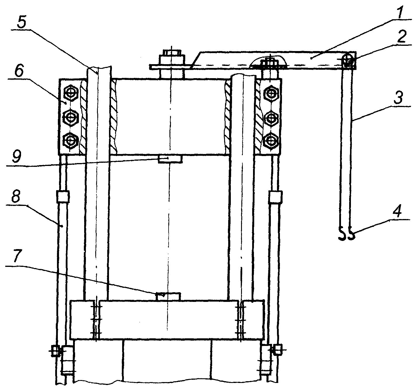
Указанная цель достигается тем, что на подвижной траверсе установлено подъемное устройство (см. иллюстрацию), состояш.ее из балки 1 с блоком 2, через который перекинут трос 3, в концы которого заделаны крюки 4.This goal is achieved by the fact that a lifting device is installed on the movable traverse (see illustration), consisting of a beam 1 with a block 2, through which a cable 3 is thrown, at the ends of which hooks 4 are sealed.
Конструкция предлагаемой полезной модели включает в себя балку 1 с блоком 2, трос 3, крюки 4, колонны 5, траверсу 6, силовой гидроцилиндр 7, гидроцилиндры подъема 8, датчик силы 9, захваты испытуемого образца, установку насосную, усилитель электрогидравлический, блок распределительной и регулируюш;ей гидроаппаратуры, систему управления (на рисунке не показаны).The design of the proposed utility model includes a beam 1 with block 2, cable 3, hooks 4, columns 5, crosshead 6, power hydraulic cylinder 7, hydraulic cylinders 8, force sensor 9, grips of the test sample, pump installation, electro-hydraulic amplifier, distribution block and adjustable; her hydraulic equipment, control system (not shown in the figure).
При необходимости установить на силовую раму машины испытуемый объект или приспособление гидроцилиндры подъема 8 опускают траверсу 6 вместе с установленным на ней подъемным устройством. Крюками 4 зацепляется испытуемый объект. Блок 2 необходим на тот случай, когда испытуемая натурная конструкция имеет точки зацепления на разной высоте.If necessary, install the test object or device on the power frame of the machine, the lifting cylinders 8 lower the yoke 6 together with the lifting device mounted on it. Hooks 4 hooks the test object. Block 2 is necessary in the case when the tested full-scale structure has engagement points at different heights.
Траверса 6 перемещается вверх, поднимая на тросе 3 испытываемый объект (приспособление) на уровень рабочей зоны машины, образуемой колоннами 5, плунжером силового гидроцилиндра 7 и датчиком силы 9.Traverse 6 moves upward, raising the tested object (device) on the cable 3 to the level of the working area of the machine, formed by columns 5, the plunger of the power hydraulic cylinder 7 and the force sensor 9.
Установка объекта (приспособления) и нагружение его .производится согласно методикам испытаний.Installation of the object (device) and its loading. Is carried out according to test methods.
-доступность при ремонте;-availability during repair;
-мобильность (может быть установлен с четырех сторон траверсы);-mobility (can be installed on four sides of the beam);
-замена части ручного труда;-replacement of part of manual labor;
-отсутствие потребности при работе машины в нештатных грузоподъемных механизмах;- lack of need during the operation of the machine in abnormal load-lifting mechanisms;
-автономность при установке - съеме испытуемых объектов.-autonomy during installation - removal of test objects.
Заявляемую полезную модель предполагается использовать в конструкции испытательной универсальной машины ИК 2000.01 и в испытательных машинах подобного типа.The inventive utility model is intended to be used in the design of the testing universal machine IK 2000.01 and in testing machines of this type.
ИСПОЛЬЗОВАННЫЕ ИСТОЧНИКИ:USED SOURCES:
1.Машина универсальная серии 810.16 (каталог фирмы «MTS, США.1. Universal machine 810.16 series (catalog of the company "MTS, USA.
2.Машина универсальная ИК-2000.01 (конструкторская документация СКБИМ, Россия).2. Universal machine IK-2000.01 (design documentation SKBIM, Russia).
Авторы:The authors:
Арутюнян А.Р. . Бессарабенко В.П. Кастанов А.С.Harutyunyan A.R. . Bessarabenko V.P. Kastanov A.S.
Claims (1)
Priority Applications (1)
| Application Number | Priority Date | Filing Date | Title |
|---|---|---|---|
| RU2003135360/20U RU36734U1 (en) | 2003-12-09 | 2003-12-09 | HYDRAULIC TESTING MACHINE |
Applications Claiming Priority (1)
| Application Number | Priority Date | Filing Date | Title |
|---|---|---|---|
| RU2003135360/20U RU36734U1 (en) | 2003-12-09 | 2003-12-09 | HYDRAULIC TESTING MACHINE |
Publications (1)
| Publication Number | Publication Date |
|---|---|
| RU36734U1 true RU36734U1 (en) | 2004-03-20 |
Family
ID=36296969
Family Applications (1)
| Application Number | Title | Priority Date | Filing Date |
|---|---|---|---|
| RU2003135360/20U RU36734U1 (en) | 2003-12-09 | 2003-12-09 | HYDRAULIC TESTING MACHINE |
Country Status (1)
| Country | Link |
|---|---|
| RU (1) | RU36734U1 (en) |
Cited By (2)
| Publication number | Priority date | Publication date | Assignee | Title |
|---|---|---|---|---|
| RU2393453C1 (en) * | 2008-10-16 | 2010-06-27 | Открытое акционерное общество "Специальное конструкторское бюро испытательных машин" (ОАО "СКБИМ") | Power rack for universal testing machine |
| RU2517939C1 (en) * | 2012-10-19 | 2014-06-10 | Федеральное государственное унитарное предприятие "Центральный аэрогидродинамический институт имени профессора Н.Е. Жуковского" (ФГУП "ЦАГИ") | Method of force sensor calibration and device for its implementation |
-
2003
- 2003-12-09 RU RU2003135360/20U patent/RU36734U1/en not_active IP Right Cessation
Cited By (2)
| Publication number | Priority date | Publication date | Assignee | Title |
|---|---|---|---|---|
| RU2393453C1 (en) * | 2008-10-16 | 2010-06-27 | Открытое акционерное общество "Специальное конструкторское бюро испытательных машин" (ОАО "СКБИМ") | Power rack for universal testing machine |
| RU2517939C1 (en) * | 2012-10-19 | 2014-06-10 | Федеральное государственное унитарное предприятие "Центральный аэрогидродинамический институт имени профессора Н.Е. Жуковского" (ФГУП "ЦАГИ") | Method of force sensor calibration and device for its implementation |
Similar Documents
| Publication | Publication Date | Title |
|---|---|---|
| US9588029B2 (en) | Dynamics performance testing system | |
| CN206906142U (en) | Plant equipment crossbeam bend detection means | |
| RU2678935C1 (en) | Servo-hydraulic universal testing machine for mechanical testing of samples of materials in tension, compression, bending and low cycle fatigue in tension-compression | |
| RU135416U1 (en) | AUTOMATED BENCH FOR TESTS OF REINFORCED CONCRETE ELEMENTS ON JOINT ACTION OF BENDING MOMENTS, LONGITUDINAL AND CROSS FORCES UNDER SHORT DYNAMIC LOADING | |
| CN104748959A (en) | Tri-axial multi-dimensional loading mechanics performance test stand | |
| KR101313181B1 (en) | Specimen multiaxial loading test device | |
| CN109443736A (en) | Easy mobile multifunctional is crept into automatically and emulates anchor rod anchored testing stand for a kind of laboratory | |
| CN113340747A (en) | Anchor rod shearing testing device and method | |
| RU36734U1 (en) | HYDRAULIC TESTING MACHINE | |
| CN105509683B (en) | Displacement measuring device for self-balancing pile testing method | |
| CN207051116U (en) | A kind of mine support material mechanical performance comprehensive test device | |
| CN210269445U (en) | Multidimensional loading comprehensive test system | |
| RU2315969C1 (en) | Stand for testing concrete and reinforced concrete members short - time period central and out-of-center dynamic compression | |
| RU152733U1 (en) | STAND FOR TESTING REINFORCED CONCRETE ELEMENTS FOR BENDING WITH STATIC LOADING | |
| RU104718U1 (en) | TESTING MACHINE FOR MECHANICAL TESTS OF BUILDING MATERIALS | |
| CN108414365A (en) | Concrete bursting stress-strain full curve test device under by natural force effect | |
| RU2393453C1 (en) | Power rack for universal testing machine | |
| RU137119U1 (en) | ELECTROMECHANICAL INSTALLATION FOR STATIC AND DYNAMIC TESTS OF CONSTRUCTION STRUCTURES | |
| RU2753981C1 (en) | Servo hydraulic horizontal testing machine for testing cables, ropes, cords and material samples up to ten metres in length | |
| RU210700U1 (en) | Structural Test Bench | |
| RU48225U1 (en) | BENCH FOR TESTING REINFORCED CONCRETE ELEMENTS FOR A SLIDING EXCENTRED SHORT-TERM DYNAMIC STRETCH | |
| CN216144622U (en) | Computer-controlled tension and compression testing machine | |
| RU185718U1 (en) | Test bench for building structures | |
| RU2464545C1 (en) | Device for creation of force fields at strength tests of load handling facilities | |
| RU100255U1 (en) | STAND FOR TEST OF REINFORCED CONCRETE ELEMENTS FOR CROSS BENDING WITH STATIC LOADING |
Legal Events
| Date | Code | Title | Description |
|---|---|---|---|
| MM1K | Utility model has become invalid (non-payment of fees) |
Effective date: 20091210 |