RU32334U1 - Switch - Google Patents
SwitchInfo
- Publication number
- RU32334U1 RU32334U1 RU2003115298/20U RU2003115298U RU32334U1 RU 32334 U1 RU32334 U1 RU 32334U1 RU 2003115298/20 U RU2003115298/20 U RU 2003115298/20U RU 2003115298 U RU2003115298 U RU 2003115298U RU 32334 U1 RU32334 U1 RU 32334U1
- Authority
- RU
- Russia
- Prior art keywords
- contact
- spring
- handle
- housing
- pin
- Prior art date
Links
- 239000004020 conductor Substances 0.000 claims abstract description 4
- 208000035051 Malignant migrating focal seizures of infancy Diseases 0.000 description 1
- 238000013016 damping Methods 0.000 description 1
- 238000004870 electrical engineering Methods 0.000 description 1
- 208000012054 malignant migrating partial seizures of infancy Diseases 0.000 description 1
- 239000002184 metal Substances 0.000 description 1
Landscapes
- Push-Button Switches (AREA)
Abstract
Выключатель, содержащий корпус с крышкой, ручку, выполненную с возможностью поворота в крышке корпуса, первый и второй контакты, контактную пластину и пружину, отличающийся тем, что введены отжимающая пружина, первый и второй контактные элементы, колодка, размещенная внутри корпуса и снабженная в своей верхней части фигурным вырезом, ориентированным в сторону внутренней полой части ручки, штифт и втулка с осью, размещенные в средней части ручки, при этом первый и второй контакты выполнены в виде первой и второй контактных пружин соответственно, которые соединены с соответствующими первым и вторым контактными элементами, снабженными расположенными с внешней стороны корпуса средствами для соединения внешних проводников, пружина размещена в полости внутренней полой части ручки, верхний конец пружины упирается в верхнюю стенку полости ручки, нижний конец пружины находится в контакте с верхним концом штифта, нижний конец которого находится в контакте с фигурным вырезом колодки, контактная пластина закреплена в нижней части колодки с возможностью свободными концами контактировать с первой и второй контактными пружинами, отжимающая пружина своими верхним и нижним концами закреплена в пазе нижней части колодки, выполненном со смещением относительно вертикальной оси колодки, и в пазе нижней части корпуса соответственно.A switch comprising a housing with a cover, a handle rotatable in the housing cover, first and second contacts, a contact plate and a spring, characterized in that a pressing spring, first and second contact elements, a block located inside the housing and provided with the upper part with a curly notch oriented towards the inner hollow part of the handle, a pin and a sleeve with an axis located in the middle part of the handle, while the first and second contacts are made in the form of the first and second contact springs, respectively Connected to the corresponding first and second contact elements equipped with means for connecting external conductors located on the outside of the housing, the spring is placed in the cavity of the inner hollow part of the handle, the upper end of the spring abuts against the upper wall of the handle cavity, the lower end of the spring is in contact with the upper end of the pin, the lower end of which is in contact with the figured notch of the shoe, the contact plate is fixed in the lower part of the shoe with the possibility of free ends of the contact th e first and second contact springs, the urging spring with their upper and lower ends fixed in the groove bottom of the block, performed with an offset relative to the vertical axis of the pad and into the recess of the lower housing part respectively.
Description
ВЫКЛЮЧАТЕЛЬSWITCH
Полезная модель относится к электротехнике и может быть использована при коммутаций электрических цепей постоянного тока при напряжении до тридцати вольт.The utility model relates to electrical engineering and can be used for switching DC electrical circuits at voltages up to thirty volts.
Известно устройство, содержащее металлическое основание, неподвижные и подвижные мостиковые контакты, контактную пружину, закрытую дугогасительную камеру, траверсу, якорь, катушку и магнитопровод электромагнита, амортизирующие пружины, тепловое реле, отключающую пружину, и корткозамкнутый виток на магнитопроводе Электротехнический справочник. В 4-х т., Т. 2, Электротехнические изделия и устройства. Под общей редакцией В.Г. Герасимова и др.. Издательство МЭИ, 1998 г., с. 358, рис. 34.7.A device is known that contains a metal base, fixed and movable bridge contacts, a contact spring, a closed arcing chamber, a traverse, an armature, a coil and an electromagnet magnetic circuit, shock-absorbing springs, a thermal relay that disconnects a spring, and a short-circuited coil on a magnetic circuit. In 4 t., T. 2, Electrical products and devices. Under the general editorship of V.G. Gerasimova et al. Publishing House MPEI, 1998, p. 358, fig. 34.7.
Педостатком устройства является относительно высокая сложность.The disadvantage of the device is a relatively high complexity.
Наиболее близким к предлагаемому является устройство, содержащее ручку и механизм фиксации, включающий корпус, выполненный с возможностью обеспечения вращения ручки, контакты, траверсы (рычаги), контактные пластины, ролики звездочку и пружины Родштейн Л.А. Электрические аппараты: Учебник для техникумов. - 4-е изд., перераб. и доп.-Л.: Энергоатомиздат. Ленингр. отд-ние, 1989. - 304 с., стр. 208, рис. 14Недостатком наиболее близкого технического решения является относительно низкая надежность, вызванная возможной деформацией контактных пластин плоской формы.Closest to the proposed is a device containing a handle and a locking mechanism, including a housing configured to provide rotation of the handle, contacts, traverses (levers), contact plates, sprocket rollers and springs Rodstein L.A. Electrical apparatuses: Textbook for technical schools. - 4th ed., Revised. and Dop.-L .: Energoatomizdat. Leningrad Department, 1989 .-- 304 pp., p. 208, fig. The disadvantage of the closest technical solution is the relatively low reliability caused by the possible deformation of the contact plates of a flat shape.
Требуемый технический результат заключается в повышении надежности.The required technical result is to increase reliability.
Требуемый технический результат достигается тем, что, в устройство, содержащее корпус с крышкой, ручку, выполненную с возможностью поворота в крышке корпуса, первый и второй контакты, контактную пластину и пружину, введены отжимающая пружина, первый и второй контактные элементы, колодка, размещенная внутри корпуса и снабженная в своей верхней части фигурным вырезом, ориентированным в сторону внутренней полой части ручки, штифт и втулка с осью, размещенные в средней части ручки, при этом, первый и второй контакты выполнены в виде первой и второй контактных пружин, соответственно, которые соединены с соответствующими первым и вторым контактными элементами, снабженными расположенными с внешней стороны корпуса средствами для соединения внешних проводников, пружина размещена в полости внутренней полой части ручки, верхний конец пружины упирается в верхнюю стенку полости ручки, нижний конец пружины находится в контакте с верхним концом штифта, нижний конец которого находится в контакте с фигурным вырезом колодки, контактная пластина закреплена в нижней части колодки с возможностью свободными концами контактировать с первой и второй контактными пружинами, отжимающая пружина своими верхним и нижним концами закреплена, в пазе нижней части колодки, выполненном со смещением относительно вертикальной оси колодки, и в пазе нижней части корпуса, соответственно.The required technical result is achieved by the fact that, in the device containing the housing with a cover, a handle made to rotate in the housing cover, the first and second contacts, the contact plate and the spring, a pressing spring, the first and second contact elements, the shoe located inside the casing and provided in its upper part with a figured cutout oriented towards the inner hollow part of the handle, a pin and a sleeve with an axis located in the middle part of the handle, while the first and second contacts are made in the form of the first and A number of contact springs, respectively, which are connected to the corresponding first and second contact elements equipped with means for connecting external conductors located on the outer side of the housing, the spring is placed in the cavity of the inner hollow part of the handle, the upper end of the spring abuts against the upper wall of the cavity of the handle, the lower end of the spring is in contact with the upper end of the pin, the lower end of which is in contact with the figured cut-out of the block, the contact plate is fixed at the bottom of the block with NOSTA free ends in contact with the first and second contact springs, the urging spring with their upper and lower ends secured in the bottom of the recess blocks, performed with an offset relative to the vertical axis of the pad and into the recess of the lower housing part, respectively.
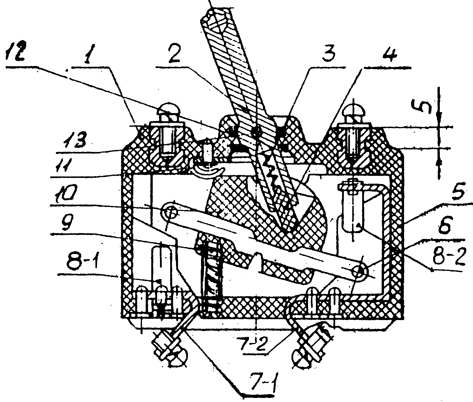
На чертеже представлена конструкция выключателя.The drawing shows the design of the switch.
Выключатель содержит крышку 1, ручку 2, пружину 3, штифт 4, корпус 5, контактную пластина 6, первый 7-1 и второй 7-2 контактные элементы, первую 8-1 и вторую 8-2 контактныеThe switch contains a cover 1, a handle 2, a spring 3, a pin 4, a housing 5, a contact plate 6, the first 7-1 and second 7-2 contact elements, the first 8-1 and second 8-2 contact
пружины, отжимающую пружины 9, колодку 10, пружину 11, втулку 12 с осью 13, при этом, колодка 10 размещена внутри корпуса 5 и снабжена в своей верхней части фигурным вырезом, ориентированным в сторону внутренней полой части ручки 2, втулка 12 с осью 13 размещены в средней части ручки 2, первая 8-1 и вторая 8-2 контактные пружины соединены с соответствующими первым 7-1 и вторым 7-2 контактными элементами, снабженными расположенными с внешней стороны корпуса средствами для соединения внешних проводников, пружина 11 размещена в полости внутренней полой части ручки 2, верхний конец пружины 11 упирается в верхнюю стенку полости ручки 2, нижний конец пружины 11 находится в контакте с верхним концом штифта 4, нижний конец которого находится в контакте с фигурным вырезом колодки 10, контактная пластина 6 закреплена в нижней части колодки 10 с возможностью свободными концами контактировать с первой 8-1 и второй 8-2 контактными пружинами, отжимающая пружина 9 своими верхним и нижним концами закреплена, в пазе нижней части колодки 10, выполненном со смещением относительно вертикальной оси колодки 10, и в пазе нижней части корпуса 5, соответственно.springs, squeezing springs 9, pad 10, spring 11, sleeve 12 with an axis 13, while the pad 10 is placed inside the housing 5 and is provided in its upper part with a curly cut oriented toward the inner hollow part of the handle 2, the sleeve 12 with the axis 13 placed in the middle of the handle 2, the first 8-1 and second 8-2 contact springs are connected to the corresponding first 7-1 and second 7-2 contact elements equipped with means for connecting external conductors located on the outside of the housing, the spring 11 is placed in the cavity inner hollow p 2, the upper end of the spring 11 abuts against the upper wall of the cavity of the handle 2, the lower end of the spring 11 is in contact with the upper end of the pin 4, the lower end of which is in contact with the figured notch of the block 10, the contact plate 6 is fixed at the bottom of the block 10 s the possibility of free ends in contact with the first 8-1 and second 8-2 contact springs, the pressing spring 9 is fixed with its upper and lower ends, in the groove of the lower part of the block 10, made with an offset relative to the vertical axis of the block 10, and in the groove of the lower th part of the housing 5, respectively.
Выключатель работает следующим образом.The switch operates as follows.
При изменении пространственного положения ручки 2 штифт 4 скользит по фигурному вырезу колодки 10 и производит контактное соединение через контактную пластину 6 первой 8-1 и второй 8-2 контактных пластин. Для отключения производится обратное изменение пространственного положения ручки 2, которая удерживается для повышения надежности отключения отжимающей пружиной 9. При этом, благодаря демпфирующим действиям отжимающей пружины 9 и пружины 11 уменьшается возможность деформации контактной пластины 6, выключателя. что повышает надежность When changing the spatial position of the handle 2, the pin 4 slides along the curly cutout of the block 10 and makes a contact connection through the contact plate 6 of the first 8-1 and second 8-2 contact plates. To disconnect, the spatial position of the handle 2 is reversed, which is held to increase the reliability of shutdown by the pressing spring 9. Moreover, due to the damping actions of the pressing spring 9 and spring 11, the possibility of deformation of the contact plate 6 of the switch is reduced. which increases reliability
Автор:Author:
Кычкин В.Ф.Kychkin V.F.
Claims (1)
Priority Applications (1)
| Application Number | Priority Date | Filing Date | Title |
|---|---|---|---|
| RU2003115298/20U RU32334U1 (en) | 2003-05-28 | 2003-05-28 | Switch |
Applications Claiming Priority (1)
| Application Number | Priority Date | Filing Date | Title |
|---|---|---|---|
| RU2003115298/20U RU32334U1 (en) | 2003-05-28 | 2003-05-28 | Switch |
Publications (1)
| Publication Number | Publication Date |
|---|---|
| RU32334U1 true RU32334U1 (en) | 2003-09-10 |
Family
ID=48287014
Family Applications (1)
| Application Number | Title | Priority Date | Filing Date |
|---|---|---|---|
| RU2003115298/20U RU32334U1 (en) | 2003-05-28 | 2003-05-28 | Switch |
Country Status (1)
| Country | Link |
|---|---|
| RU (1) | RU32334U1 (en) |
-
2003
- 2003-05-28 RU RU2003115298/20U patent/RU32334U1/en not_active IP Right Cessation
Similar Documents
| Publication | Publication Date | Title |
|---|---|---|
| BR8206904A (en) | CONTACTOR BEHAVIORING ELECTRY OF CONTROL WITH MOBILE PART AND ASSEMBLY FOR LOAD FEEDING, ITS PROTECTION AND LINE PROTECTION | |
| GB511092A (en) | Improvements in or relating to electrical switching apparatus and sets of contact springs therefor | |
| US3052778A (en) | Electric switch | |
| ES2086794T3 (en) | ELECTRIC SWITCH. | |
| GB480026A (en) | Improvements in and relating to electromagnetic devices | |
| GB1187447A (en) | A Tap Changing Apparatus for an Electric Winding | |
| RU32334U1 (en) | Switch | |
| GB1174756A (en) | Improved Electromagnetic Contactor | |
| US2773948A (en) | Contact arrangement for control relay | |
| US3088058A (en) | Contactor | |
| GB899589A (en) | Electromagnetic contactor | |
| ES419379A1 (en) | AN IMPROVED ELECTRICAL CONTACTOR DEVICE. | |
| GB1352926A (en) | Multi-pole switch mechanism | |
| CN106024528A (en) | Electric self-locking type contactor | |
| GB542668A (en) | Improvements in or relating to electromagnetic relays | |
| RU28795U1 (en) | Switch | |
| GB998482A (en) | Improvements in or relating to cam operated electric switchgear | |
| CN207489764U (en) | A kind of compact electromagnetic relay | |
| ES390705A1 (en) | Oil immersed snap action loadbreak switch | |
| RU28417U1 (en) | Switch | |
| RU17660U1 (en) | SEMI-INSTANT ACTION SWITCH | |
| DE59506477D1 (en) | CONTACT SYSTEM FOR AN ELECTROMAGNETIC SWITCHGEAR WITH QUICK RELEASE | |
| RU1805509C (en) | Heavy-current contact system | |
| SU643699A2 (en) | Electropneumatic valve | |
| SU586508A1 (en) | Contactor |
Legal Events
| Date | Code | Title | Description |
|---|---|---|---|
| MM1K | Utility model has become invalid (non-payment of fees) |
Effective date: 20120529 |